
Macroscopic porous MnO2 aerogels for supercapacitor electrodes†
Kongliang
Xu‡
a,
Xuedong
Zhu‡
b,
Ping
She
a,
Yinxing
Shang
a,
Hang
Sun
*a and
Zhenning
Liu
*a
aKey Laboratory of Bionic Engineering (Ministry of Education), College of Biological and Agricultural Engineering, Jilin University, Changchun, Jilin 130022, P. R. China. E-mail: sunhang@jlu.edu.cn; liu_zhenning@jlu.edu.cn
bCollege of Life Sciences, Jilin University, Changchun, Jilin 130022, P. R. China
First published on 6th June 2016
Abstract
A supercapacitor electrode has been fabricated from macroscopic porous MnO2 aerogels, and has demonstrated an enhanced specific capacitance, a high rate capability and excellent cycling durability. The improvement of supercapacitive performance can be attributed to the macro interconnected channels in the aerogel structure, which can not only facilitate mass transfer and reduce dead volume, but also provide an additional benefit of relieving stress.
Supercapacitors, also known as electrochemical capacitors, have attracted tremendous attention in recent years, owing to their characteristics of high power density and reasonably high energy density.1–3 The energy stored in supercapacitors is either via ion adsorption (as in electrochemical double layer capacitors, EDLCs) or fast surface redox reactions (as in pseudocapacitors).1,4 Compared with EDLCs, pseudocapacitors can achieve much higher energy densities as they often provide multiple oxidation states for efficient redox charge transfer, which satisfy the needs of high energy supercapacitors. Among various electrode materials for pseudocapacitors, manganese dioxide (MnO2) is considered to be one of the most promising materials due to its advantages of low cost, high theoretical capacity, environmental friendliness and natural abundance.2,5,6
Since Lee and Goodenough first demonstrated the use of amorphous MnO2 as a supercapacitive material,7 plenty of studies have been conducted subsequently to understand the charge storage mechanism and further improve the supercapacitive performance.5,8–10 The electrochemical performance of MnO2 has been found to depend on various factors including the morphology, the crystal structure, conductivity, mass loading of the active material, the electrolyte used, etc.5 Recently, a range of zero-dimensional (0D) to three-dimensional (3D) nanostructures,8,11–18 such as 0D nanospheres, 1D nanowires/nanorods/nanobelts/nanotubes, 2D nanosheets/nanoflakes, and 3D nanoflowers/hollow spheres, have been synthesized with MnO2 and their electrochemical properties have been investigated. In particular, 3D MnO2 nanostructures with a porous nature have gained increasing interest owing to the advantages of higher surface area and less dead volume compared to the bulk counterparts.5 However, most reported 3D MnO2 nanostructures are prepared in the form of powders, and the aggregation of these structures during the post-synthesis process (e.g. oven-drying) is often significant,19 resulting in reduced porosity and accessible surface area as well as unsatisfactory supercapacitive performance.
Aerogels are a class of 3D solid materials with low density, wide open pores, high porosity and large inner surface area, which could provide abundant sites for reaction or interfacial transport.20,21 Such 3D macroscopic porous monoliths can be directly fabricated into devices, skipping the conventional drying process of nanostructures and thus avoiding the loss of porosity and accessible surface area.19,22 Recently, MnO2 aerogels have emerged as a new functional material with superior physical and chemical properties. For example, MnO2 aerogels composed of MnO2 nanoflowers and nanowires have been shown to function as a promising catalyst in Li–O2 batteries and adsorbents for cationic dyes or toxic heavy metal ions, respectively.19,23,24 Our previous study has also demonstrated that MnO2 aerogels assembled from MnO2 nanosheets exhibit superior absorbing ability for toxic reducing gas.25 As macro interconnected channels exist in the aerogel structure, it is envisioned that MnO2 aerogels can be used as supercapacitor electrodes with enhanced mass transport. Although there are some cases of supercapacitors fabricated from carbon–MnO2 composite aerogels,26–29 supercapacitor electrodes based on pure MnO2 aerogels haven't been reported yet.
In this communication, we have presented an example of utilizing MnO2 aerogels as supercapacitor electrode materials. The MnO2 aerogels were prepared from ultrathin MnO2 nanosheets via an ice-templating approach. A specific capacitance of up to 139 F g−1 could be obtained from the as-prepared MnO2 aerogels at a current density of 1 A g−1. More importantly, the MnO2 aerogels demonstrate a high rate capability, exhibiting a capacitance retention of 72.7% (101 F g−1) at a current density as high as 20 A g−1. The MnO2 aerogels also show excellent durability, retaining 93.3% of the original capacitance after 5000 charge/discharge cycles at a current density of 10 A g−1. The enhanced supercapacitive performance compared to the MnO2 powder can be attributed to the 3D interconnected ion transport channels in the aerogel structure.
It has been proved that freezing can be used to prepare porous materials with a range of aligned pore architectures, which is mediated by the templating effect of the frozen solvent crystals (typically ice).30 Herein, MnO2 aerogels were fabricated via an ice-templating approach from colloidal MnO2 nanosheets and the two-step preparation is illustrated in Fig. 1a. First, the aqueous MnO2 colloid (the left image of Fig. 1a) was cultivated at −20 °C for 12 hours to form a brown ice-containing chunk (the middle image of Fig. 1a). Subsequently, the ice was removed by sublimation within a freeze dryer, yielding a self-standing MnO2 aerogel without observable volume shrinkage or structure collapse (the right image of Fig. 1a).
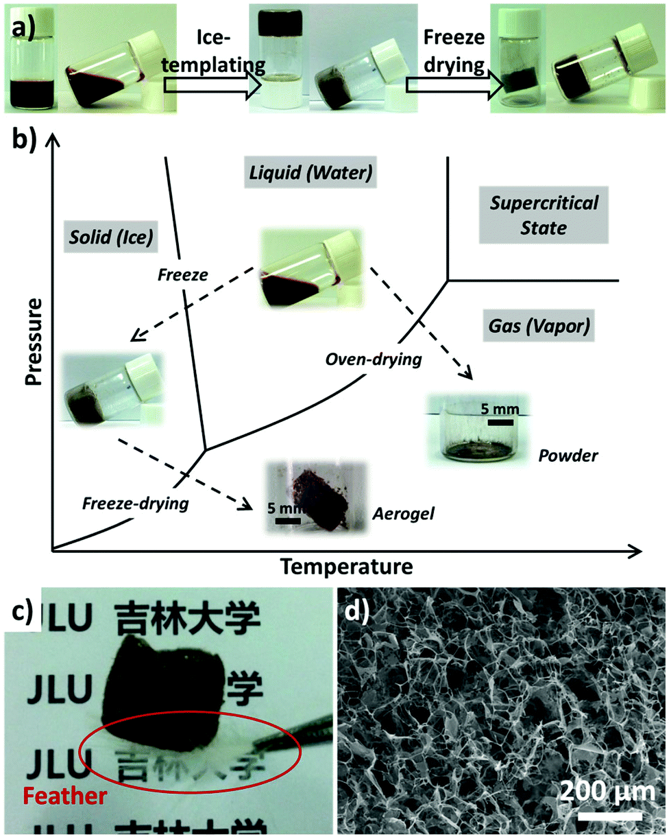 | ||
| Fig. 1 Preparation and characterization of the MnO2 aerogels: (a) photographic illustration of the two-step preparation (i.e. ice-templating and freeze-drying); (b) schematic illustration comparing two approaches: one is to fabricate MnO2 aerogels from colloidal solution via freeze-drying and the other is to obtain MnO2 powder by conventional oven-drying; (c) photograph of the MnO2 aerogel standing on a white feather; (d) SEM image of the as-prepared MnO2 aerogel. | ||
The colloidal MnO2 nanosheets were prepared by a redox reaction between KMnO4 and sodium dodecyl sulfate (SDS) following our previously reported protocol (see the ESI† for details).15,25 The as-prepared colloidal MnO2 displayed two UV-vis absorption peaks centered at 220 and 373 nm, respectively (Fig. S1a†). Characterization using transmission electron microscopy (TEM), scanning electron microscopy (SEM) and atomic force microscopy (AFM) revealed a typical 2D nanosheet morphology with a thickness of about 2.2 nm for the as-prepared MnO2 (Fig. S1b–S1d,† respectively).
The freeze-drying process adopted in our preparation can effectively suppress the collapse of porous structures templated from the ice crystals and thereby achieve 3D aerogels with large open pores. As shown in Fig. 1b, the solvent (i.e. water) is removed via a sublimation process, by passing the liquid–gas phase line and thus minimizing the variation of surface tension before and after drying. Thus a self-standing MnO2 aerogel could be obtained without observable volume shrinkage. In contrast, MnO2 powders without obvious 3D structures (∼99% volume loss, Fig. 1b) would result when the solvent is eliminated by directly crossing the gas–liquid line as in the case of oven-drying.
The resultant aerogel exhibits a foam-like structure of interconnected macropores, which are discernible to the naked eye. It should also be noted that the aerogel possesses a low density of ∼1.0 mg cm−3 and is light enough to stand on a white feather (marked by the red circle, Fig. 1c). SEM was engaged to examine the micro-morphology of the as-prepared aerogel, which revealed a 3D percolating network with open pores ranging from hundreds of nanometers to tens of micrometers (Fig. 1d). It has also been found that the 3D network of the aerogel mainly consists of 2D flakes and 1D rods (Fig. 1d), with typical lateral dimensions of 10–50 μm. The SEM images of higher magnification and TEM images (Fig. S2†) show that the 2D flakes and 1D rods display multiple wrinkles, which are likely caused by stacked nanosheets. Characterization using FT-IR, TGA, XPS, and XRD has also been performed, which indicate that the as-prepared aerogels are of δ-type MnO2 (Fig. S3†).
The as-prepared MnO2 aerogels (A-MnO2) were fabricated into supercapacitor electrodes by mixing with acetylene black and polyvinylidene fluoride (PVDF) at a mass ratio of 70![[thin space (1/6-em)]](https://www.rsc.org/images/entities/char_2009.gif) :20:10. Subsequently, the electrochemical performance of the A-MnO2 electrode was evaluated in an aqueous solution of 1 M Na2SO4 within a three-electrode cell. For comparison, MnO2 powders (P-MnO2) without evident 3D porous structures were also prepared from colloidal MnO2 nanosheets via traditional oven-drying (Fig. 1b and S2†) and the respective electrode was evaluated under the same conditions (see the ESI† for details).
:20:10. Subsequently, the electrochemical performance of the A-MnO2 electrode was evaluated in an aqueous solution of 1 M Na2SO4 within a three-electrode cell. For comparison, MnO2 powders (P-MnO2) without evident 3D porous structures were also prepared from colloidal MnO2 nanosheets via traditional oven-drying (Fig. 1b and S2†) and the respective electrode was evaluated under the same conditions (see the ESI† for details).
Fig. 2a shows the cyclic voltammetry (CV) curves of A-MnO2 recorded between 0 and 1.0 V at various scan rates, all of which exhibit near-rectangular and symmetric shapes, indicating an excellent pseudo-capacitive behavior for A-MnO2 electrodes. Moreover, as the scan rate increases from 5 to 100 mV s−1, the shape of the CV curve displays no obvious distortion and remains rectangular, demonstrating a good rate capability of the electrode. On the contrary, the CV curves of P-MnO2 are seriously distorted into a spindle-like shape with the increment of the scan rate (Fig. 2b). It is noted that the current density of A-MnO2 is much larger than that of P-MnO2 at the same scan rate (for example, 20 mV s−1, as shown in Fig. 2c), indicating a much higher specific capacitance of the A-MnO2 electrode. Corroboratively, the A-MnO2 electrode also shows higher capacitance retention than the P-MnO2 electrode as the scan rate rises (Fig. S4†), suggesting an improved rate capability for A-MnO2 electrodes.
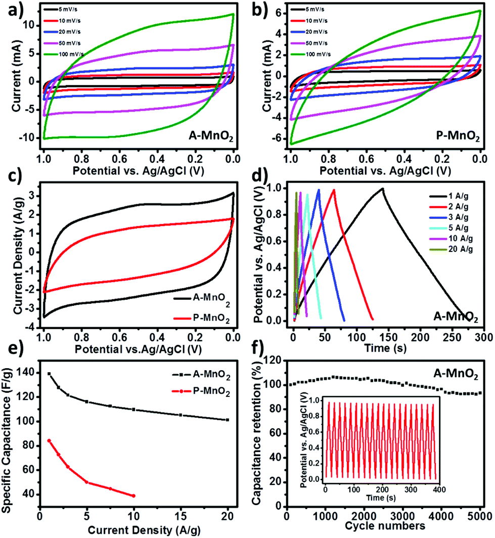 | ||
| Fig. 2 Electrochemical performance of A-MnO2 and P-MnO2 electrodes: (a) CV curves of A-MnO2 at various scan rates; (b) CV curves of P-MnO2 at various scan rates; (c) CV curves of A-MnO2 (black line) and P-MnO2 (red line) at the same scan rate of 20 mV s−1; (d) galvanostatic charge/discharge (GCD) curves of A-MnO2 at different current densities; (e) specific capacitance comparison between A-MnO2 and P-MnO2 at different current densities; (f) cycling performance of A-MnO2 at a current density of 10 A g−1. The inset shows the GCD curves of A-MnO2 electrodes at a current density of 10 A g−1. | ||
The results of galvanostatic charge/discharge (GCD) measurement further corroborate that the aerogels possess enhanced specific capacitance and high rate capability. The device can be steadily operated over a wide range of applied specific currents (from 1 to 20 A g−1) and the GCD curves of A-MnO2 at different current densities are displayed in Fig. 2d. The symmetric near-linear triangular charge–discharge plots show reversible and capacitive behavior of the A-MnO2 electrode. The specific capacitance of A-MnO2 is estimated as 139.1 F g−1 from GCD measurement at the current density of 1 A g−1, whereas only 83.9 F g−1 is observed for P-MnO2 (Fig. S5†) at the same current density. The specific capacitance of our aerogel is higher than the values of most MnO2-based composite aerogels reported in the literature (Table S1†), such as MnO2–graphene aerogels (128 F g−1),27 MnO2 carbonaceous aerogels (123.5 F g−1),28 and MnO2-dispersed carbon aerogels (78 F g−1).29 More importantly, A-MnO2 electrodes are also able to sustain higher specific capacitance at larger current densities. The specific capacitances of A-MnO2 and P-MnO2 at various current densities are plotted in Fig. 2e. Even when the current density increases to 20 A g−1, the specific capacitance of A-MnO2 remains as high as 101.2 F g−1. It should be noted that A-MnO2 retains around 72.7% of the initial capacitance (at 1 A g−1) at 20 times current density (i.e. 20 A g−1), further confirming the good rate capability of MnO2 aerogels. In contrast, the specific capacitance for P-MnO2 is too small to measure with our instrument at a current density higher than 10 A g−1, while the capacitance estimated at the current density of 10 A g−1 declines to 38.8 F g−1, representing a retention of only 46.2% (red line in Fig. 2e).
As long-time cycling stability is an important parameter in assessing the performance of supercapacitors, the A-MnO2 electrode was examined by GCD cycling for 5000 cycles at a current density of 10 A g−1. As shown in Fig. 2f, the relative specific capacitance of A-MnO2 shows a gradual increase in the first 1500 cycles and retains 93.3% of its original capacitance after 5000 cycles, indicating a good cycling durability. The increase in the running-in stage is likely a consequence of the activation of the electrode, similar to the observations made by several other groups.8,12 After 5000 cycles, the charge curves still maintain shapes symmetric to their discharge counterparts (inset of Fig. 2f), suggesting that no significant structural change has been incurred in the A-MnO2 electrode during the charge–discharge cycles. The good cycling performance can be attributed to the high porosity of the aerogels, which can relieve the internal stress incurred during charging and discharging, protecting the electrode from physical damage. Together, the observed high rate capability and excellent durability of A-MnO2 exceed the values of most MnO2 based electrodes (Table S1†),11,15,28,29,31–38 warranting a good promise for practical applications.
In order to understand the charge storage mechanism of MnO2 aerogel supercapacitors, a possible electrochemical reaction is proposed (Fig. 3a) as follows:
| Mn(IV)O2 + xNa+ + yH+ + (x + y)e− ↔ Mn(III)(x+y),Mn(IV)1−(x+y)OONaxHy |
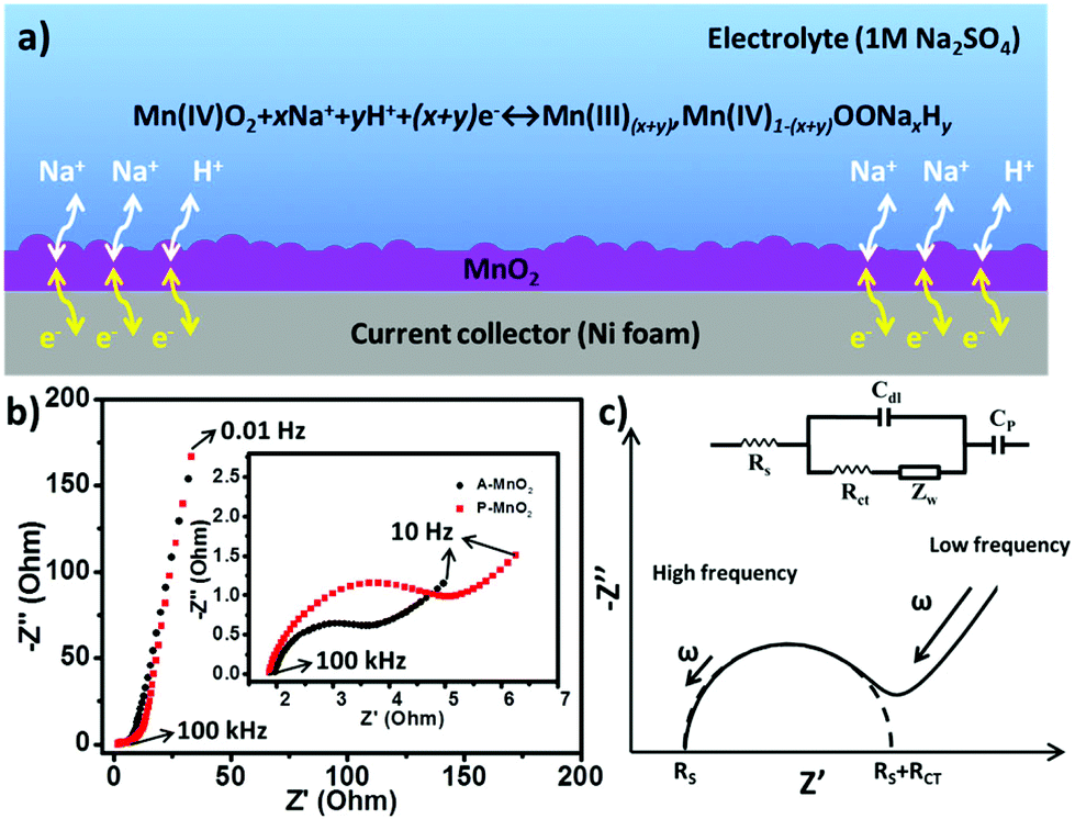 | ||
| Fig. 3 (a) Charge storage mechanism of MnO2 aerogel supercapacitors; (b) Nyquist plots for A-MnO2 (black) and P-MnO2 (red) electrodes; (c) equivalent circuit and the corresponding model for ideal supercapacitors. | ||
The energy storage capacity is likely contributed by the redox reaction of MnO2 together with proton intercalation/extraction and the surface adsorption/desorption of electrolyte cations (Na+).1 The porous structure of aerogels can facilitate the adsorption/desorption of Na+ and the transportation of electrons and protons, allowing better access to electrode materials and improving the utilization of MnO2. As a consequence, an enhanced specific capacitance and a high rate capability can be obtained from the MnO2 aerogels.
To gain further insights, electrochemical impedance spectrum (EIS) measurements were performed for both A-MnO2 and P-MnO2 within a frequency range of 100 kHz to 0.01 Hz. The corresponding Nyquist plots are shown in Fig. 3b, which displayed a semicircle in the high frequency region (inset of Fig. 3b), followed by a linear part in the low frequency region. The Nyquist plots can be fitted by a model based on an equivalent circuit as shown in Fig. 3c.39 In the equivalent circuit (inset of Fig. 3c), an equivalent series resistance (Rs, ESR) connects in series with double-layer capacitance (Cdl) and pseudocapacitance (Cp), and the Cdl connects in parallel with the charge transfer resistance (Rct) and Warburg resistance (Zw). Rs represents the inherent resistance of electrode materials, bulk resistance of the electrolyte and the contact resistance at the active material/current collector interface. Rct (also called Faraday resistance) corresponds to the resistance of the electrochemical reaction on the electrode, whereas Zw correlates with the diffusion of redox species in the electrolyte. The experimental and fitted results (Fig. S6†) show that Rs is constant at a value of around 2.1 Ω for both electrodes. In contrast, Rct of the A-MnO2 electrode (2.1 Ω) is substantially smaller than that of the P-MnO2 electrode (3.9 Ω), suggesting lower ion diffusion resistance and faster charge transport on the A-MnO2 electrode. The steeper Warburg plot of A-MnO2 also indicates faster diffusion of ions toward the electrode.40,41
The observed excellent electrochemical properties (enhanced specific capacitance, high rate capability and excellent cycling durability) of the A-MnO2 electrode can be rationalized by the macroscopic porous structure of the aerogels. First, the porous MnO2 aerogels can provide a large accessible surface area (51 m2 g−1) for the insertion of protons or cations into the electrode (i.e. redox reaction), resulting in enhanced specific capacitance. Second, the large porous channels in the aerogels can facilitate ion transportation and afford better access to active electrode materials, yielding high rate capability. More specifically, such a structure is able to shorten the ion diffusion distance to the electrode and minimize the ion transfer resistance, which can be corroborated by the observed lower Faraday resistance (Rct) and Warburg resistance (Zw) of A-MnO2 as discussed above. Third, the high porosity (as shown in the SEM image of Fig. 1d) can easily relieve the internal stress incurred during charging and discharging, protecting the electrode from physical damage and leading to excellent cycling durability.
In conclusion, the supercapacitor electrode fabricated from MnO2 aerogels has demonstrated an enhanced specific capacitance (139 F g−1 at 1 A g−1), high rate capability (72.7% retention at 20 A g−1) and excellent cycling durability (6.7% loss after 5000 cycles). The improvement of supercapacitive performance can be attributed to the macroscopic 3D interconnected channels in the aerogel structure, which can not only prompt mass transfer and reduce dead volume, but also provide an additional benefit of relieving stress. The high rate capability and cycling stability of our MnO2 aerogels make them a promising electrode material for future energy storage systems.
This work was supported by the National Natural Science Foundation of China (NSFC, 21471067, 51402121, and 51375204), Jilin Provincial Science & Technology Department (20140520163JH and 20140101056JC), and Scientific Research Foundation for the Returned Overseas Chinese Scholars, State Education Ministry.
Notes and references
- P. Simon and Y. Gogotsi, Nat. Mater., 2008, 7, 845–854 CrossRef CAS PubMed.
- W. F. Wei, X. W. Cui, W. X. Chen and D. G. Ivey, Chem. Soc. Rev., 2011, 40, 1697–1721 RSC.
- H. Wang, B. W. Zhu, W. C. Jiang, Y. Yang, W. R. Leow, H. Wang and X. D. Chen, Adv. Mater., 2014, 26, 3638–3643 CrossRef CAS PubMed.
- G. P. Wang, L. Zhang and J. J. Zhang, Chem. Soc. Rev., 2012, 41, 797–828 RSC.
- M. Huang, F. Li, F. Dong, Y. X. Zhang and L. L. Zhang, J. Mater. Chem. A, 2015, 3, 21380–21423 CAS.
- V. Augustyn, P. Simon and B. Dunn, Energy Environ. Sci., 2014, 7, 1597–1614 CAS.
- H. Y. Lee and J. B. Goodenough, J. Solid State Chem., 1999, 144, 220–223 CrossRef CAS.
- W. Chen, R. B. Rakhi, Q. Wang, M. N. Hedhili and H. N. Alshareef, Adv. Funct. Mater., 2014, 24, 3130–3143 CrossRef CAS.
- S. Chen, J. W. Zhu, X. D. Wu, Q. F. Han and X. Wang, ACS Nano, 2010, 4, 2822–2830 CrossRef CAS PubMed.
- M. Toupin, T. Brousse and D. Belanger, Chem. Mater., 2004, 16, 3184–3190 CrossRef CAS.
- H. Jiang, T. Zhao, J. Ma, C. Y. Yan and C. Z. Li, Chem. Commun., 2011, 47, 1264–1266 RSC.
- X. H. Lu, D. Z. Zheng, T. Zhai, Z. Q. Liu, Y. Y. Huang, S. L. Xie and Y. X. Tong, Energy Environ. Sci., 2011, 4, 2915–2921 CAS.
- M. Huang, Y. X. Zhang, F. Li, L. L. Zhang, R. S. Ruoff, Z. Y. Wen and Q. Liu, Sci. Rep., 2014, 4, 3878 Search PubMed.
- L. Wei, C. Q. Li, H. B. Chu and Y. Li, Dalton Trans., 2011, 40, 2332–2337 RSC.
- Z. Liu, K. Xu, H. Sun and S. Yin, Small, 2015, 11, 2182–2191 CrossRef CAS PubMed.
- H. Sun, K. Xu, M. Huang, Y. Shang, P. She, S. Yin and Z. Liu, Appl. Surf. Sci., 2015, 357, 69–73 CrossRef CAS.
- M. Huang, X. L. Zhao, F. Li, L. L. Zhang and Y. X. Zhang, J. Power Sources, 2015, 277, 36–43 CrossRef CAS.
- K. Lei, L. Cong, X. Fu, F. Cheng and J. Chen, Inorg. Chem. Front., 2016 10.1039/c6qi00056h.
- S. Chen, G. X. Liu, H. Yadegari, H. H. Wang and S. Z. Qiao, J. Mater. Chem. A, 2015, 3, 2559–2563 CAS.
- A. C. Pierre and G. M. Pajonk, Chem. Rev., 2002, 102, 4243–4265 CrossRef CAS PubMed.
- H. D. Gesser and P. C. Goswami, Chem. Rev., 1989, 89, 765–788 CrossRef CAS.
- S. Chen, J. J. Duan, W. Han and S. Z. Qiao, Chem. Commun., 2014, 50, 207–209 RSC.
- Y. Long, J. F. Hui, P. P. Wang, S. Hu, B. Xu, G. L. Xiang, J. Zhuang, X. Q. Lu and X. Wang, Chem. Commun., 2012, 48, 5925–5927 RSC.
- S. M. Jung, H. Y. Jung, W. J. Fang, M. S. Dresselhaus and J. Kong, Nano Lett., 2014, 14, 1810–1817 CrossRef CAS PubMed.
- Z. Liu, K. Xu, P. She, S. Yin, X. Zhu and H. Sun, Chem. Sci., 2016, 7, 1926–1932 RSC.
- X. Yang, K. Y. Shi, I. Zhitomirsky and E. D. Cranston, Adv. Mater., 2015, 27, 6104–6109 CrossRef CAS PubMed.
- C. C. Ji, M. W. Xu, S. J. Bao, Z. J. Lu, C. J. Cai, H. Chai, R. Y. Wang, F. Yang and H. Wei, New J. Chem., 2013, 37, 4199–4205 RSC.
- Y. M. Ren, Q. Xu, J. M. Zhang, H. X. Yang, B. Wang, D. Y. Yang, J. H. Hu and Z. M. Liu, ACS Appl. Mater. Interfaces, 2014, 6, 9689–9697 CAS.
- G. Lv, D. C. Wu and R. W. Fu, J. Non-Cryst. Solids, 2009, 355, 2461–2465 CrossRef CAS.
- H. Zhang and A. I. Cooper, Adv. Mater., 2007, 19, 1529–1533 CrossRef CAS.
- K. Kuratani, K. Tatsumi and N. Kuriyama, Cryst. Growth Des., 2007, 7, 1375–1377 CAS.
- S. L. Chou, J. Z. Wang, S. Y. Chew, H. K. Liu and S. X. Dou, Electrochem. Commun., 2008, 10, 1724–1727 CrossRef CAS.
- J. P. Ni, W. C. Lu, L. M. Zhang, B. H. Yue, X. F. Shang and Y. Lv, J. Phys. Chem. C, 2009, 113, 54–60 CAS.
- P. Yu, X. Zhang, D. L. Wang, L. Wang and Y. W. Ma, Cryst. Growth Des., 2009, 9, 528–533 CAS.
- G. X. Zhao, J. X. Li, L. Jiang, H. L. Dong, X. K. Wang and W. P. Hu, Chem. Sci., 2012, 3, 433–437 RSC.
- S. Chen, J. W. Zhu and X. Wang, ACS Nano, 2010, 4, 6212–6218 CrossRef CAS PubMed.
- X. Y. Xie, C. Zhang, M. B. Wu, Y. Tao, W. Lv and Q. H. Yang, Chem. Commun., 2013, 49, 11092–11094 RSC.
- G. R. Li, Z. P. Feng, Y. N. Ou, D. C. Wu, R. W. Fu and Y. X. Tong, Langmuir, 2010, 26, 2209–2213 CrossRef CAS PubMed.
- Y. Huang, Y. Y. Li, Z. Q. Hu, G. M. Wei, J. L. Guo and J. P. Liu, J. Mater. Chem. A, 2013, 1, 9809–9813 CAS.
- D. Ghosh, S. Giri and C. K. Das, Nanoscale, 2013, 5, 10428–10437 RSC.
- B. Subramanya and D. K. Bhat, New J. Chem., 2015, 39, 420–430 RSC.
Footnotes |
| † Electronic supplementary information (ESI) available: Experimental details and supplementary figures. See DOI: 10.1039/c6qi00110f |
| ‡ These authors contributed equally to this work. |
| This journal is © the Partner Organisations 2016 |