
Hollow mesoporous SiO2 sphere nanoarchitectures with encapsulated silver nanoparticles for catalytic reduction of 4-nitrophenol†
Weiqiang
Li‡
a,
Xiao
Ge‡
ab,
Hao
Zhang
a,
Qianqian
Ding
a,
Hualin
Ding
a,
Yunxia
Zhang
*a,
Guozhong
Wang
a,
Haimin
Zhang
a and
Huijun
Zhao
*ac
aKey Laboratory of Materials Physics, Centre for Environmental and Energy Nanomaterials, Anhui Key Laboratory of Nanomaterials and Nanotechnology, Institute of Solid State Physics, Chinese Academy of Sciences, Hefei 230031, China. E-mail: yxzhang@issp.ac.cn
bUniversity of Science and Technology of China, Hefei 230026, P. R. China
cCentre for Clean Environment and Energy, Gold Coast Campus, Griffith University, Queensland 4222, Australia. E-mail: h.zhao@griffith.edu.au
First published on 5th February 2016
Abstract
Ideally, a superior catalyst should possess high speed, selectivity and stability. However, it is difficult to holistically achieve high speed, selectivity and stability catalysis with modest configured catalyst structures. This work reports a new pre-shell/post-core approach combined with a laser ablation treatment strategy to fabricate a sophisticated catalyst architecture configured with a hollow mesoporous SiO2 (hm-SiO2) sphere shell and multiple encapsulated Ag nanoparticle (NP) yolks (Ag@hm-SiO2). Each Ag@hm-SiO2 nanosphere encapsulates 5–10 Ag NP yolks with an average size of 20 nm, in which the content of silver is about 3.6 wt% based on the inductively coupled plasma measurement. To further enhance the catalytic activity, a laser ablation treatment strategy is innovatively utilized to reduce the sizes of the encapsulated Ag NP yolks and increase their numbers. The catalytic reduction of 4-nitrophenol (4-NP) is used to evaluate the catalytic performance of the fabricated Ag@hm-SiO2 catalyst architecture before and after laser ablation treatment. The laser ablation treated Ag@hm-SiO2 nanospheres demonstrate a three-fold increased catalytic activity towards 4-NP reduction with excellent stability. Such superior catalytic performance could be attributed to the unique structural features of the Ag@hm-SiO2 architecture, in which the mesopore shell provides not only readily accessible pathways for fast transport of reactants to the encapsulated Ag NPs but also an effective protective shield for the encapsulated Ag NPs.
1. Introduction
Noble metal nanoparticles (NPs) have been widely used as catalysts for hydrogenation, oxidation/reduction and other reactions.1 However, owing to the high surface energy, pristine noble metal NP-based catalysts are usually unstable and susceptible to severe aggregation during catalytic processes, leading to rapid degradation of the catalytic activity.2 Moreover, due to their small sizes, the recovery of NP-based catalysts is difficult, which hinders their wide practical applications in heterogeneous catalysis. An extensive effort has therefore been devoted to addressing these critical issues with attempts to enhance the stability and facilitate the catalyst recovery.3 A most straightforward and widely adopted approach is to anchor noble metal NPs onto appropriate solid supports.4 Although such approaches make it easier to recover NPs, the immobilised NPs on solid supports lead to a loss of mobility and the reduction of active sites. Also, this type of approach is incapable of preventing the aggregation among the adjacent particles. Recently, a new approach based on the encapsulation of NP catalysts inside porous inorganic shell structures has been proposed to address the above issues.5 Such a core/porous shell catalyst configuration is advantageous compared with the direct anchoring of NPs on solid supports. On the one hand, the encapsulated NP is prevented from aggregation, while the porous shell structure allows for free access of reactants to the catalytically active NPs. On the other hand, the encapsulated NPs in different shell structures act independently with high mobility, benefiting the catalytic activity and enabling facile removal from the reaction mixture by means of filtration or centrifugation. Additionally, the selectivity, an important performance parameter of catalysts, can be improved with a suitable porous shell structure. Nevertheless, this type of core/shell catalyst configuration has unavoidable drawbacks: (i) the tight married core and shell reduce the accessible active surface areas of the encapsulated NP; (ii) each capsule could only accommodate a single NP, which is unfavourable for further catalytic performance enhancement; (iii) the sizes of the encapsulated NP are relatively large with difficulties to be reduced further.In this regard, a yolk/shell (Y/S) configuration can be useful as its interstitial hollow space allows the full utilisation of the active surface of the encapsulated NP. Also, the hollow space of the Y/S structure confines a unique reaction environment favourable for catalytic reactions.6 Moreover, the Y/S configuration has an additional advantage of superior kinetics, resulting from the efficient mass transport provided by the freely movable catalytically active yolk NPs. For example, a recently reported Y/S structured catalyst with Fe0 NPs encapsulated by a mesoporous SiO2 shell demonstrated a high conversion efficiency, excellent selectivity and good stability for Fenton-reactions.7 Similar catalytic performance enhancement effects were also obtained from Y/S configured catalysts made of Pt and Au NPs encapsulated in porous carbon and ZrO2 shells for a range of important hydrogenation reactions and CO oxidation, respectively.8 Compared with the core/shell configuration, the encapsulation of multiple NPs into one capsule for catalytic performance enhancement was the most distinctive advantage of the Y/S configuration.9 Liu and co-workers have recently reported a Y/S structured catalyst with multiple Pd NPs encapsulated in a hybrid periodic mesoporous organosilica shell, which demonstrated a markedly improved conversion efficiency, selectivity and stability for alcohol oxidation reactions.9a Xiao and co-workers successfully synthesized a high performance Y/S structured bimetallic Au nanorod-Pt@hm-SiO2 catalyst by incorporating noble metal nanostructures inside hollow mesoporous silica microspheres for o-phenylenediamine oxidation with H2O2.9b Chen et al. designed a Pd@meso-SiO2 nanoarchitecture that showed a superior activity toward Suzuki coupling reactions, achieving a 99.5% yield within 3 min.9c To date, the majority of methods used to fabricate the Y/S catalyst with single/multiple encapsulated NPs were through a template-assisted process,10 a template-free method,11 Kirkendall or Ostwald ripening effects12 and a spray pyrolysis method.13 Although these representative efforts were based on different mechanisms and physical/chemical processes, they could be simply divided into two so-called “pre-core/post-shell” and “pre-shell/post-core” routes. For the former one, Y/S configurations were produced by coating one layer or two layers of different shells on the preformed core materials, followed by selectively etching the inner layer of the two shells or part of the core (shell) using suitable chemical or calcination treatment.3a,14 The latter one was based on a “reverse” process, in which the metal core was introduced into the cavity of the preformed hollow mesoporous shells via various processes.7,15 For example, the Au NP yolk was introduced into a silica nanorattle with a mesoporous shell in the presence of a reductive reagent of N-[3-(trimethoxysilyl)propyl]ethylenediamine.15c Cheng and co-workers designed an easy photo-reductive method to prepare Ag NP yolks in polypyrrole–chitosan hollow nanospheres.15d However, the majority of the reported approaches are only propitious for one-in-one encapsulation, producing the Y/S nanostructures with a single yolk. It can be envisaged that the performance, functionality and applicability of the Y/S configured catalyst architectures will be undoubtedly improved by developing a facile and effective synthetic approach capable of encapsulating multi-nano-yolks within desirable shell structures. Such emerging porous shell/multi-nano-yolk catalyst architectures can be an effective means to holistically achieve high speed, selectivity and stability catalysis.
Herein, we report a new pre-shell/post-core approach combined with a laser ablation treatment strategy for facile fabrication of a multi-nano-yolk/porous shell catalyst nanoarchitecture consisting of multiple NP Ag yolks encapsulated in a hollow spherical mesoporous nano-sized shell (Ag@hm-SiO2). A laser ablation treatment strategy is innovatively employed to dramatically reduce the sizes of the encapsulated Ag NP yolks and increase their numbers without damaging the hm-SiO2 shell. The reduction of 4-NP in the presence of NaBH4 is used as a model reaction to evaluate the catalytic performance of the fabricated Ag@hm-SiO2 nanoarchitecture.
2. Experimental section
2.1 Chemicals
Tetraethyl orthosilicate (TEOS, 98%), ammonia solution (25–28%), methanol, ethanol, sodium carbonate, and hydroquinone were obtained from Sinopharm Chemical Reagent Co. Ltd. Silver nitrate, sodium iodide and octadecyltrimethoxysilane (C18TMS, GC, ≥90%) were purchased from Shanghai Reagent Factory, Tianjin Guangfu Fine Chemical Research Institute and Aladdin reagent (Shanghai) Co. Ltd., respectively. All reagents were used as received without further purification. All solutions were prepared using deionized water produced by a Millipore system.2.2 Synthesis of hm-SiO2 nanospheres
The hm-SiO2 nanospheres were synthesized according to a reported method with some modifications.17 In a typical procedure, 6.0 mL of TEOS was added to a solution containing 10.0 mL of deionized water, 71.4 mL of ethanol and 3.14 mL of ammonia solution under constant stirring for 4 h in a 30 °C water bath to obtain a solid SiO2 (s-SiO2) nanosphere suspension. The as-obtained s-SiO2 nanosphere suspension was diluted with a mixture solution of 71.4 mL of ethanol and 5.0 mL of deionized water. A pre-mixed solution consisting of 4.0 mL of TEOS, 1.6 mL of C18TMS and 10.0 mL of ethanol was added into the diluted s-SiO2 nanosphere suspension at a speed of 8.0 mL h−1 under constant stirring for 4 h in a 30 °C water bath. The obtained product was centrifuged with 1000 rpm for 5 min. The separated product was then dispersed in a 100 mL aqueous solution containing 0.4 M Na2CO3 in a 50 °C water bath and rigorously stirred for 10 h to remove the s-SiO2. The resulting hm-SiO2 nanospheres were separated by centrifugation and alternatively washed with deionized water and ethanol, respectively, for several times. Afterwards, the hm-SiO2 nanospheres were dried at 60 °C and calcined at 550 °C for 6 h to remove the pore-making agent (C18TMS).2.3 Synthesis of Ag@hm-SiO2 nanospheres
The Ag@hm-SiO2 nanospheres were obtained through a sequential impregnation–transformation–reduction process. Typically, 20 mg of the as-synthesized hm-SiO2 nanospheres was dispersed in 30.0 ml of methanol with strong ultrasonic treatment for 3 min, followed by adding 500 μL of 1.0 M silver nitrate under vigorous stirring for 30 min at room temperature. 5.0 mL of NaI methanol solution (0.108 M) was added into the above reaction solution by using a syringe pump at a speed of 5.0 mL h−1 with moderate magnetic stirring for 2 h, followed by adding 5.0 mL of methanol solution containing 0.099 M hydroquinone at a speed of 2.5 mL h−1 with moderate magnetic stirring. Once the formed silver aggregates outside the hm-SiO2 nanospheres were settled at the bottom of the container, the top suspension was centrifuged at 12![[thin space (1/6-em)]](https://www.rsc.org/images/entities/char_2009.gif) 000 rpm for 5 min to obtain the Ag@hm-SiO2 nanospheres. The obtained product was washed with deionized water and ethanol for several times and dried in a vacuum oven at 60 °C overnight.
000 rpm for 5 min to obtain the Ag@hm-SiO2 nanospheres. The obtained product was washed with deionized water and ethanol for several times and dried in a vacuum oven at 60 °C overnight.
2.4 Laser ablation treatment
2.5 mg of the as-synthesized Ag@hm-SiO2 nanospheres were dispersed into 10 mL of methanol in a glass vessel and subjected to Nd:YAG laser beam ablation for 10 min, in which the glass vessel was rotated at a constant rate of 50 rpm. The laser beam was an unfocused 532 nm beam having a 10 mm diameter irradiation window, operated with the pulse duration of 7 ns, repetition frequency of 20 Hz and energy density of 0.8 mJ cm−2. The laser ablation treated Ag@hm-SiO2 nanospheres were then collected by centrifugation, washed with ethanol for several times and dried in a vacuum oven at 60 °C overnight.2.5 Catalytic performance evaluation
The catalytic reduction of 4-NP was monitored by UV–vis spectroscopy. In a typical process, the catalyst (2.0 mg of Ag@hm-SiO2 nanospheres) was added into 200 mL of Millipore water to form a homogeneous suspension via ultrasonication, followed by adding 0.50 mL of 0.80 M freshly prepared NaBH4 aqueous solution. 0.20 mL of 0.016 M 4-NP solution was then added into the reaction solution. The first UV–vis spectrum of the reaction solution within a wavelength range of 200–900 nm was recorded immediately after the 4-NP was added and additional UV–vis spectra were recorded consecutively every 2 minutes. The extent of 4-NP catalytic reduction was quantified using the absorbance peak intensity at 400 nm. For reuse/stability experiments, the catalyst was recovered by centrifugation after a catalytic experimental cycle, and thoroughly washed with water and ethanol before reuse.2.6 Characterization
The morphology and size of all as-synthesized samples were characterized by transmission electron microscopy (TEM, JEM-2010, 200 kV) and field-emission scanning electron microscopy (FESEM, Sirion 200, 10 kV). The compositions of the resulting products were tested by energy-dispersive X-ray spectroscopy (EDX) attached to TEM. The nitrogen adsorption–desorption isotherms were measured using an automated gas sorption analyzer (Autosorb-iQ-Cx). The UV–vis absorbance spectra were recorded on a Shimadzu UV 3600 spectrophotometer. The contents of silver NPs in the hm-SiO2 spheres were determined by using an Inductively Coupled Plasma Optical Emission Spectrometer (ICP-OES, ThermoiCAP 6300). The particle size distribution was analyzed by using Image J software. The zeta potential of the hm-SiO2 spheres was measured by using a Zetasizer 3000SHa.3. Results and discussion
3.1. In situ encapsulation of multiple nanoparticulate Ag yolks into a hm-SiO2 shell
The hm-SiO2 nanospheres are obtained using a reported selective etching method.16Fig. 1a shows a typical FESEM image of the resulting hm-SiO2 nanospheres, revealing high uniformities in both size and morphology with a corrugated surface. The hollow structure is clearly evidenced by the image of a broken nanosphere (the inset in Fig. 1a). The TEM image in Fig. 1b confirms that the as-synthesized hm-SiO2 spheres possess a well-defined spherical shell and cavity structures, having a uniform diameter and shell thickness of 230 and 23 nm, respectively. It is also revealed that the shell is constructed by irregularly interconnected SiO2 NPs, resulting in a uniformly distributed porous shell structure.17 The nitrogen absorption–desorption analyses (Fig. S1, ESI†) reveal a surface area of 94 m2 g−1 and a pore volume of 0.59 cm3 g−1, which is lower than that of the reported hollow SiO2 capsules.7,8b,9c,16b,17 As we know, the –Si–O–Si– bond is not stable under alkaline conditions, partial –Si–O–Si– bonds will be broken to form small pores, and the formed small pores can further fuse with each other to generate larger pores. In the meantime, the alkaline etching of silica is a reversible reaction.16a It is possible that the regrowth process occurs by the condensation of the partial broken Si–O bonds on the pore surfaces, resulting in the formation of the partial nearly nonporous hollow silica nanocapsules, as evidenced by Fig. S2 (see the ESI†), which explains why the obtained nanoparticles had a lower surface area. The pore-size distribution determined from the Barrett–Joyner–Halenda (BJH) method is found to be 3.4–16.9 nm with an average pore-size of 5.3 nm, confirming a mesoporous structured shell. Such mesopores are favourable for rapid mass transport. The obtained hm-SiO2 nanospheres can be used as capsules to accommodate Ag NP yolks. In this work, a new impregnation approach is employed to in situ encapsulate multiple Ag NP yolks into the hm-SiO2 nanospheres.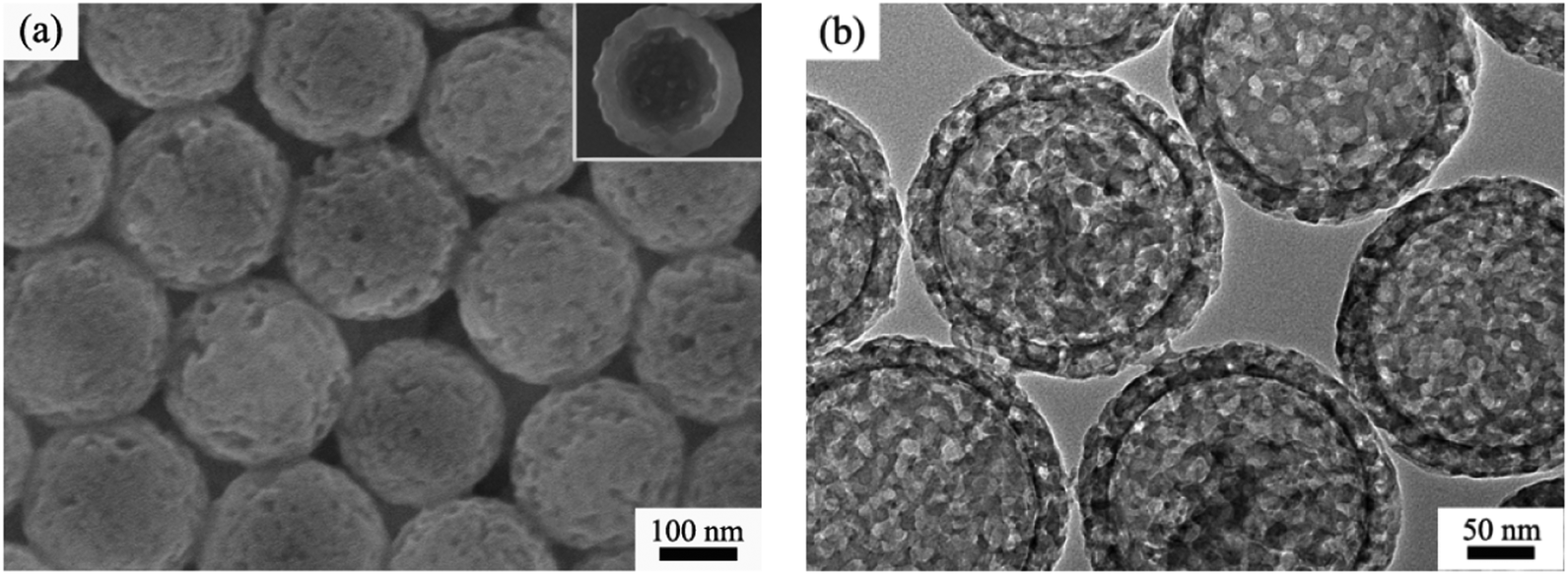 | ||
| Fig. 1 (a) FESEM and (b) TEM images of the as-prepared hm-SiO2 spheres; the inset showing the morphology of a broken nanosphere. | ||
The approach involves a sequential reaction process (Scheme 1). The dispersed hm-SiO2 nanospheres in an alcohol solution possess negatively charged surfaces with a zeta potential of –29.7 mV, capable of effectively adsorbing positively charged ions. As such, the added Ag+ ions are enriched on the surface of the hm-SiO2 nanospheres via electrostatic attractions. The precipitation of AgI NPs on the outer surface of the hm-SiO2 nanospheres occurs when I− is added (Fig. S3, ESI†). The impregnation of Ag NPs inside the hm-SiO2 nanospheres is achieved by hydroquinone reduction of dissolved Ag+ (from AgI) diffusing into the hm-SiO2 nanospheres (Scheme 1). Fig. 2a shows the TEM image of the resulting Y/S structured Ag@hm-SiO2 nanospheres. Each hm-SiO2 nanosphere encapsulates 5–10 Ag NP yolks in a monodisperse form (Fig. S4, ESI†). The Ag NP yolks are spherical in shape and sized from 12 to 28 nm with an average diameter of 20 nm (Fig. 2b). There are no obvious changes in the structural parameters of the hm-SiO2 nanospheres before and after impregnation of Ag NPs. Fig. 2c shows the EDX elemental mapping of Si, O, and Ag in a representative Ag@hm-SiO2 nanosphere. The profiles of Si and O are totally coincidental and both are uniformly distributed throughout the entire spherical structure. Nevertheless, the distribution of Ag is found to be confined within the hollow inner space of the sphere. The discontinued distribution of Ag within the hollow inner space is resulted from the encapsulated Ag being in separated NP forms. These results categorically confirm that multiple Ag NPs are successfully encapsulated inside hm-SiO2 nanospheres, in which the encapsulated Ag content is determined by ICP-OES to be 3.6 wt%.
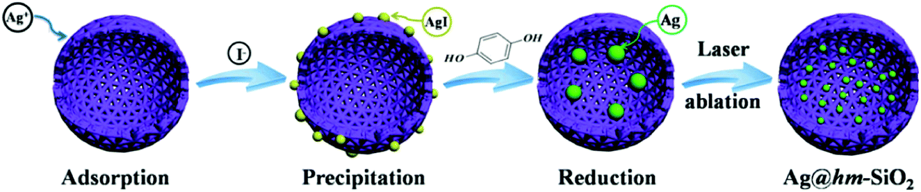 | ||
| Scheme 1 Schematic illustration of the synthetic route of Ag@hm-SiO2 nanoarchitectures. | ||
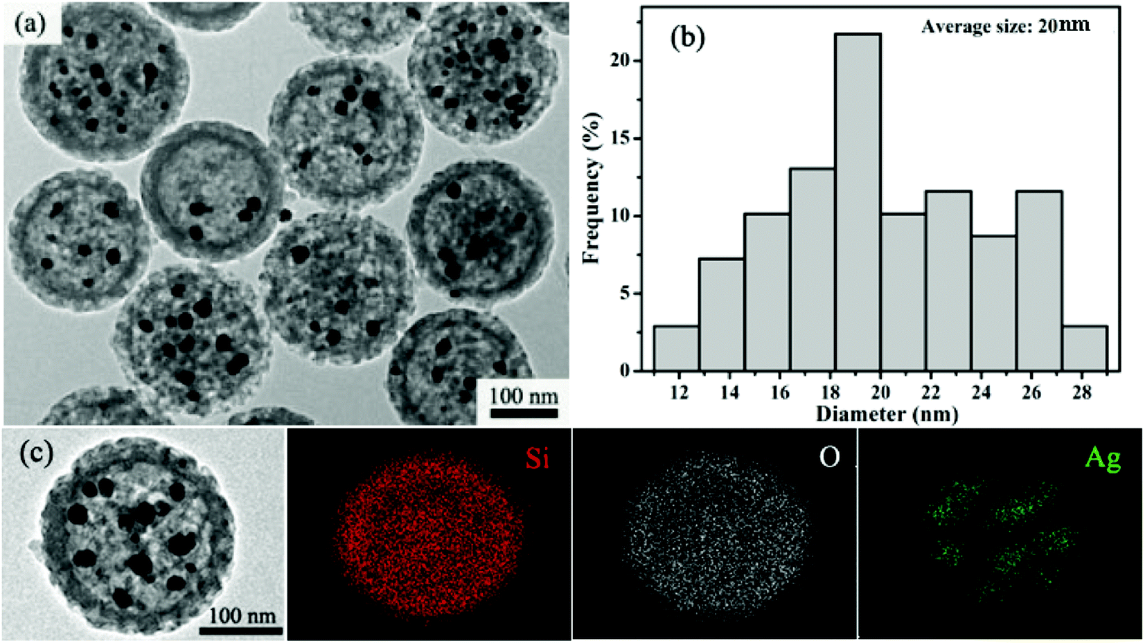 | ||
| Fig. 2 (a) A typical TEM image of Ag@hm-SiO2 nanoarchitectures with the multiple-core/shell configuration; (b) the corresponding size distribution of silver cores from the TEM image; (c) TEM image of a single Ag@hm-SiO2 sphere and EDX elemental mapping of Si, O and Ag. | ||
The above results demonstrate that the new sequential impregnation approach is capable of in situ encapsulating multiple Ag NP yolks into hm-SiO2 nanospheres. Mechanistically, the concentration gradients of hydroquinone and Ag+ between the outer and inner hm-SiO2 shells are the main driving force for the impregnation process of Ag NPs. The conversion of Ag+ into Ag by hydroquinone inside the hm-SiO2 nanospheres sustains the concentration gradients, enabling sufficient supply of silver sources for the growth of Ag NPs. It should be noted that the reduction of Ag+ by hydroquinone also occurs on the outer surface of the hm-SiO2 nanospheres and in the bulk solution as evidenced by the observed larger Ag particles precipitated from the reaction solution. No Ag NPs can be observed on the outer surface of the hm-SiO2 nanospheres due to the poor affinity of relatively large-sized Ag particles to the SiO2 surface. It should also be mentioned that the use of methanol as the reaction medium and the formation of AgI before the hydroquinone reduction process are critically important. In a pure aqueous system or in the absence of NaI, the attempts to impregnate Ag NPs inside hm-SiO2 nanospheres are not very successful due to the uncontrollable precipitation of Ag NPs. The slow release of Ag+ from AgI in methanol medium is crucial for incorporating Ag NPs into the hm-SiO2 nanosphere as it enables better control over the Ag precipitation process.
3.2. Laser ablation treatment of Ag@hm-SiO2 sphere nanoarchitectures
Although the above demonstrated impregnation method is effective for encapsulation of multiple Ag NP yolks inside the hm-SiO2 nanospheres, the encapsulated Ag NPs are relatively larger in size and fewer in number. For heterogeneous catalyses, a catalyst with a larger surface area tends to possess higher catalytic activity.4a,18 In order to improve the catalytic performance of Ag@hm-SiO2 nanospheres, it is necessary to develop a facile method capable of dramatically decreasing the size while simultaneously increasing the number of the encapsulated Ag NP yolks. It is well known that laser ablation is capable of reducing the particle size via melting–evaporation and laser-induced columbic explosion mechanisms.19 In this work, a facile laser ablation treatment is innovatively employed to achieve such a purpose. Fig. 3a shows a typical TEM image of Ag@hm-SiO2 nanospheres after 10 min laser ablation. As can be seen, the structural integrity of the laser treated hm-SiO2 nanospheres is well maintained and no noticeable changes in the shape, size and shell thickness can be observed. Additionally, the encapsulated Ag NP yolks in the treated sample exhibit dramatically reduced particle sizes and significantly increased particle numbers when compared with the untreated sample shown in Fig. 2a. The average particle size is reduced from ∼20 to ∼7 nm while the particle size distribution range changes from 12–28 to 3–13 nm, respectively (Fig. 3b). The numbers of the encapsulated Ag NP yolks concurrently increase from 5–10 to 90–150 (Fig. S5†). Importantly, the encapsulated Ag NP yolks are found to be uniformly distributed within the cavity of the hm-SiO2 nanospheres with very few being entered into the mesoporous shell.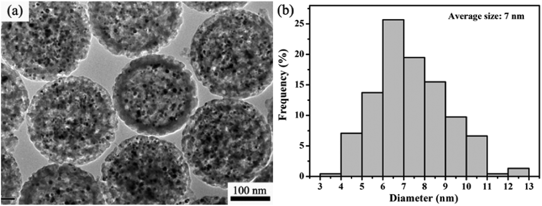 | ||
| Fig. 3 (a) TEM image of Ag@hm-SiO2 spheres after the treatment of laser ablation and (b) the size distribution histogram of silver cores from the TEM image in the left. | ||
The pore structure changes of the Ag@hm-SiO2 nanospheres after laser ablation treatment are examined by the N2 adsorption/desorption isotherms (Fig. S6, ESI†). The measured pore size distribution by the Barrett–Joyner–Halenda (BJH) method is almost identical to that obtained from Ag@hm-SiO2 nanospheres without laser ablation treatment. The laser ablation treatment results in slight changes in the BET surface area and pore volume of the Ag@hm-SiO2 nanospheres from 71 m2 g−1 and 0.47 cm3 g−1 to 73 m2 g−1 and 0.49 cm3 g−1, respectively. These observations suggest that the changes in pore structural characteristics caused by the laser ablation treatment are insignificant. The Ag contents of the Ag@hm-SiO2 nanospheres after laser ablation treatment are examined and a negligible change is obtained from the ICP-OES analysis. The above experimental results confirm that the damage induced by the laser ablation treatment to the Ag@hm-SiO2 nanosphere structure is minimal. It is expected that such a Y/S Ag@hm-SiO2 catalyst nanoarchitecture encapsulating large numbers of uniformly dispersed small Ag NP yolks will possess significantly enhanced catalytic activity than those encapsulating single or fewer larger-sized NPs.9c,20
3.3. Catalytic performance evaluation
The reduction of 4-NP in the presence of NaBH4 is chosen as a model reaction to evaluate the catalytic performance of Ag@hm-SiO2 nanoarchitectures before and after laser ablation treatment. The catalytic reduction of 4-NP to the corresponding amino derivatives is important for organic pollutant remediation and synthetic chemistry.21 The process of 4-NP catalytic reduction is monitored by UV–vis spectroscopy at 400 nm.22 Usually, 4-NP aqueous solution displays a strong absorption band at ca. 317 nm (Fig. S7a, ESI†). However, when NaBH4 is added to the 4-NP solution, a new absorption band centred at 400 nm appears due to the formation of a 4-nitrophenolate ion (Fig. S7b, ESI†).23 The absorption intensity at 400 nm remains unchanged in the absence of Ag@hm-SiO2 nanospheres, indicating that the reduction of 4-NP cannot proceed in the absence of Ag catalysts (Fig. S7b, ESI†). When the as-synthesized Ag@hm-SiO2 nanospheres are added to a reaction solution containing 4-NP and NaBH4 with the desired concentrations, the catalytic reduction of 4-NP into 4-aminophenol (4-AP) takes place as evidenced by the decreased peak intensity at 400 nm resulting from the decreased 4-NP concentration and the increased peak intensity at 296 nm corresponding to the formation of 4-AP (Fig. 4a).24 The absorption peak at 400 nm disappears after 13 min, indicating complete conversion of 4-NP into 4-AP. Under the same experimental conditions, it takes only 5 min to complete the conversion when the same amount of Ag@hm-SiO2 nanospheres treated by laser ablation is used to replace the as-synthesized Ag@hm-SiO2 nanospheres, indicating an enhanced catalytic performance (Fig. 4b). Fig. 4c shows the plots of the 4-NP concentration ratio against the reaction time. A linear relationship between ln(Ct/C0) and the reaction time can be derived from the data presented in Fig. 4c, as shown in Fig. 4d, suggesting a first-order reaction kinetics. The calculated first-order rate constants (k) are found to be 0.38 and 1.08 min−1 for the as-synthesized and the laser ablation treated Ag@hm-SiO2 nanospheres, respectively, exceeding the other reported catalysts (see Table S1, ESI†).4a,25 Such a noticeably enhanced catalytic activity can be attributed to the significantly increased active surface area of the Ag catalyst, resulting from the dramatically reduced size and increased number of the encapsulated Ag NPs.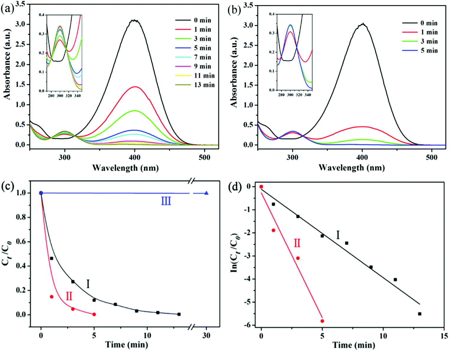 | ||
| Fig. 4 (a) and (b): Time-dependent UV-vis spectra of 4-NP reduced by Ag@hm-SiO2 catalysts before and after laser ablation in the presence of NaBH4, respectively; (c) and (d): Ct/C0 and the corresponding linear fits versus time in the presence of different catalysts, respectively: (I) Ag@hm-SiO2 before laser ablation; (II) Ag@hm-SiO2 after laser ablation; (III) without any catalyst. | ||
In addition to the catalytic activity, the reusability and stability of the laser ablation treated Ag@hm-SiO2 nanospheres are also evaluated over 6 successive catalytic cycles. The Ag@hm-SiO2 nanospheres are separated from the reaction solution and washed with ethanol and deionized water between the cycles. The results confirm that no noticeable catalytic activity decays within the six consecutive catalytic cycles (Fig. 5a), indicating superior reusability and excellent stability. More importantly, no morphology or size changes and particle aggregation can be observed from the laser ablation treated Ag@hm-SiO2 nanospheres after six consecutive catalytic cycles (Fig. 5b), further confirming the superior stability of the obtained catalysts. This could be attributed to the effective protection provided by the hm-SiO2 shell.3a,26
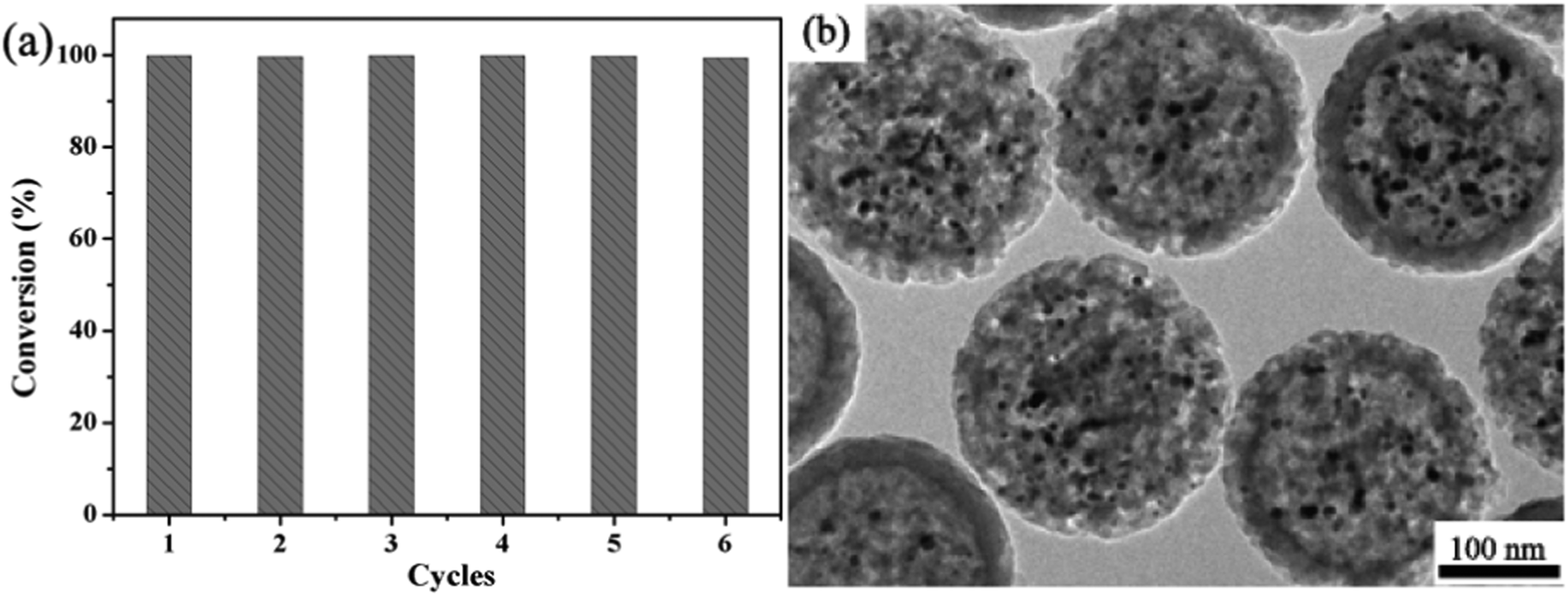 | ||
| Fig. 5 (a) Conversions of 4-NP in six successive cycles with Ag@hm-SiO2 catalysts (after laser ablation) and (b) the TEM image of the retrieved Ag@hm-SiO2 samples after the sixth cycle. | ||
4. Conclusion
In summary, a sophisticated Ag@hm-SiO2 nanoarchitecture made of a mesoporous shell and a large number of Ag NP yolks has been successfully fabricated by combining the pre-shell/post-core synthetic approach with laser ablation treatment. The experimental results confirm that the in situ impregnation approach is effective for encapsulating multiple Ag NPs into the hm-SiO2 nanospheres while the laser ablation treatment is capable of dramatically reducing the sizes of the encapsulated Ag NPs and increasing their numbers. The fabricated Ag@hm-SiO2 nanoarchitectures possess high catalytic activity towards 4-NP reduction and superior stability, which can be attributed to the excellent mass transport and catalyst protection functionalities of the mesoporous shell as well as the abundant active sites from a large number of encapsulated Ag NPs. The findings of this work demonstrate that high speed, selectivity and stability catalysts can be holistically achieved through the development of sophisticated catalyst architectures.Acknowledgements
The authors gratefully acknowledge the financial support from the National Basic Research Program of China (Grant No. 2013CB934302), the National Natural Science Foundation of China (Grant No. 51272255, 51572263, 51502298, 51472246) and the CAS/SAFEA International Partnership Program for Creative Research Teams of Chinese Academy of Sciences, China.Notes and references
- (a) N. R. Shiju and V. V. Guliants, Appl. Catal., A, 2009, 356, 1 CrossRef CAS; (b) Z. C. Zhang, B. Xu and X. Wang, Chem. Soc. Rev., 2014, 43, 7870 RSC; (c) D. Wang, T. Xie and Y. Li, Nano Res., 2010, 2, 30 CrossRef; (d) Y. Dai, Y. Wang, B. Liu and Y. Yang, Small, 2015, 11, 268 CrossRef CAS PubMed.
- A. Corma and H. Garcia, Chem. Soc. Rev., 2008, 37, 2096 RSC.
- (a) J. C. Park and H. Song, Nano Res., 2010, 4, 33 CrossRef; (b) T. Yao, T. Cui, X. Fang, F. Cui and J. Wu, Nanoscale, 2013, 5, 5896 RSC.
- (a) L. Shi, M. Liu, L. Liu, W. Gao, M. Su, Y. Ge, H. Zhang and B. Dong, Langmuir, 2014, 30, 13456 CrossRef CAS PubMed; (b) K.-i. Shimizu, Y. Miyamoto and A. Satsuma, J. Catal., 2010, 270, 86 CrossRef CAS; (c) H. Yang, Y. Kwon, T. Kwon, H. Lee and B. J. Kim, Small, 2012, 8, 3161 CrossRef CAS PubMed; (d) S. Q. Zhou, S. Bai, E. J. Cheng, R. Qiao, Y. Xie and Z. Q. Li, Inorg. Chem. Front., 2015, 2, 938 RSC.
- (a) S. H. Joo, J. Y. Park, C.-K. Tsung, Y. Yamada, P. Yang and G. A. Somorjai, Nat. Mater., 2009, 8, 126 CrossRef CAS PubMed; (b) J. Ge, Q. Zhang, T. Zhang and Y. Yin, Angew. Chem., Int. Ed., 2008, 47, 8924 CrossRef CAS PubMed; (c) J. Y. Kim, S. B. Yoon and J. S. Yu, Chem. Commun., 2003, 6, 790 RSC.
- (a) J. Liu, S. Z. Qiao, J. S. Chen, X. W. Lou, X. Xing and G. Q. Lu, Chem. Commun., 2011, 47, 12578 RSC; (b) N. Zhang, X. Fu and Y.-J. Xu, J. Mater. Chem., 2011, 21, 8152 RSC; (c) J. Han, L. Wang and R. Guo, J. Mater. Chem., 2012, 22, 5932 RSC.
- C. Liu, J. Li, J. Qi, J. Wang, R. Luo, J. Shen, X. Sun, W. Han and L. Wang, ACS Appl. Mater. Interfaces, 2014, 6, 13167 CAS.
- (a) C. Galeano, R. Guttel, M. Paul, P. Arnal, A. H. Lu and F. Schuth, Chemistry, 2011, 17, 8434 CrossRef CAS PubMed; (b) S. Ikeda, S. Ishino, T. Harada, N. Okamoto, T. Sakata, H. Mori, S. Kuwabata, T. Torimoto and M. Matsumura, Angew. Chem., Int. Ed., 2006, 45, 7063 CrossRef CAS PubMed.
- (a) J. Liu, H. Q. Yang, F. Kleitz, Z. G. Chen, T. Yang, E. Strounina, G. Q. M. Lu and S. Z. Qiao, Adv. Funct. Mater., 2012, 22, 591 CrossRef CAS; (b) M. Xiao, C. Zhao, H. Chen, B. Yang and J. Wang, Adv. Funct. Mater., 2012, 22, 4526 CrossRef CAS; (c) Z. Chen, Z. M. Cui, F. Niu, L. Jiang and W. G. Song, Chem. Commun., 2010, 46, 6524 RSC.
- (a) X. Fang, X. Zhao, W. Fang, C. Chen and N. Zheng, Nanoscale, 2013, 5, 2205 RSC; (b) F. Hu, Y. Zhang, G. Chen, C. Li and Q. Wang, Small, 2015, 11, 985 CrossRef CAS PubMed.
- H. Pang, P. Cheng, H. Yang, J. Lu, C. X. Guo, G. Ning and C. M. Li, Chem. Commun., 2013, 49, 1536 RSC.
- (a) Y. Yin, R. M. Rioux, C. K. Erdonmez, S. Hughes, G. A. Somorjai and A. P. Alivisatos, Science, 2004, 304, 711 CrossRef CAS PubMed; (b) L. Cao, D. Chen and R. A. Caruso, Angew. Chem., Int. Ed., 2013, 52, 10986 CrossRef CAS PubMed.
- M. Y. Son, Y. J. Hong and Y. C. Kang, Chem. Commun., 2013, 49, 5678 RSC.
- (a) Y. Yang, X. Liu, X. Li, J. Zhao, S. Bai, J. Liu and Q. Yang, Angew. Chem., Int. Ed., 2012, 51, 9164 CrossRef CAS PubMed; (b) Y. Zhang, S. Xu, Y. Luo, S. Pan, H. Ding and G. Li, J. Mater. Chem., 2011, 21, 3664 RSC; (c) W. Li, Y. Deng, Z. Wu, X. Qian, J. Yang, Y. Wang, D. Gu, F. Zhang, B. Tu and D. Zhao, J. Am. Chem. Soc., 2011, 133, 15830 CrossRef CAS PubMed; (d) X. Huang, C. Guo, J. Zuo, N. Zheng and G. D. Stucky, Small, 2009, 5, 361 CrossRef CAS PubMed; (e) D. Bhattacharjya, M. S. Kim, T. S. Bae and J. S. Yu, J. Power Sources, 2013, 244, 799 CrossRef CAS.
- (a) H. J. Hah, J. I. Um, S. H. Han and S. M. Koo, Chem. Commun., 2004, 8, 1012 RSC; (b) D. H. Liu, Y. Guo, L. H. Zhang, W. C. Li, T. Sun and A. H. Lu, Small, 2013, 9, 3852 CrossRef CAS PubMed; (c) L. Tan, D. Chen, H. Liu and F. Tang, Adv. Mater., 2010, 22, 4885 CrossRef CAS PubMed; (d) D. Cheng, X. Zhou, H. Xia and H. S. O. Chan, Chem. Mater., 2005, 17, 3578 CrossRef CAS.
- (a) Y. Chen, C. Chu, Y. Zhou, Y. Ru, H. Chen, F. Chen, Q. He, Y. Zhang, L. Zhang and J. Shi, Small, 2011, 7, 2935 CrossRef CAS PubMed; (b) Y. Chen, H. Chen, L. Guo, Q. He, F. Chen, J. Zhou, J. Feng and J. Shi, ACS Nano, 2010, 4, 529 CrossRef CAS PubMed.
- K. Zhang, H. Chen, Y. Zheng, Y. Chen, M. Ma, X. Wang, L. Wang, D. Zeng and J. Shi, J. Mater. Chem., 2012, 22, 12553 RSC.
- (a) R. A. Van Santen, Acc. Chem. Res., 2008, 42, 57 CrossRef PubMed; (b) D. Y. Murzin, J. Mol. Catal. A: Chem., 2010, 315, 226 CrossRef CAS; (c) T. Zhang, H. Zhao, S. He, K. Liu, H. Liu, Y. Yin and C. Gao, ACS Nano, 2014, 8, 7297 CrossRef CAS PubMed.
- H. Zeng, X. W. Du, S. C. Singh, S. A. Kulinich, S. Yang, J. He and W. Cai, Adv. Funct. Mater., 2012, 22, 1333 CrossRef CAS.
- (a) B. Liu, W. Zhang, H. Feng and X. Yang, Chem. Commun., 2011, 47, 11727 RSC; (b) X. W. Lou, C. Yuan, E. Rhoades, Q. Zhang and L. A. Archer, Adv. Funct. Mater., 2006, 16, 1679 CrossRef CAS.
- A. M. Tafesh and J. Weiguny, Chem. Rev., 1996, 96, 2035 CrossRef CAS PubMed.
- (a) Y. Qiu, Z. Ma and P. Hu, J. Mater. Chem. A, 2014, 2, 13471 RSC; (b) F. Lin and R. Doong, J. Phys. Chem. C, 2011, 115, 6591 CrossRef CAS.
- (a) W. Lu, R. Ning, X. Qin, Y. Zhang, G. Chang, S. Liu, Y. Luo and X. Sun, J. Hazard. Mater., 2011, 197, 320 CrossRef CAS PubMed; (b) Y. Zhang, S. Liu, W. Lu, L. Wang, J. Tian and X. Sun, Catal. Sci. Technol., 2011, 1, 1142 RSC.
- (a) Y. Zhang, X. Yuan, Y. Wang and Y. Chen, J. Mater. Chem., 2012, 22, 7245 RSC; (b) G. Chang, Y. Luo, W. Lu, X. Qin, A. M. Asiri, A. O. Al-Youbi and X. Sun, Catal. Sci. Technol., 2012, 2, 800 RSC.
- (a) A. K. Ganai, P. Shinde, B. B. Dhar, S. Sen Gupta and B. L. V. Prasad, RSC Adv., 2013, 3, 2186 RSC; (b) B. C. Liu, Q. Wang, S. L. Yu, P. Jing, L. X. Liu, G. R. Xu and J. Zhang, Nanoscale, 2014, 6, 11887 RSC; (c) W. Xiao, Y. H. Zhang and B. T. Liu, ACS Appl. Mater. Interfaces, 2015, 7, 6041 CrossRef CAS PubMed; (d) N. J. Hao, L. F. Li and F. Q. Tang, J. Mater. Chem. A, 2014, 2, 11565 RSC; (e) X. F. Qian, Y. Kuwahara, K. Mori and H. Yamashita, Chem. – Eur. J., 2014, 20, 15746 CrossRef CAS PubMed; (f) X. Guo, Q. Zhang, Y. H. Sun, Q. Zhao and J. Yang, ACS Nano, 2012, 6, 1165 CrossRef CAS PubMed; (g) Q. Zhang, X. Z. Shu, J. M. Lucas, F. D. Toste, G. A. Somorjai and A. P. Aivisatos, Nano Lett., 2014, 14, 379 CrossRef CAS PubMed; (h) J. Han, M. G. Wang, R. Chen, N. Han and R. Guo, Chem. Commun., 2014, 50, 8295 RSC; (i) L. Huang, L. J. Ao, X. B. Xie, G. H. Gao, M. F. Foda and W. Su, Nanoscale, 2015, 7, 806 RSC; (j) H. B. Zou, R. W. Wang, X. X. Li, X. Wang, S. J. Zeng, S. Ding, L. Li, Z. T. Zhang and S. L. Qiu, J. Mater. Chem. A, 2014, 2, 12403 RSC.
- M. Simões, S. Baranton and C. Coutanceau, J. Phys. Chem. C, 2009, 113, 13369 Search PubMed.
Footnotes |
| † Electronic supplementary information (ESI) available: N2 adsorption/desorption isotherms of the as-prepared hm-SiO2 spheres; SEM image and EDS analysis of the deposition of AgI NPs on the hm-SiO2 spheres outer surfaces; Ag NP numbers in an individual Ag@hm-SiO2 sphere; N2 adsorption/desorption isotherms of the Ag@hm-SiO2 spheres before and after laser ablation treatment. See DOI: 10.1039/c6qi00002a |
| ‡ These authors contributed equally to this work. |
| This journal is © the Partner Organisations 2016 |