Molecular photo-charge-separators enabling single-pigment-driven multi-electron transfer and storage leading to H2 evolution from water†
Kyoji
Kitamoto
ab,
Makoto
Ogawa‡
a,
Gopalakrishnan
Ajayakumar§
a,
Shigeyuki
Masaoka¶
a,
Heinz-Bernhard
Kraatz
cd and
Ken
Sakai
*abe
aDepartment of Chemistry, Faculty of Science, Kyushu University, 744 Motooka, Nishi-ku, Fukuoka 819-0395, Japan. E-mail: ksakai@chem.kyushu-univ.jp
bInternational Institute for Carbon-Neutral Energy Research (WPI-I2CNER), Kyushu University, 744 Motooka, Nishi-ku, Fukuoka 819-0395, Japan
cDepartment of Physical and Environmental Sciences, University of Toronto Scarborough, 1265 Military Trail, Toronto, Ontario M1C 1A4, Canada
dDepartment of Chemistry, University of Toronto, 80 St. George Street, Toronto, Ontario M5S 3H6, Canada
eCenter for Molecular Systems (CMS), Kyushu University, 744 Motooka Nishi-ku, Fukuoka 819-0395, Japan
First published on 8th February 2016
Abstract
Single-chromophore-driven single-electron-pumping processes leading to multi-electron transfer and storage are effectively promoted in natural photosynthesis, generating photocurrent at the molecular level. Moreover, these single-electron-pumping events are converted into double-electron-pumping events by releasing multiple plastoquinol molecules without releasing reactive semiquinone radicals, thereby enabling storage of two-electron-reduced molecules within the lipid bilayer constructing the thylakoid membrane. Here we report new unimolecular architectures that enable these highly sophisticated light-driven multi-electron transfer and storage processes. The photo-charge-separators (PCSs) reported herein possess a single Ru(bpy)32+ fragment with each bpy derivatized with four dicationic viologen acceptors, abbreviated as [RuII(bpy)32+–(MV2+)12]26+ (MV2+ is a viologen unit). These highly positively charged PCSs form stable ion pairs with anionic electron donors, enabling consecutive multi-electron transfer processes from the donors to the pendant viologen acceptors. The multiple transferred electrons are collected over twelve pendant viologen acceptors, leading to storage of 7–8 electrons per molecule. The resulting organic radicals show a strong preference to form diamagnetic π-dimers, which suppress reactive radical formation. These reducing equivalents can then be efficiently consumed in catalytic H2 evolution from water in the presence of a colloidal platinum catalyst.
Introduction
The photosynthetic reaction centers of green plants consist of two light-harvesting proteins PSI and PSII, which work together to generate high-energy products (ATP and NADPH) by absorbing sunlight based on a Z scheme. During photosynthesis, electrons are first catalytically extracted from water at the oxygen-evolving Mn4CaO5 cluster in PSII,1 producing O2 as a byproduct (2H2O + 4hν → O2 + 4H+ + 4e−). Part of the energy gained at PSII is then consumed to transport electrons from PSII to PSI, and the transferred electrons are re-excited to higher energies to generate NADPH by formal hydride addition to NADP+ (H+ + 2e− → H–, and NADP+ + H− → NADPH).2 Since this process has strong similarities to water reduction (2H+ + 2e− → H2), the oxygenic photosynthesis of green plants is considered an important model of solar-driven water splitting into H2 and O2. Both PSII and PSI possess a primary donor pigment (P; a special dimer of chlorophylls) closely associated with primary electron acceptors (A; pheophytin). Upon solar light irradiation, P is promoted to an excited state P* leading to rapid electron transfer (ET) from P* to A, giving rise to a charge separated (CS) state (P+˙–A−˙). Thus, the photocurrent generated during photosynthesis is the result of a rapid repetition of the same ET events at a single pigment P on the basis of a single-pigment-driven single-electron-pumping scheme. Moreover, natural photosynthesis stores multiple electrons in the quinone pool by converting plastoquinone (Q) into plastoquinol (H2Q). When electrons are released from PSII, two electrons are always released in the form of plastoquinol (H2Q; Q + 2H+ + 2e− → H2Q) without ejecting a highly reactive semiquinone radical (HQ˙, given from Q + H+ + e−) so that undesirable side reactions are suppressed. Moreover, the high turnover frequency of O2 evolution (100–400 s−1)3 must be synchronized with the double-electron-pumping events, corresponding to the release of H2Q.Inspired by such behaviors in natural photosynthesis, extensive efforts have been made to invent artificial photosynthetic devices.4–15 Although various donor–acceptor systems affording a long-lived CS state have been developed,14 none of them are capable of storing and/or transporting more than two electrons over multiple acceptors introduced within a unimolecular architecture. Some reports showed that a molecular catalyst can work together with a photosensitizer to demonstrate two consecutive one-electron photoreductions at the catalyst core, and thus given two-electron-reduced species can drive H2 evolution from water,10,13 even though these do not fall into a category of the mimics of multi-electron charging in the quinone pool. Further, consecutive two one-electron transfers within a [Ru(bpy)(phen)(CN)2]-anchored TiO2 system were demonstrated,15 in which not more than two electrons could be pumped using a single dye. Here we demonstrate that more than 6 or 7 electrons can be charged within a unimolecular photo-charge-separator (PCS) which consists of a single dye tethered to twelve acceptor sites. Using our PCSs, single-pigment-driven multi-electron transfer and storage can be promoted. The PCSs can also synchronize single-electron-pumping events with double-electron-storage events within its framework, which ultimately results in double-electron-consumption events corresponding to catalytic H2 evolution from water.
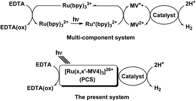
Our systems employ the Ru(bpy)32+ (bpy = 2,2′-bipyridine) dye which has attracted considerable attention due to its potential application in solar-driven water splitting.16 Its practical use has been extensively investigated in a photo-driven H2 evolution system consisting of [Ru(bpy)3]2+ (photosensitizer), methyl viologen (MV2+; N,N′-dimethyl-4,4′-bipyridinium; electron relay), and an H2-evolving catalyst, such as a colloidal Pt or a molecular catalyst of either Pt, Rh, or Co (see Scheme 1),17–21 where EDTA (ethylenediaminetetraacetic acid disodium salt; Na2YH2) is added as a sacrificial electron source to study the photocatalytic efficiency of an individual system. The PCSs possess a single Ru(bpy)32+ fragment with each x,x′-substituted bpy derivative tethered to four pendant viologen moieties (abbreviated as x,x′-MV48+, where x = 4 or 5) and are formulated as [Ru(x,x′-MV4)3]26+ (see Fig. 1). This study also employs a control system having a single 5,5′-MV48+ chelate, i.e., [Ru(bpy)2(5,5′-MV4)]10+ (see Fig. 1), which is much less efficient in photo-driven multi-electron transfer and storage as well as in photocatalytic H2 evolution.22 Although a relatively large number of Ru(bpy)32+–(MV2+)n dyads have been reported to date,22–28 our PCSs exhibit outstanding performance in single-pigment-driven multi-electron transfer and storage. As described below, the efficiency results from its highly positively charged character which enables ion-pair formation with anionic EDTA, together with its ability to form diamagnetic π-dimers (MV+)2, which enables double-electron storage coupled with catalytic H2 evolution from water.
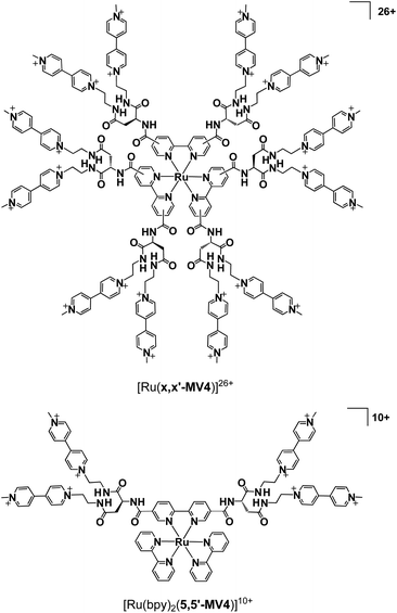 | ||
| Fig. 1 Structures of [Ru(x,x′-MV4)3]26+ (x = 4 or 5; x denotes the positions where substituents are connected), together with that of a control system [Ru(bpy)2(5,5′-MV4)]10+. | ||
Results and discussion
Ion-pair formation of PCSs with anionic species in solution
As discussed above, the PCSs owe their efficient performance to their high positive charge (i.e., 26+), which enables effective collection of anionic electron donors within their frameworks. Under the pH conditions employed in the following studies, the dianionic form of EDTA (i.e., YH22–; 93% in abundance at pH 5.0) is the major species in solution.29 Rapid consecutive regeneration of the central pigment after its one-electron oxidation, or even rapid consecutive reductive quenching upon photoexcitation, can be greatly enhanced by ion-pair formation between the PCS cation and the YH22– anions. Evidence for the high capacity of the PCSs to collect anionic species has been afforded by simple molar conductivity measurements. The PCSs are moderately soluble in aqueous media in spite of their high charge. The concentration dependence of the molar conductivity shows a clear increase in molar conductivity at lower total PCS concentrations (Fig. S1†), attributable to the higher relative abundance of more highly charged species at lower total PCS concentrations. Based on our published procedures,22 it can be roughly estimated that ion-pair adducts {[Ru(4,4′-MV4)3](PF6)n}(26−n)+ with n = 9 (3.1%), 10 (9.3%), 11 (18.6%), 12 (25.0%), 13 (22.5%), 14 (13.5%), 15 (5.5%), and 16 (1.5%) are major chemical species in solution at a total concentration of 0.04 mM, where the value in each parenthesis corresponds to the relative abundance of the ion-pair adducts. Similarly, ion-pair adducts {[Ru(5,5′-MV4)3](PF6)n}(26−n)+ with n = 9–16 are shown to be the major species under the same conditions (Table S3†). The space-filling model computed for the adduct holding twelve PF6– anions is exemplified in Fig. 2 (see also Fig. S3†). The stepwise ion-pair formation constants K1–K14 are in the range of ca. 103–105 M−1 (Table S2†), considerably larger than the value of K1 = 16 M−1 recently determined for the ion-pair formation between a dicationic RuPt-based H2-evolving molecular photocatalyst and YH22– under similar conditions.30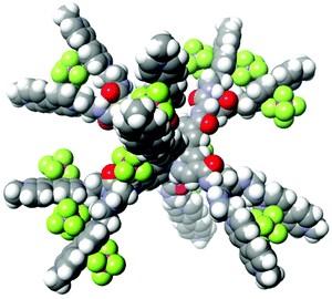 | ||
| Fig. 2 The space-filling model computed for one of the ion-pair adducts, {[Ru(4,4′-MV4)3](PF6)12}14+ (computed by MM3). | ||
Photo-driven forward and backward electron transfer processes in PCSs
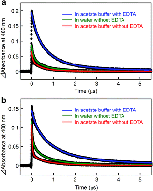
A metal-to-ligand charge transfer (1MLCT) transition, characteristic of the RuII(bpy)32+ fragment,16 is observed at 468 nm for [Ru(4,4′-MV4)3]26+ and 490 nm for [Ru(5,5′-MV4)3]26+ (Fig. S4a†). An extremely weak phosphorescence from the triplet (3MLCT state) is observable at 630 nm for [Ru(4,4′-MV4)3]26+ and 670 nm for [Ru(5,5′-MV4)3]26+, with which their emission quantum yields are determined to be 0.002 and 0.001, respectively (Fig. S4b and Table S4†). These quantum yields are much lower than that reported for [Ru(bpy)3]2+ (0.042),16 primarily due to the intramolecular ET from the Ru*(bpy)32+ core to the viologen tethers in the absence of EDTA (i.e., oxidative quenching; Scheme 2). The CS(1) state ([RuIII(bpy)33+–(MV+˙)(MV2+)11]26+) can be observed as positive absorption at 400 and 600 nm, corresponding to monoradical MV+˙,31 using laser flash photolysis (Fig. S5–S7†). There is a clear tendency that the overlap of absorption by the MV+˙ and triplet species becomes more severe as the quenching efficiency becomes smaller. In the absence of EDTA (Fig. 3), regardless of the presence of acetate buffer reagents, the initial shorter-lived decay components (τem's in Table 1) are assigned as those of the triplet, while longer-lived components (τCS,1–τCS,3 in Table 1) are those due to back electron transfer (BET(1) in Scheme 2).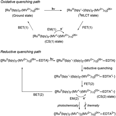 | ||
| Scheme 2 Photoinduced electron transfer processes in PCSs. Oxidative and reductive quenching paths are shown. | ||
| Constant | [Ru(4,4′-MV4)3]26+ | [Ru(5,5′-MV4)3]26+ |
|---|---|---|
| a Estimated from the transient absorption decays at 400 nm. b Each net CS lifetime (<τCS>) was estimated using an equation <τCS> = ∑aiτi2/∑aiτi, where ai is the relative contribution of each component with lifetime τi. c <kBET> = 1/<τCS>. d Determined from the emission decay at 630 and 670 nm for [Ru(4,4′-MV4)3]26+ and [Ru(5,5′-MV4)3]26+, respectively. | ||
| In water | ||
| CS(1) lifetimesa | τ em = 25.5 ns (12.1%) | τ em = 21.1 ns (35.3%) |
| τ CS,1 = 107 ns (39.0%) | τ CS,1 = 123 ns (23.8%) | |
| τ CS,2 = 579 ns (41.6%) | τ CS,2 = 688 ns (33.2%) | |
| τ CS,3 = 1.53 μs (7.3%) | τ CS,3 = 1.94 μs (7.7%) | |
| Net CS lifetimeb | <τCS> = 800 ns | <τCS> = 1.11 μs |
| Net BET ratec | <kBET> = 1.25 × 10⁶ s−1 | <kBET> = 9.03 × 10⁵ s−1 |
| In acetate buffer solution in the absence of EDTA | ||
| CS(1) lifetimesa | τ em = 43.3 ns (38.9%) | τ em = 27.4 ns (73.5%) |
| τ CS,1 = 264 ns (26.9%) | τ CS,1 = 196 ns (5.1%) | |
| τ CS,2 = 502 ns (29.2%) | τ CS,2 = 695 ns (18.7%) | |
| τ CS,3 = 1.46 μs (5.0%) | τ CS,3 = 2.06 μs (2.7%) | |
| Net CS lifetimeb | <τCS> = 650 ns | <τCS> = 959 ns |
| Net BET ratec | <kBET> = 1.54 × 10⁶ s−1 | <kBET> = 1.04 × 10⁶ s−1 |
| In acetate buffer solution in the presence of EDTA (30 mM) | ||
| CS(2) lifetimesa | τ CS,1 = 242 ns (26.9%) | τ CS,1 = 181 ns (17.8%) |
| τ CS,2 = 624 ns (30.5%) | τ CS,2 = 743 ns (47.3%) | |
| τ CS,3 = 1.43 μs (42.6%) | τ CS,3 = 1.97 μs (34.9%) | |
| Net CS lifetimeb | <τCS> = 1.05 μs | <τCS> = 1.51 μs |
| Net BET ratec | <kBET> = 9.52 × 10⁵ s−1 | <kBET> = 6.62 × 10⁵ s−1 |
| Time constants for FET(1)d | τ 1 = 2.72 ns (13.1%) | τ 1 = 1.86 ns (7.8%) |
| τ 2 = 10.9 ns (71.0%) | τ 2 = 8.35 ns (29.8%) | |
| τ 3 = 25.2 ns (15.9%) | τ 3 = 17.1 ns (62.4%) | |
Importantly, in the presence of EDTA, the yield of MV+˙ is dramatically increased (Fig. 3) and the decay does not involve any triplet component (Table 1, Fig. S5 and S6†). These results clearly indicate that the reductive quenching, affording the CS(2) state in Scheme 2, is a major quenching path when the YH22– anions are ion-paired within the PCS framework. An important feature common to all six experiments in Fig. 3 is a nearly quantitative recombination of either the CS(1) or CS(2) state. An almost quantitative recombination of the CS(2) state reveals that thermal electron injection from EDTA+˙ to either RuII(bpy)32+ or MV2+ does not occur, consistent with the previous observation for the TEOA/[Ru(bpy)3]2+/MV2+ system at pH 5 (recombination is pH-dependent and hindered at pH 7).32 We thus conclude that the double-electron-pumping event demonstrated below using EDTA primarily occurs via two one-electron transfer steps based on two consecutive photoinduced ET processes (i.e., 2hν + 2MV2+ + EDTA → 2MV+˙ + EDTA2+). In other words, one-photon double-electron-charging (i.e., 1hν + 2MV2+ + EDTA → 2MV+˙ + EDTA2+) has a minor contribution to the charge storage of PCSs under these conditions.
For both PCSs under any condition, the major CS(1) or CS(2) lifetimes (Table 1) are clearly longer than that reported for [Ru(bpy)2(5,5′-MV4)]10+ (20 ns, in water without EDTA).22 These data reveal that BET is considerably hindered in these PCSs, possibly due to their higher probability for electron migration (EM; see Scheme 2). Our molecular modeling studies (e.g., Fig. 2 and S3†) clearly reveal that ET between two adjacent viologen moieties is possible, allowing EM over the pseudo-spherical viologen network. From a statistical viewpoint, it is quite reasonable to consider that the probability of BET is diminished by increasing the probability of passing the transferred electron among the neighboring viologen moieties. Fig. 4a illustrates our model used to simulate CS(1) lifetimes based on a Monte Carlo technique. This model supposes that one branch interacts with two equivalent branches with each branch having two MV2+ units. After establishing a CS(1) state, three types of ET events, i.e., intra-branch ET, inter-branch ET, and BET events, may occur, where any intra- or inter-branch ET event is supposed to recover an identical CS(1) state and thus regarded as an EM(1) event. By tuning the probability parameters defined for all these possible ET events, CS lifetimes for a hundred thousand of PCS molecules can be computed by using a simple Monte Carlo technique, where parameters have been tuned so that the simulated CS decay profiles show rough consistency with the observed profiles (Fig. 4b; see ESI† for the details). The results well rationalize why the CS lifetime increases as the number of viologen units gathered in a local geometry is increased. The simulation of CS(2) lifetimes is not straightforward due to the lack of an appropriate model. However, longer CS(2) lifetimes are similarly rationalized in terms of the enhancement of EM(2) in Scheme 2.
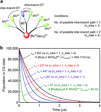 | ||
| Fig. 4 (a) A model used to compute the CS(1) lifetimes in our Monte Carlo simulation, where n_intra denotes the number of adjacent viologen units within the branch involving the MV+˙ site, and n_inter denotes the number of equivalent adjacent branches available for ET. (b) CS(1) decay profiles predicted based on a Monte Carlo simulation technique, where the defined parameters were tuned to roughly regenerate the observed CS(1) lifetimes. See the ESI† for details. | ||
On the other hand, the time constants for the forward electron transfer (FET(1); see Scheme 2) events can be evaluated by analyzing their emission decay profiles. As given in Table 1, the major FET(1) events for both PCSs occur in the 10–20 ns time domain. This is in sharp contrast with the major FET(1) event previously observed for [Ru(bpy)2(5,5′-MV4)]10+ which has a time constant of 82 ps.22 These results indicate that the effective distance between the Ru(bpy)32+ core and the peripheral viologen moieties in PCSs is longer than that in [Ru(bpy)2(5,5′-MV4)]10+, presumably due to the more extensive steric and electrostatic repulsive interactions achieved among the twelve dicationic viologen moieties, together with the steric hindrance arising from the anionic species held within the framework (see Fig. 2). In other words, access to the pendant viologen tethers towards the central Ru*(bpy)32+ core is far more sterically allowed for [Ru(bpy)2(5,5′-MV4)]10+ in comparison with the PCSs. This steric factor may, to some extent, contribute to the faster BET(1) rate in [Ru(bpy)2(5,5′-MV4)]10+ relative to PCSs.
Photo-driven multi-electron storage behaviours
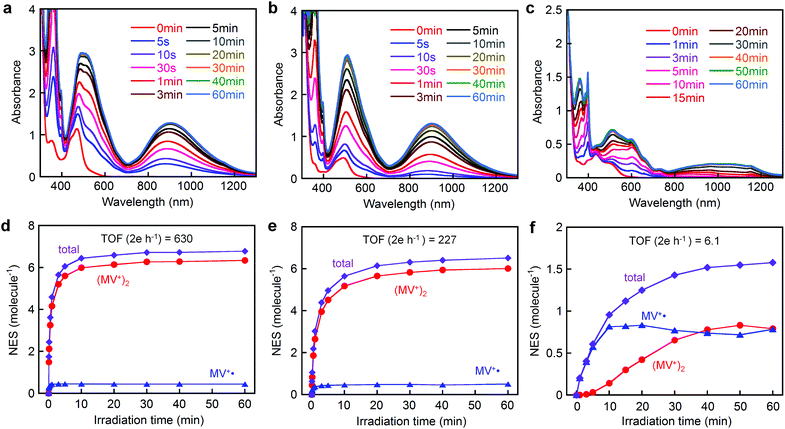
Fig. 5 shows the spectral changes during visible light irradiation (λ > 400 nm) of an aqueous solution (pH 5.0) of either [Ru(4,4′-MV4)3]26+, [Ru(5,5′-MV4)3]26+, or [Ru(bpy)2(5,5′-MV4)]10+ in the presence of EDTA. The two PCSs show new bands in the visible to near infrared region which saturate after 10–20 min, whereas saturation is reached earlier for [Ru(4,4′-MV4)3]26+ in comparison with [Ru(5,5′-MV4)3]26+ (Fig. 5d and e). The Asp-based backbone affords unique positioning of neighboring viologen units, leading to preferential formation of π-dimers (MV+)2, as shown by the major absorptions at 360, 520, and 900 nm in Fig. 5a and b.29,31,33,34 The relative abundances of the MV+˙ and (MV+)2 sites at each irradiation time can be determined by spectral deconvolution (see Fig. 5d–f; see also Fig. S11–S13†). This is one of the two methods employed in this study, and adopts the molar absorptivities of MV+˙ and (MV+)2 reported in the literature (ε548(MV+˙) = 1/2ε548((MV+)2) = 8920 M−1 cm−1).31 The preference for π-dimer formation can be recognized with the apparent dimerization constants (Kd) estimated as (2.57–4.08) × 105 and (1.70–3.42) × 105 M−1 for [Ru(4,4′-MV4)3]26+ and [Ru(5,5′-MV4)3]26+, respectively. These Kd values are significantly larger than those reported for the non-derivatized MV+˙ in aqueous media (Kd = 380–840 M−1).31,35–37 The control experiment carried out for the EDTA/[Ru(bpy)3]2+/MV2+ system under the same conditions (Fig. S9†) re-confirms that π-dimer formation is much less favourable with the Kd value determined as 346–433 M−1 (see Table S9†), in good agreement with the above literature values. On the other hand, such electron charging is extremely hindered for [Ru(bpy)2(5,5′-MV4)]10+ (Fig. 5c and f), for which nearly an hour is required to saturate the electron storage event. Moreover, [Ru(bpy)2(5,5′-MV4)]10+ clearly shows a lower preference to form π-dimers (MV+)2 within the framework (Fig. 5f; Kd = 3.24 × 10²–2.02 × 10⁴ M−1).Based on the results given by the first quantification method described above, the net number of electrons stored per molecule (NES) at saturation is estimated as NES = 6.8 for [Ru(4,4′-MV4)3]26+ and NES = 6.5 for [Ru(5,5′-MV4)3]26+ (Fig. 5d, e and Tables S6 and S7†). Moreover, the TOFs of charge storage can be estimated as 630 2e h−1 for [Ru(4,4′-MV4)3]26+ and 227 2e h−1 for [Ru(5,5′-MV4)3]26+ (Fig. 5d and e), where the TOF (turnover frequency; 2e h−1) is estimated from the initial rate of charge storage and defined as the number of two-electron storage cycles per molecule per hour. These TOFs are clearly higher than that of [Ru(bpy)2(5,5′-MV4)]10+ (TOF = 6.1 2e h−1; Fig. 5f).
On the other hand, slightly higher NES values result from calculations based on the molar absorptivities of the 12-electron-reduced species generated by adding a large excess of sodium dithionite (Na2S2O4);38 NES = 8.2 for both [Ru(4,4′-MV4)3]26+ and [Ru(5,5′-MV4)3]26+ (Fig. S15 and Table S10†). It is well established that the doubly reduced species (i.e., MV0) is not afforded upon addition of Na2S2O4.38 This is the second quantification method adopted. It is thus confirmed that high NES values can be achieved by use of our PCSs. On the basis of NES, our PCSs outperform those reported to demonstrate such multi-electron storage within a unimolecular framework.39–43
Less effective photo-driven multi-electron storage with neutral donor TEOA
The importance of ion-pairing between the highly positively charged PCS and the YH22– anions is evident by the fact that the use of a neutral electron donor, triethanolamine (TEOA), results in a dramatic decrease in both TOF and the maximum NES. Using TEOA, the maximum NES drops to 1.7–1.9 and it takes an hour to reach saturation (Fig. S16†). Due to the steric bulk of viologen tethers, which spherically cover the Ru(bpy)32+ core, the Ru(II)/Ru(III) redox couple exhibits quite low responsiveness to electrode processes (Fig. S17†), in which the electrode current corresponding to the Ru(II)/Ru(III) couple is much lower than expected. These results rationally explain the lower probability of ET to proceed when a donor like TEOA injects an electron to the Ru(III) center without providing sufficient access to the central core corresponding to either RuIII(bpy)33+ (oxidized form) or RuIII(bpy)2(bpy−˙)2+ (3MLCT state). In other words, the ET from YH22– to the Ru(III) center is strongly enhanced by electrostatic interactions. This behavior has a similarity to the recognition adopted when plastocyanin (PC) establishes electrostatic association with PSI prior to transfer of an electron to the oxidized pigment P-700+.44Computational studies
For the two-electron-stored π-dimer (MV+)2, both eclipsed and staggered conformations can be realized as local minimum structures in the DFT calculations performed for the non-derivatized (MV+)2 in a water solvated model (e.g., Fig. 6a). Three possible spin states (closed-shell singlet, open-shell singlet, and triplet) are closely located in energy with the highest energy triplet lying only 1–2 kcal mol−1 higher than the lowest open-shell singlet (Table S12†). For the Asp-based (MV+)2 geometry, staggered rather than eclipsed conformations seem energetically favorable (Table S12† and Fig. 6b). Furthermore, TD-DFT calculations allow us to simulate the spectral features of energy-minimized geometries for all the spin states (Fig. 7). In general, the 900 nm band arises from a HOMO → LUMO transition in both singlet states regardless of the choice of conformation with an exception in Fig. 7b (i.e., a slipped dimer). In other words, the 900 nm transition originates from the weakly bonding orbital established in π-dimers (MV+)2 in a singlet state (see Fig. 7). Notably, the triplet does not absorb in the 900 nm domain and thus can be ruled out, as excluded in the ESR studies (see below). Considering the weakly bonding character of such π-dimers (ca. 10–15 kcal mol−1 (ref. 45)), the two stacked planes are likely to slip between the eclipsed and staggered geometries in solution.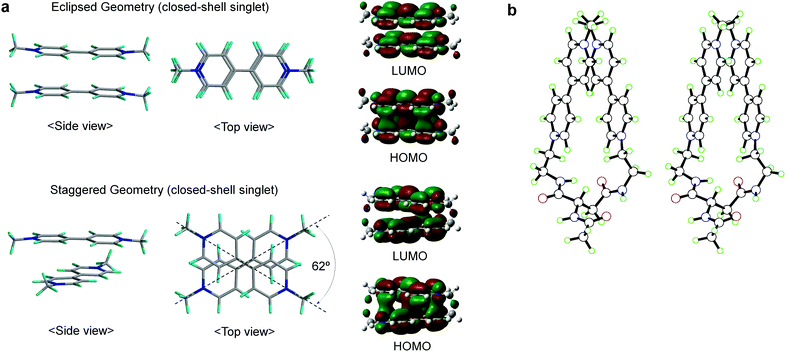 | ||
| Fig. 6 Structures of (MV+)2 computed by DFT. (a) Side and top views of the eclipsed/staggered geometries of non-derivatized (MV+)2 π-dimers in closed-shell singlet states, together with their HOMO/LUMO orbitals correlated with the 900 nm transition, where structures were optimized at the M06 level of DFT using the 6-31G** basis set with solvation in water taken into consideration (PCM). (b) A stereo view for the staggered π-dimer of Asp-based (MV+)2 in an open-shell singlet state, optimized at the UM06/6-31G** level of a broken-symmetry DFT approach with water solvation taken into consideration (PCM). Other details are supplied in the ESI.† | ||
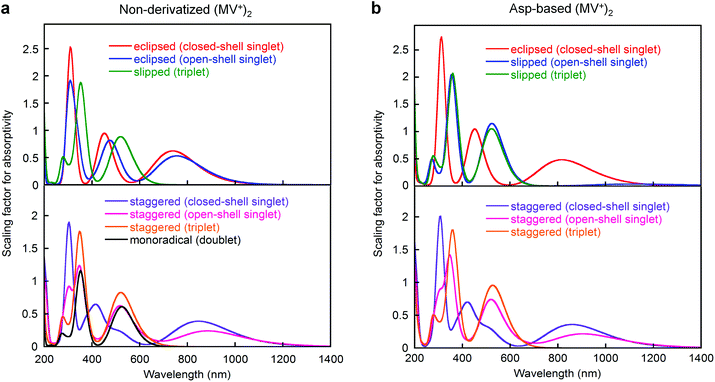 | ||
| Fig. 7 Absorption spectra of (a) non-derivatized and (b) Asp-based (MV+)2 π-dimers computed by DFT, where calculations were performed at either the M06 or UM06 level of DFT using the 6-31G** basis set with solvation in water taken into consideration (PCM). Spectra were simulated using the oscillator strengths of all transitions given in TD-DFT calculations. Other details are supplied in the ESI.† | ||
ESR studies
ESR spectroscopy also evidence the diamagnetic character of the π-dimer (MV+)2, as previously described for some π-dimer analogs.41,46Fig. 8a shows the time course of ESR spectra observed during photoirradiation of the EDTA/[Ru(5,5′-MV4)3]26+ system. A control experiment carried out for the EDTA/[Ru(bpy)3]2+/MV2+ system under the same conditions shows quite similar ESR spectral changes (Fig. 8b and S9a†). In both experiments (Fig. 8a and b), signals attributable to the triplet, previously observed for a crystalline sample of a π-dimer,47 are not observable, and thereby the contribution of such triplet species can be ruled out. In other words, MV+˙ is considered as the only ESR-active species in both of these experiments. The validity of this argument can be confirmed by calibrating the ESR signal intensity (i.e., spin density) using the concentration of MV+˙ separately determined spectrophotometrically. As shown in Fig. 8c, the ESR-intensity vs. time profile shows a good consistency with the MV+˙ concentration vs. time profile calibrated by supposing that both systems involve MV+˙ as the only ESR active species. | ||
| Fig. 8 Detection of ESR-active monoradical (MV+˙) during photo-driven multi-electron storage. ESR spectral changes during photolysis of an aqueous acetate buffer solution (0.1 M, pH = 5.0) containing 30 mM EDTA in the presence of (a) 0.04 mM [Ru(5,5′-MV4)3](PF6)26 or (b) 0.04 mM [Ru(bpy)3](NO3)2 and 2 mM MV(NO3)2 at room temperature under Ar atmosphere, where visible spectral changes observed under the conditions adopted for a and b are shown in Fig. 5b and S9a,† respectively. (c) Intensity-time (i.e., spin-density-time) profiles for a and b are overlaid with the concentration-time profiles of MV+˙ (determined spectrophotometrically). | ||
Light-driven H2 evolution using the PCSs
Finally, we focus on photo-driven water reduction by EDTA promoted by these PCSs, together with [Ru(bpy)2(5,5′-MV4)]10+, by employing PVP-protected colloidal Pt (nanoparticles, 2 nm in diameter; PVP = polyvinylpyrrolidone) as an H2-evolving catalyst. As shown in Fig. 9A, the initial rate of H2 formation promoted by [Ru(4,4′-MV4)3]26+ (TOF = 157 H2 h−1) is clearly higher than that of [Ru(5,5′-MV4)3]26+ (TOF = 47.8 H2 h−1), indicating that the rate of electron charging (TOF 2e h−1 in Fig. 5d–f) rather than the electron storage capacity (i.e., the maximum NES) governs the net rate of H2 evolution (see also Fig. S21†). Furthermore, the rate of H2 evolution is about 70% lower than the rate of electron charging (Fig. S21†), indicating that the overall rate of H2 evolution is limited by the catalytic process. This rate limiting effect can be confirmed by the fact that multi-electron-stored species are observable even in the presence of colloidal Pt under the same conditions (Fig. S22†).When the photo-driven H2 evolution from water is investigated for [Ru(4,4′-MV4)3]26+ and [Ru(bpy)2(5,5′-MV4)]10+ by using TEOA instead of EDTA at the same pH (5.0), photolysis does not cause colour change due to the formation of multi-electron-stored species and no H2 evolves (Fig. S23a and b†). On the other hand, H2 does evolve using a bulk system consisting of TEOA, [Ru(bpy)3]2+, MV2+, and colloidal Pt (Fig. S23c†), indicating that the oxidative quenching path has a major contribution to the MV+˙ formation in the bulk system. These results further strengthen our conclusion that the ion-pair formation of the highly charged PCS with YH22− is essential for the H2 evolution photo-driven by the PCSs.
On the other hand, electron-stored species of PCSs with NES = 1.7–1.9 can be generated using TEOA at pH 7.0 (see above; Fig. S16†). This observation can be rationalized by the enhancement of the second reduction step at this higher pH (i.e., (MV2+)11(MV+˙) + TEOA+˙ → (MV2+)10(MV+)2 + TEOA2+ as a thermal process), as previously reported.32 Nevertheless, when colloidal Pt is added to this TEOA-based system (pH 7.0), H2 does not evolve upon photolysis, which is ascribable to ca. 0.12 eV of loss in the driving force for H2 evolution by raising the pH from 5.0 to 7.0.
In order to clarify the effect of covalent linkages established in the PCSs, a comparison is made between the H2 evolution activities of the PCSs (0.04 mM) and that of a non-hybrid bulk system consisting of 0.04 mM [Ru(bpy)3]2+ and 0.48 mM free MV2+ (12 equiv.), in the presence of both EDTA (30 mM) and colloidal Pt (0.1 mM). As shown in Fig. 9A, under these concentration conditions, the non-hybrid bulk system clearly outperforms the hybrid systems, in which the earlier cease of H2 evolution in the bulk system compared to the PCSs is attributable to the faster degradation of MV2+ by hydrogenation because of the higher H2 concentration in the photolysis solution.48,49 On the other hand, the importance of developing hybrid molecular systems, like these PCSs, may be realized by comparing the photocatalytic performances of the hybrid and non-hybrid systems under the lower-concentration conditions where intermolecular interactions become substantially unfavourable. In other words, even at a lower PCS concentration, it is expected that the above-discussed multi-electron transfer and storage events are still favoured within each PCS framework. With this aim, 40 times dilution was made for the solutions used as shown in Fig. 9A, and their H2 evolution characteristics are similarly measured under the same photolysis conditions. As shown in Fig. 9B, the PCSs now outperform the non-hybrid bulk system. These results support the validity of our approach to develop hybrid molecular systems enabling multi-photon absorption, multi-electron transfer, and multi-electron reduction events within a limited ‘nanospace’ (ca. 5 nm).
Conclusion
Our study thus demonstrates an artificial way of promoting multi-electron flow and storage within a unimolecular architecture on the basis of a single-pigment-driven single-electron-pumping cycle, which can be switched into a π-dimer-mediated double-electron-storage cycle, and can be ultimately coupled with a double-electron-consumption cycle, corresponding to catalytic H2 evolution from water. Our study also points out that enhancement in the rate of photo-driven electron charging is a key to fabricating more highly efficient systems applicable to the practical solar-driven H2 generation. On-going issues involve improvement in the robustness of molecular systems, coupling of hydrogen and oxygen evolving cycles, and coupling of light-harvesting antennas in order to raise fundamental solar energy conversion efficiency. Such studies are still in progress in our laboratory.Experimental section
All the technical details, procedures and sequences are provided in the ESI.†Acknowledgements
This work was supported by a Grant-in-Aid for Scientific Research (B) (no. 24350029), and Grants-in-Aid for Scientific Research on Innovative Areas, ‘Coordination Programming’ (no. 2107) (no. 24108732) and ‘Artificial Photosynthesis’ (no. 2406) (no. 24107004), from the Ministry of Education, Culture, Sports, Science, and Technology (MEXT) of Japan. This was also supported by the International Institute for Carbon Neutral Energy Research (WPI-I2CNER), sponsored by the World Premier International Research Center Initiative (WPI), MEXT, Japan. K.K. acknowledges Research Fellowships of the Japan Society for the Promotion of Science for Young Scientist.Notes and references
- Y. Umena, K. Kawakami, J.-R. Shen and N. Kamiya, Nature, 2011, 473, 55 CrossRef CAS PubMed.
- A. Aliverti, V. Pandini, A. Pennati, M. D. Rosa and G. Zanetti, Arch. Biochem. Biophys., 2008, 474, 283 CrossRef CAS PubMed.
- G. Ananyev and G. C. Dismukes, Photosynth. Res., 2005, 84, 355 CrossRef CAS PubMed.
- N. S. Lewis and D. G. Nocera, Proc. Natl. Acad. Sci. U. S. A., 2006, 103, 15729 CrossRef CAS PubMed.
- M. Kirch, J.-M. Lehn and J.-P. Sauvage, Helv. Chim. Acta, 1979, 62, 1345 CrossRef CAS.
- E. Borgarello, J. Kiwi, E. Pelizzetti, M. Visca and M. Grätzel, Nature, 1981, 289, 158 CrossRef CAS.
- J. H. Alstrum-Acevedo, M. K. Brennaman and T. J. Meyer, Inorg. Chem., 2005, 44, 6802 CrossRef CAS PubMed.
- P. D. Tran, V. Artero and M. Fontcave, Energy Environ. Sci., 2010, 3, 727 CAS.
- M. Wang, L. Chen and L. Sun, Energy Environ. Sci., 2012, 5, 6763 CAS.
- P. Du and R. Eisenberg, Energy Environ. Sci., 2012, 5, 6012 CAS.
- J. R. Swierk and T. E. Mallouk, Chem. Soc. Rev., 2013, 42, 2357 RSC.
- K. J. Young, L. A. Martini, R. L. Milot, R. C. Snoeberger III, V. S. Batista, C. A. Schmuttenmaer, R. H. Crabtree and G. W. Brudvig, Coord. Chem. Rev., 2013, 256, 2503 CrossRef PubMed.
- D. Z. Zee, T. Chantarojsiri, J. R. Long and C. J. Chang, Acc. Chem. Res., 2015, 48, 2027 CrossRef CAS PubMed.
- H. Imahori, D. M. Guldi, K. Tamaki, Y. Yoshida, C. Luo, Y. Sakata and S. Fukuzumi, J. Am. Chem. Soc., 2001, 123, 6617 CrossRef CAS PubMed.
- S. Karlsson, J. Boixel, Y. Pellegrin, E. Blart, H.-C. Becker, F. Odobel and L. Hammarström, J. Am. Chem. Soc., 2010, 132, 17977 CrossRef CAS PubMed.
- A. Juris and V. Balzani, Coord. Chem. Rev., 1988, 84, 85 CrossRef CAS.
- E. Borgarello, J. Kiwi, E. Pelizzetti, M. Visca and M. Grätzel, Nature, 1981, 289, 158 CrossRef CAS.
- K. Sakai and K. Matsumoto, J. Mol. Catal., 1990, 62, 1 CrossRef CAS.
- H. Ozawa, Y. Yokoyama, M. Haga and K. Sakai, Dalton Trans., 2007, 1197 RSC.
- S. Tanaka, S. Masaoka, K. Yamauchi, M. Annaka and K. Sakai, Dalton Trans., 2010, 39, 11218 RSC.
- K. Kawano, K. Yamauchi and K. Sakai, Chem. Commun., 2014, 50, 9872 RSC.
- M. Ogawa, B. Balan, G. Ajayakumar, S. Masaoka, H.-B. Kraatz, M. Muramatsu, S. Ito, Y. Nagasawa, H. Miyasaka and K. Sakai, Dalton Trans., 2010, 39, 4421 RSC.
- S. L. Mecklenburg, B. M. Peek, J. R. Schoonover, D. G. McCafferty, C. G. Wall, B. W. Erickson and T. J. Meyer, J. Am. Chem. Soc., 1993, 115, 5479 CrossRef CAS.
- E. H. Yonemoto, G. B. Saupe, R. H. Schmehl, S. M. Hubig, R. L. Riley, B. L. Iverson and T. E. Mallouk, J. Am. Chem. Soc., 1994, 116, 4786 CrossRef CAS.
- E. Zahavy, M. Seiler, S. Marx-Tibbon, E. Joselevich, I. Willner, H. Dürr, D. O'Connor and A. Harriman, Angew. Chem., Int. Ed. Engl., 1995, 34, 1005 CrossRef CAS.
- L. A. Kelly and M. A. J. Rodgers, J. Phys. Chem., 1995, 99, 13132 CrossRef CAS.
- V. Schild, D. v. Loyen, H. Dürr, H. Bouas-Laurent, C. Turro, M. Worner, M. R. Pokhrel and S. H. Bossmann, J. Phys. Chem. A, 2002, 106, 9149 CrossRef CAS.
- P. K.-L. Fu, P. M. Bradley, D. v. Loyen, H. Dürr, S. H. Bossmann and C. Turro, Inorg. Chem., 2002, 41, 3808 CrossRef CAS PubMed.
- M. Ogawa, G. Ajayakumar, S. Masaoka, H.-B. Kraatz and K. Sakai, Chem. – Eur. J., 2011, 17, 1148 CrossRef CAS PubMed.
- C. V. Suneesh, B. Balan, H. Ozawa, Y. Nakamura, T. Katayama, M. Muramatsu, Y. Nagasawa, H. Miyasaka and K. Sakai, Phys. Chem. Chem. Phys., 2014, 16, 1607 RSC.
- J. W. Park, N. H. Choi and J. H. Kim, J. Phys. Chem., 1996, 100, 769 CrossRef CAS.
- K. Kalyanasundaram, J. Kiwi and M. Grätzel, Helv. Chim. Acta, 1978, 61, 2720 CrossRef CAS.
- K. Kitamoto and K. Sakai, Angew. Chem., Int. Ed., 2014, 53, 4618 CrossRef CAS PubMed.
- C. Lee, Y. M. Lee, M. S. Moon, S. H. Park, J. W. Park, K. G. Kim and S.-J. Jeon, J. Electroanal. Chem., 1996, 416, 139 CrossRef CAS.
- J. F. Stargardt and F. M. Hawkridge, Anal. Chim. Acta, 1983, 146, l CrossRef.
- J. G. Gaudiello, P. K. Ghosh and A. J. Bard, J. Am. Chem. Soc., 1985, 107, 3027 CrossRef CAS.
- C. Lee, C. Kim, M. S. Moon and J. W. Park, Bull. Korean Chem. Soc., 1994, 15, 909 CAS.
- S. G. Mayhew, Eur. J. Biochem., 1978, 85, 535 CrossRef CAS PubMed.
- R. Konduri, H. Ye, F. M. MacDonnell, S. Serroni, S. Campagna and K. Rajeshwar, Angew. Chem., Int. Ed., 2002, 41, 3185 CrossRef CAS.
- B. Matt, J. Fize, J. Moussa, H. Amouri, A. Pereira, V. Artero, G. Izzet and A. Proust, Energy Environ. Sci., 2013, 6, 1504 CAS.
- J. M. Spruell, A. Coskun, D. C. Friedman, R. S. Forgan, A. A. Sarjeant, A. Trabolsi, A. C. Fahrenbach, G. Barin, W. F. Paxton, S. K. Dey, M. A. Olson, D. Benítez, E. Tkatchouk, M. T. Colvin, R. Carmielli, S. T. Caldwell, G. M. Rosair, S. G. Hewage, F. Duclairoir, J. L. Seymour, A. M. Z. Slawin, W. A. Goddard III, M. R. Wasielewski, G. Cooke and J. F. Stoddart, Nat. Chem., 2010, 2, 870 CrossRef CAS PubMed.
- J. Iehl, M. Frasconi, H.-P. Jacquot de Rouville, N. Renaud, S. M. Dyar, N. L. Strutt, R. Carmieli, M. R. Wasielewski, M. A. Ratner, J.-F. Nierengartenc and J. F. Stoddart, Chem. Sci., 2013, 4, 1462 RSC.
- H. Li, A. C. Fahrenbach, A. Coskun, Z. Zhu, G. Barin, Y. L. Zhao, Y. Y. Botros, J.-P. Sauvage and J. F. Stoddart, Angew. Chem., Int. Ed., 2011, 50, 6782 CrossRef CAS PubMed.
- G. P. Anderson, D. G. Sanderson, C. H. Lee, S. Durell, L. B. Anderson and E. L. Gross, Biochim. Biophys. Acta, 1987, 894, 386 CrossRef CAS.
- F. Mota, J. S. Miller and J. J. Novoa, J. Am. Chem. Soc., 2009, 131, 7699 CrossRef CAS PubMed.
- A. T. Buck, J. T. Paletta, S. A. Khindurangala, C. L. Beck and A. H. Winter, J. Am. Chem. Soc., 2013, 135, 10594 CrossRef CAS PubMed.
- C. Femoni, M. C. Iapalucci, G. Longoni, C. Tiozzo, J. Wolowska, S. Zacchini and E. Zazzaroni, Chem. – Eur. J., 2007, 13, 6544 CrossRef CAS PubMed.
- P. Keller, A. Moradpour, E. Amouyal and H. B. Kagan, Nouv. J. Chim., 1980, 4, 377 CAS.
- K. Sakai, Y. Kizaki, T. Tsubomura and K. Matsumoto, J. Mol. Catal., 1993, 79, 141 CrossRef CAS.
Footnotes |
| † Electronic supplementary information (ESI) available. See DOI: 10.1039/c5qi00150a |
| ‡ Current address: Catalysts Division, Engineered Materials Sector, Mitsui Mining & Smelting Co., Ltd, 1013-1, Ageoshimo, Ageo, Saitama 362-0025, Japan. |
| § Current address: Department of Chemistry, Government College for Women, Vazhuthacaud, Thycaud P O, Thiruvananthapuram, Kerala 695014, India. |
| ¶ Current address: Institute for Molecular Science, Higashiyama 5-1, Myodaiji, Okazaki 444-8787, Japan. |
| This journal is © the Partner Organisations 2016 |

