 Open Access Article
Creative Commons Attribution 3.0 Unported Licence
Mechanical properties and current-carrying capacity of Al reinforced with graphene/BN nanoribbons: a computational study
D. G.
Kvashnin
 ab,
M.
Ghorbani-Asl
c,
D. V.
Shtansky
a,
D.
Golberg
de,
A. V.
Krasheninnikov
cf and
P. B.
Sorokin
*agh
aNational University of Science and Technology MISiS, Leninskiy prospect 4, Moscow, 119049, Russian Federation. E-mail: pbsorokin@misis.ru
bEmanuel Institute of Biochemical Physics RAS, 4 Kosigina st., Moscow, 119334, Russian Federation
cInstitute of Ion Beam Physics and Materials Research, Helmholtz-Zentrum Dresden-Rossendorf, 01314 Dresden, Germany
dInternational Center for Materials Nanoarchitectonics (MANA), National Institute for Materials Science (NIMS), Namiki 1-1, Tsukuba, Ibaraki 3050044, Japan
eGraduate School of Pure and Applied Sciences, Tennodai 1, University of Tsukuba, Tsukuba, Ibaraki 3058577, Japan
fDepartment of Applied Physics, Aalto University, P.O. Box 11100, FI-00076 Aalto, Finland
gMoscow Institute of Physics and Technology, 141700, 9 Institutsky lane, Dolgoprudny, Russian Federation
hTechnological Institute for Superhard and Novel Carbon Materials, 7a Centralnaya Street, Troitsk, Moscow, 142190, Russian Federation
First published on 14th November 2016
Abstract
Record high values of Young's modulus and tensile strength of graphene and BN nanoribbons as well as their chemically active edges make them promising candidates for serving as fillers in metal-based composite materials. Herein, using ab initio and analytical potential calculations we carry out a systematic study of the mechanical properties of nanocomposites constructed by reinforcing an Al matrix with BN and graphene nanoribbons. We consider a simple case of uniform distribution of nanoribbons in an Al matrix under the assumption that such configuration will lead to the maximum enhancement of mechanical characteristics. We estimate the bonding energy and the interfacial critical shear stress at the ribbon/metal interface as functions of ribbon width and show that the introduction of nanoribbons into the metal leads to a substantial increase in the mechanical characteristics of the composite material, as strong covalent bonding between the ribbon edges and Al matrix provides efficient load transfer from the metal to the ribbons. Using the obtained data, we apply the rule of mixtures in order to analytically assess the relationship between the composite strength and concentration of nanoribbons. Finally, we study carbon chains, which can be referred to as the ultimately narrow ribbons, and find that they are not the best fillers due to their weak interaction with the Al matrix. Simulations of the electronic transport properties of the composites with graphene nanoribbons and carbyne chains embedded into Al show that the inclusion of the C phase gives rise to deterioration in the current carrying capacity of the material, but the drop is relatively small, so that the composite material can still transmit current well, if required.
Introduction
Lightweight and mechanically strong materials are of high importance in modern automotive and especially the aerospace industry where even a small reduction of craft weight can give rise to a considerable drop in the operation costs. Nowadays the materials used in this area are mostly based on aluminum, which is a reasonable compromise between the weight, cost and mechanical characteristics, which are in fact far from being impressive for pure Al: its Young's modulus is about 70 GPa, and tensile strength is 40 MPa only.1 The improvement of the mechanical characteristics of Al-based alloys and composites can not only lead to enhanced performance of the present day machines, but can also give access to principally new technologies in automotive, aviation and aerospace industries. Furthermore, metal–carbon composites have been considered to be promising materials to replace conventional conductors due to lower cost, lower density and corrosion renitent character.Relatively modest mechanical characteristics of Al can potentially be increased by an Al matrix with stiff and elastic materials, e.g., with carbon or boron nitride nanostructures, which have high elastic constants, excellent elasticity and a low equilibrium concentration of defects due to their high formation energies.2 This idea has been explored in a number of papers3–6 where carbon and BN nanotube-based Al composites were investigated. It was found that only 3 wt% of BN nanotubes increases tensile strength at room temperature up to 350 MPa,7 which is comparable to the strength of some structural steels, but the Al-based material was nearly three times lighter. However, in spite of considerable improvements of the mechanical characteristics of the composite as compared to the pure metal, it was found that low adhesion of the nanotube surface to metal does not allow reaching the theoretical upper limit of mechanical rigidity.
The problem of low adhesion originates from the inertness of the nanotube surface. A solution was proposed, which assumed intentional introduction of point defects6,8 or molecular links between the nanotube and the matrix.4 However, this approach, especially when defects are involved, leads to a decrease in the elastic stiffness of the filler.
In the recent experimental reports on using a powder metallurgy method for fabrication and investigation of aluminum matrix composites reinforced with graphene nanoplatelets (few layer graphene sheets), an increase in the ultimate tensile strain up to 46% after inclusion of 0.25 wt% graphene nanoplatelets was demonstrated.9 This phenomenon was also confirmed by DFT calculations.10 Graphene multi-layered nanosheets are widely used for the reinforcement of ceramic matrices. For example, increasing of the fracture toughness (up to 53%) of Al2O3 after embedment of 2 wt% graphene nanosheets was observed.11 In addition, the inclusion of 1.5 vol% of graphene platelets into a Si3N4 matrix led to the enhancement of fracture toughness up to 136%.12
Very recent experiments13 indicate that graphene flakes can be uniformly distributed in the Al matrix by cooling the metal from the melt, and that the hardness, strength and ductility of aluminum–graphene composites are at least 2–3 times higher than in the initial aluminum material, proportional to the concentration of graphene, which is about 2%. Graphene has excellent mechanical characteristics, but it is also chemically inert. Therefore, it is desirable to find other nanomaterials with comparable mechanical characteristics, but with more reactive surfaces, or optimize the geometry of graphene flakes. From such point of view graphene and BN nanoribbons (GNR and BNNR, respectively), in one-dimensional (1D) systems, can be considered as a good choice. The Young's modulus of such nanostructures (normalized over ribbon width) is comparable to that of nanotubes and even increases with decreasing the ribbon width,14 whereas reactive ribbon edges can strongly bind to the metal matrix.
Pristine nanoribbons with high mechanical stiffness are expected to strongly increase the mechanical characteristics of a whole Al-based composite. As the ultimately thin ribbon, carbyne, that is the chain of C atoms, can be considered. The theoretically predicted high Young's modulus (1.34–1.75 TPa, ref. 15) and large accessible surface area make carbyne promising in such kind of applications, but the value of binding with a matrix should be estimated and the behavior of carbyne in the matrix under tension should be studied in detail. The same is, in fact, true for nanoribbons, as the mechanical characteristics of ribbons embedded into an Al matrix may be different from those for free-standing systems.
Herein we use atomistic simulations at density functional theory (DFT) and analytical potential levels to carry out a systematic fundamental study on the interfacial mechanical properties of the nanocomposites based on Al strengthened by BN/graphene nanoribbons and their dependence on the nanoribbon widths. The obtained data allows us to construct the analytical model of composite strength changes upon the concentration of nanoribbons using the well-known rule of mixtures.16,17 The concentration of nanoribbons was taken from 6 wt% to 13 wt% as a compromise between the computational costs and the typical (normally smaller) experimental values.7,18 Our results indicate that the presence of the non-passivated edges strongly improves nanocomposite mechanical characteristics. We further show that the decrease in the nanoribbon width leads to the increase in the interaction with the Al matrix. We also investigate the interaction of carbyne with the Al matrix and assess the mechanical characteristics of such material. Finally, keeping in mind the possible simultaneous use of the composites for reinforcement and electrical applications, we study the electronic transport in the composite material.
Computational details
All calculations of the atomic structure, interaction at the interfaces between graphene/BN and Al, as well as the mechanical properties of the BNNR(GNR)/Al composite were performed using the DFT and PAW formalism19 as implemented in the Vienna Ab initio Simulation Package.20,21 The exchange and correlation functional included a nonlocal van der Waals (vdW) component.22,23 The plane-wave energy cutoff was equal to 450 eV. To calculate the equilibrium atomic structures, the Brillouin zone was sampled according to the Monkhorst–Pack scheme with a grid 8 × 1 × 1 k-point. The structural relaxation was performed until the forces acting on each atom were less 0.001 eV Å−1. The width of the embedded nanoribbons varied from 0.4 nm to 2.3 nm. The models of the nanoribbon–Al composites consisted of up to 105 aluminum atoms and 38 atoms in the ribbon. Rectangle supercells were used. Test calculations showed that the interaction between the embedded nanoribbons and Al matrix depends on the distance between the periodic images of the ribbon (that is how many layers of Al are between them), but after five Al layers the changes in the binding energy are negligible (less than 0.7 meV Å−2).We estimated the binding energy of the filler in the matrix as Etotb = E[A + B] − E[A] − E[B], where E[A + B] is the total energy of the whole structure, and E[A] and E[B] are energies of the constituent parts A (Al matrix) and B (nanoribbons, carbyne) calculated in the same supercell.
We also assessed critical shear stress as one of the most important parameters in macroscopic models of composite materials, such as nanotube–metal4 and nanotube–polymer composites16,24 or nanotube networks.24 The shear stress was calculated by moving the nanoribbon stepwise along the periodic axis. For each step the geometry optimization and total energy calculations were performed. Then the critical shear stress, τc, was defined as the maximum force along the moving direction divided by the surface area. We assumed that during the sample preparation the nanoribbons were distributed uniformly and isotropically in the metal matrix, which would lead to the isotropic improvement of the composite mechanical characteristics, and the response of the macroscopic sample to mechanical deformation is governed by the behavior of the fillers under tensile strain, not their bending.
To better understand the behavior of carbyne–Al composites under the mechanical load, we also carried out analytical potential molecular dynamics simulations using the LAMMPS package.25 An empirical potential of Baskes26 was used to describe the interaction between Al atoms, and a pair potential for C–Al was introduced and parameterized based on the DFT results, as detailed below.
The coherent transport calculations were performed using the Atomistix ToolKit (ATK) code.27 The calculations were done using the GGA/PBE functional28 with SIESTA-type numerical basis sets. We used an energy cutoff of 150 Ry and 0.0002 Ry of tolerance for the self-consistent calculations. The direction perpendicular to the transport axis was assumed to be infinite by applying periodic boundary conditions. The Brillouin zone of the transport model was sampled with 5 × 5 × 100 k-points. The Poisson–Schrödinger equation of the system was self-consistently solved using a Fast Fourier Transform (FFT) solver.
The electrical current through the device under non-equilibrium conditions, i.e. for a finite bias voltage (VBias), can be calculated using the Landauer formula:
 represents the chemical potentials of the left and right electrodes, and T(ε,VBias) is the energy and voltage-resolved transmission function.
Results and discussion
We started the analysis by studying the properties of graphene and BN nanoribbons in the Al matrix. We focused on the simple case of the orientation of the nanostructures along the <100> direction of the Al crystal. In Fig. 1a, the atomic structure of an armchair GNR with a width of 9 graphene unit vectors embedded into the Al matrix is presented. Herein we considered the simple case of uniformly distributed nanoribbons embedded into ideal rectangular holes of an Al matrix under the assumption that such distribution and ideal interface between aluminum and nanoribbons will lead to the maximum enhancement of mechanical characteristics. The mechanical characteristics of an Al-based nanocomposite with randomly distributed nanoribbons were expected to lead to the properties not better than those considered below.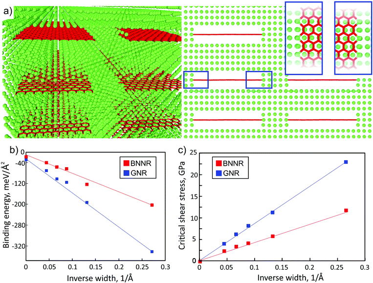 | ||
| Fig. 1 Atomic structure of an armchair GNR/Al composite (a): perspective (left), front (right) and top (inset, blue frames) view; aluminum and carbon atoms are depicted by green and red colors, respectively. Dependences of the binding energy (b) and critical shear stress (c) of graphene (blue dots) and BN (red dots) nanoribbons on the ribbon inverse width. The values of binding energy vary from −40.77 meV Å−2 (−70.47 meV Å−2) for 19-BNNR (19-GNR) to −203.64 meV Å−2 (−333.93 meV Å−2) for 4-BNNR (4-GNR). The value of binding energy is much larger than that for nanocomposites based on the h-BN sheet and metal matrix (Al: −14 meV Å−2,6 Mg: from −9 to −16 meV Å−2 depending on the orientation of the metal surface8). For wide ribbons, the binding energy of the ribbons approaches that for h-BN/graphene sheets as the relative contribution of the edges decreases, see (b). The binding of the Al matrix with GNR (blue dots) is approximately two times higher than that with BN based nanoribbons (red dots) with the same width. | ||
We found that the binding energy between Al and BNNR/GNR (normalized per ribbon area), which included bonding at the edges and vdW interaction, strongly increased (the absolute value) when the nanoribbon became narrower.
Assuming that the obtained dependence of the normalized binding energy on the inverse nanoribbons width W can be described in terms of energy contributions from the vdW (between Al and nanoribbon surfaces, Esurf) and covalent (between the Al matrix and NR edges, Eedge) interactions, it can be written as:
For each width of the nanoribbon we also estimated critical shear stress τc, which is one of the most important mechanical characteristics of the composite (Fig. 1c). It was calculated from energy-nanoribbon displacement dependence. It was found that in the case of nanoribbons embedded into the Al matrix critical shear stress reaches values up to 11 GPa and 20 GPa for BNNR and GNR, respectively. These values are significantly larger than those for h-BN/Al6 or Mg/h-BN/Mg8 interfaces, both pristine (∼101 MPa) and with defects (∼102–103 MPa).
The decrease in the nanoribbon width leads not only to the increase of binding energy, but also to the increase of critical shear stress. In a similar way, we can assume that the contribution to the critical shear stress originates from vdW (between Al and NR surfaces, τsurfc) and covalent (between the Al matrix and NR edges, τedgec) interactions, so that
The calculated values of τsurfc and τedgec are 28 MPa (24.4 MPa) and 22.53 GPa (45.23 GPa) for BNNR (GNR), respectively. The values (as in the case of discussion about binding energy) indicate that whereas h-BN/graphene of infinite lateral size displays apparently low tensile strength at the interface, the presence of edges increases significantly the critical shear stress value thus allowing mechanical reinforcement of the composite by nanoribbons.
We can estimate the elastic rigidity of the nanocomposite by calculating the elastic constant C through:
| CA+B = (1 − α)CA + αCB | (1) |
At first, we calculated elastic constants of the single nanoribbons considered in this work. Our data agreed well with the reference results of elastic constants of both graphene and BN nanoribbons.14,29–31 In the case of armchair nanoribbons only a weak dependence of the elastic constant on ribbon width was observed, while the dependence of the elastic constant on the width of zigzag nanoribbons was much stronger. As only armchair nanoribbons were used here for the calculation of elastic constants through eqn (1), the reference values of C were taken from our ab initio calculations as C11 of graphene and h-BN, which were 1015.82 GPa and 733.29 GPa, respectively. Also the elastic constant of the pure bulk Al was calculated, and the obtained value 103.8 GPa was in a good agreement with the reference result.32
We compared the elastic constants of Al-based composites yielded from direct ab initio calculations and estimates through eqn (1), see Fig. 2 (filled dots and lines, respectively). The variable α of the embedded compound B (C atoms) in the considered supercell was defined as the volume which nanoribbon occupy in bulk Al, and it was obtained from the designed atomistic model and was varied from 0.12 vol% to 0.22 vol%. We defined the ratio in terms of the area due to the fact that during the simulation in considered composite materials only two lattice parameters were changed and the lattice parameter along the periodic direction of nanoribbons remained the same at each of composite materials. Elastic constants of the Al composite depend on the concentration of embedded nanoribbons, which means that with increasing the nanoribbon concentration the elastic constants will tend to match the values of pristine nanoribbons.
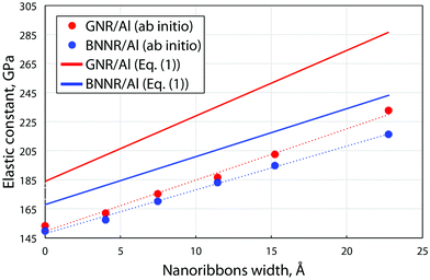 | ||
| Fig. 2 Dependence of the ab initio calculated (filled circles) and estimated from eqn (1) (solid lines) uniaxial elastic constant C of the BN/graphene nanoribbons/Al-composite on the width of the ribbons embedded into Al. The data for graphene and BN nanoribbons are depicted by red and blue color, respectively. By zero width the values of the elastic constant of monoatomic BN/carbon chains are presented. | ||
We found that dependencies of both GNR/Al and BNNR/Al composite elastic constants on the ribbon width fit the linear trend in which slopes correspond well with the rule of mixtures. We observed that the introduction of the ribbons into Al leads to sufficient stiffening of the material, no less than 50%. Eqn (1) overestimates the elastic constant values (by ∼30% for GNR/Al and by ∼15% for BNNR/Al) mainly due to the surface effects, which cannot be described by a simple relation. Nevertheless the similarity between the two sets of data allows us to conclude that the rule of mixtures can be used for the estimation of the composite rigidity.
This result and binding energy values unambiguously indicate that the introduction of nanoribbons with chemically active edges to the metal matrix can produce material with superior mechanical properties (the highest value of τc). On the other hand, the increasing of the nanoribbon width leads to the decreasing of the connection strength between the composite parts (Fig. 1b) with following decreasing of τc (Fig. 1c) which requires fine tuning of the balance between composite rigidity and binding.
It is also interesting to investigate the limiting case of the smallest possible ribbon with a width of just a single atom, which is an atomic chain. We note here that even though carbon33,34 and BN35 chains were recently produced and directly imaged using transmission electron microscopes, they can hardly be manufactured in substantial quantities and stabilized inside an Al matrix. However, carbon interstitial atoms implanted in Al may form such line defects. From the naive point of view, the absence of ‘inner atoms’ in the filler should lead to stronger binding, and therefore chains could be the best possible fillers for the composite, especially given that carbon atomic chains or carbyne are expected to have the highest values of Young's modulus, ranging from 1.34 TPa for polyyne and 1.75 TPa for cumulene phases.15 The values of Young's modulus for carbyne (in the polyyne phase) and BN chains we proved to be 1.38 GPa and 1.19 GPa, respectively. At the same time, the interaction with the matrix can reduce Young's modulus of the chain, as some electron density will be redistributed from covalent bonds between the atoms to the matrix–chain bonds or the other way round, and hence the interaction of the chain with the matrix may be too weak for substantial load transfer.
Our simulations show that atomic chains are worse fillers than GNRs. We first studied the stability of the carbon chain in Al. We calculated the difference in energy between carbyne in the metal and separated carbon atoms in the same metal supercell with the same number of absent Al atoms. We found that the energy gain in the case of formation of carbyne is 1.23 eV per C atom which suggests that carbon chains in Al might form due to coalescence of C atoms in Al with vacancies. Our calculations show that the polyyne configuration is more stable than cumulene in agreement with the previous results.36,37 Like in the case of pure carbyne, the carbyne/Al composite also displays the polyyne configuration of carbyne embedded into the Al matrix. Since the simulation setup the supercell contains the same number of Al layers in the matrix as in the ribbons case, the rule of mixtures predicts the value of 180.8 GPa and 169.9 GPa for carbyne and the BN chain, respectively (Fig. 2). However DFT calculation yields lower elastic moduli of 153.5 GPa and 149.7 GPa, respectively, so that the increase in the stiffness with regard to pure Al is about ∼50%. The calculated elastic constants for Al with chains are presented in Fig. 2 as those for nanoribbons of zero width. Such a relatively low value is originated from the bonding in C chains, in particular, in carbyne the atoms are connected by the σ bond with two additional unpaired π orbitals which are responsible for the weak interface interaction with Al. This leads to low values of critical shear stress of carbyne and BN chains embedded in the Al matrix, which are 2.89 GPa and 0.69 GPa, respectively, whereas in the case of the nanoribbon based Al-composite an order of magnitude larger values were obtained, as discussed above.
Despite modest mechanical characteristics, carbyne is the useful model filler for the study of the process of composite deformation. In order to gain insight into the mechanism of hardening of Al composites and to better understand its behavior under strain, analytical potential molecular dynamics simulations were carried out. For the description of the carbyne interaction with metal the 6–9 potential  was used.
Such pair potentials can be applied for the description of the interaction between carbyne and Al due to the uniform distribution of the π orbitals of cylindrical symmetry along the chain37 responsible for bonding with surrounded Al. Such a simple pair potential can be easily parameterized using DFT data. We fitted the potential only to the case of shifting carbyne in the <100> direction and only this direction was studied further. The interaction parameters were fitted as: ε = 141 eV, σ = 2.32 Å, the potential with these parameters predicted the value of the critical shear stress of the carbyne chain embedded in the Al matrix as 2.29 GPa with respect to 2.89 GPa obtained from DFT.
The composite was represented by a finite slab consisting of ∼55 × 103 Al atoms with embedded 70 C atoms in the carbyne chain. Mixed boundary conditions were used with the mechanical stress being applied along the nonperiodical direction. During the simulations, one Al atomic layer on the slab surfaces was kept fixed, whereas the Al layer of the slab on the opposite side was moved along the carbyne axis with a step of 0.06 Å.
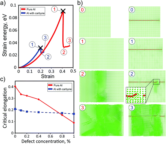
Fig. 3a shows the dependences of the strain energy of pure Al and the Al matrix with the carbyne chain (concentration of about 0.12%). It is evident that the presence of the carbyne embedded in the Al matrix leads to a decrease in the critical stress value from ∼40% to ∼20% (step 3 of the red and blue curves, respectively). In spite of larger values of strain energy at small strain values (which means that the carbyne/Al-composite is stiffer) the breaking point of the composite is smaller than that of the pure Al case. This result can be explained by the absence of a large number of Al atoms in the tunnel where the chain is located, which facilitates the breaking process. During the elongation the length of the structure monotonically increases up to the breaking point when carbyne breaks and the whole structure is fractured (Fig. 3b, step 3). Under the strain, carbyne undertakes the applied load and prevents the composite from breaking. This result additionally validates the critical importance of critical shear stress in the description of nanocomposite mechanical characteristics. Such behavior of the composite is manifested in the dependence of the elastic energy (Fig. 3a) on strain. We stress that the values of critical stress correspond to perfect crystals, and the actual values should be lower.
Additionally, the investigation of the dependence of the carbyne based Al-composite under strain on the defect concentration was carried out. Only Al monovacancy defects were considered. The increase in the concentration of vacancies leads to the decrease in the critical elongation values for both cases, but the slope of the pure Al dependence is much larger, see Fig. 3c. Both the dependencies cross at a defect concentration of ∼0.8%, and after this value the critical elongation becomes larger for the carbyne based Al-composite than for pure Al.
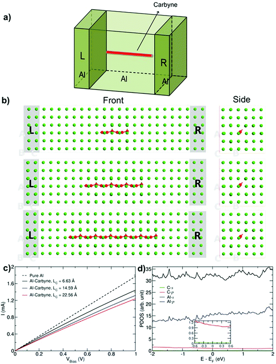
Finally, we studied the transport properties of carbon–Al composites with various graphene ribbons and carbyne chains. The setup for transport calculations for an example of carbyne (Fig. 4) consists of Al with carbyne (of length Lc) as a channel region and two semi-infinite perfect aluminum electrodes (L and R). In order to eliminate artificial effects from the coupling, a small part of the electrodes is included in the channel region as buffer layers. Here we assume that the direction of the GNR and chains is along the transport direction, which has been found to be the most favorable orientation for the metal–carbon composites.38
Fig. 4c presents the current–voltage characteristics of the Al–carbyne composite with three different lengths, Lc. The characteristic of infinite pure Al is also shown for comparison. The results show that with increasing the length of the chain, the current gradually decreases. The effect can be related to the dominant contribution of Al-p orbitals in the electronic structure close to the Fermi level, while C atoms have no significant impact as it is shown in PDOS (see Fig. 4d). As a result by decreasing the number of aluminum atoms in the system, electron density decreases which reduces the current.
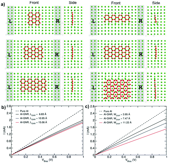
Fig. 5a shows the current–voltage characteristics for Al–GNR composites with different lengths and widths. Similarly to the Al–carbyne composite, the inclusion of C chains decreases the transport characteristics of Al, but the drop is larger in the case of length variation in comparison to width variation due to a higher proportion in the volume fraction of the C phase.
Furthermore, the differential conductance  of the Al–GNR composite was examined as a function of overall mass density (ρ) of the composite (Fig. 6). As expected, the conductance increases with mass density. Using a linear fitting, we can find an equation that correlates the transport properties with the density of the composite. For instance, an increasing density by ∼17% can enhance conductivity by 37%.
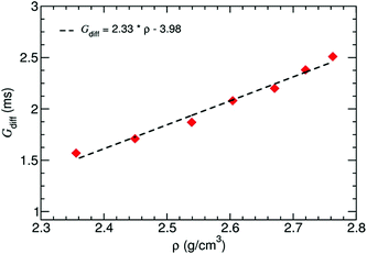 | ||
| Fig. 6 Differential conductance of the Al–GNR composite as a function of the overall mass density of the composite. | ||
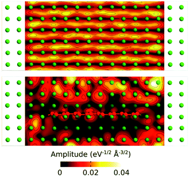
We have further analyzed the transport mechanism through the composite by calculating the transmission eigenstates via the diagonalization of the transmission matrix (Fig. 7). The results show that the transmission modes in the composite change dramatically by embedding the GNR into the Al matrix.
In the pure Al the amplitudes of the transmission keep similar values through the whole structure, while in the composite the values are significantly reduced on the areas around the GNR. This can be related to the scattering occurring at the Al/GNR interface that can be responsible for the reduction in transmission through the composite.38
Conclusions
We theoretically studied the possibility of using graphene and h-BN nanoribbons for the reinforcement of Al. We found that contrary to carbon and BN nanotubes the active chemical edges of the ribbons create strong chemical bonding between the filler and metal matrix and yield critical shear stress in the GPa range. This result combined with the enhanced rigidity of narrow nanoribbons indicates that such nanoribbons can be considered as prospective fillers in the metal composite. However, carbon chains, which can be referred to as the ultimately narrow ribbons, are not the best fillers due to their weak interaction with the Al matrix. The investigation of the electronic transport properties of the carbyne based Al-composite showed that the inclusion of the C phase gives rise to deterioration in the current carrying capacity of the material due to free electron density lowering and scattering at the interface. However, the ratio of the reduction in conductance is lower than the overall gain in composite density. Thus our results could be used for the design and fabrication of novel Al-based composites with optimal mechanical and electrical properties.Acknowledgements
The work was supported by the Ministry of Education and Science of the Russian Federation (Increase Competitiveness Program of NUST “MISiS” no. K2-2015-067). P. B. S. acknowledges the Grant of President of Russian Federation for government support of young PhD scientists (MK-6218.2015.2) and Government Task, project #3556. A. V. K. acknowledges the Academy of Finland funding through project 286279. We thank the CSC IT Center for Science Ltd, Finland, for generous grants of computer time. Authors are also grateful to the ‘Chebyshev’ and ‘Lomonosov’ supercomputers of the Moscow State University for the possibility of using a cluster computer for our quantum-chemical calculations.Notes and references
- T. Y. Tsui, W. C. Oliver and G. M. Pharr, J. Mater. Res., 1996, 11, 752–759 CrossRef CAS.
- F. Banhart, J. Kotakoski and A. V. Krasheninnikov, ACS Nano, 2011, 5, 26–41 CrossRef CAS PubMed.
- T. Laha, A. Agarwal, T. McKechnie and S. Seal, Mater. Sci. Eng., A, 2004, 381, 249–258 CrossRef.
- S. R. Bakshi, D. Lahiri and A. Agarwal, Int. Mater. Rev., 2010, 55, 41–64 CrossRef CAS.
- D. Golberg, Y. Bando, Y. Huang, T. Terao, M. Mitome, C. Tang and C. Zhi, ACS Nano, 2010, 4, 2979–2993 CrossRef CAS PubMed.
- A. V. Krasheninnikov, N. Berseneva, D. G. Kvashnin, J. Enkovaara, T. Björkman, P. Sorokin, D. Shtansky, R. M. Nieminen and D. Golberg, J. Phys. Chem. C, 2014, 118, 26894–26901 CAS.
- M. Yamaguchi, A. Pakdel, C. Zhi, Y. Bando, D.-M. Tang, K. Faerstein, D. Shtansky and D. Golberg, Nanoscale Res. Lett., 2013, 8, 3–8 CrossRef PubMed.
- D. G. Kvashnin, A. V. Krasheninnikov, D. Shtansky, P. B. Sorokin and D. Golberg, Phys. Chem. Chem. Phys., 2015, 18, 965–969 RSC.
- M. Rashad, F. Pan, Z. Yu, M. Asif, H. Lin and R. Pan, Prog. Nat. Sci.: Mater. Int., 2015, 25, 460–470 CrossRef CAS.
- S. E. Shin, H. J. Choi, J. Y. Hwang and D. H. Bae, Sci. Rep., 2015, 5, 16114 CrossRef CAS PubMed.
- K. Wang, Y. Wang, Z. Fan, J. Yan and T. Wei, Mater. Res. Bull., 2011, 46, 315–318 CrossRef CAS.
- L. S. Walker, V. R. Marotto, M. A. Rafiee, N. Koratkar and E. L. Corral, ACS Nano, 2011, 5, 3182–3190 CrossRef CAS PubMed.
- L. A. Yolshina, R. V. Muradymov, I. V. Korsun, G. A. Yakovlev and S. V. Smirnov, J. Alloys Compd., 2016, 663, 449–459 CrossRef CAS.
- R. Faccio, P. A. Denis, H. Pardo, C. Goyenola and Á. W. Mombrú, J. Phys.: Condens. Matter, 2009, 21, 285304 CrossRef PubMed.
- X. Liu, G. Zhang and Y.-W. Zhang, J. Phys. Chem. C, 2015, 119, 24156–24164 CAS.
- J. N. Coleman, U. Khan, W. J. Blau and Y. K. Gun'ko, Carbon, 2006, 44, 1624–1652 CrossRef CAS.
- Materials Science and Engineering: An Introduction, ed. W. D. Callister and D. G. Rethwisch, Wiley, 9th edn, 2014, pp. 637–641 Search PubMed.
- D. Lahiri, A. Hadjikhani, C. Zhang, T. Xing, L. H. Li, Y. Chen and A. Agarwal, Mater. Sci. Eng., A, 2013, 574, 149–156 CrossRef CAS.
- P. E. Blöchl, Phys. Rev. B: Condens. Matter, 1994, 50, 17953–17979 CrossRef.
- G. Kresse and J. Furthmüller, Comput. Mater. Sci., 1996, 6, 15–50 CrossRef CAS.
- G. Kresse and J. Furthmüller, Phys. Rev. B: Condens. Matter, 1996, 54, 11169–11186 CrossRef CAS.
- T. Björkman, Phys. Rev. B: Condens. Matter, 2012, 86, 165109 CrossRef.
- T. Björkman, J. Chem. Phys., 2014, 141, 74708 CrossRef PubMed.
- J. A. Åström, A. V. Krasheninnikov and K. Nordlund, Phys. Rev. Lett., 2004, 93, 215503 CrossRef PubMed.
- S. Plimpton, J. Comput. Phys., 1995, 117, 1–19 CrossRef CAS.
- M. I. Baskes, Phys. Rev. B: Condens. Matter, 1992, 46, 2727–2742 CrossRef CAS.
- QuantumWise A/S, 2015, http://www.quantumwise.com.
- J. P. Perdew, K. Burke and M. Ernzerhof, Phys. Rev. Lett., 1996, 77, 3865–3868 CrossRef CAS PubMed.
- A. V. Orlov and I. A. Ovid'ko, Rev. Adv. Mater. Sci., 2015, 40, 249–256 Search PubMed.
- A. Tabarraei, S. Shadalou and J.-H. Song, Comput. Mater. Sci., 2015, 96(Part A), 10–19 CrossRef CAS.
- Q. Peng, W. Ji and S. De, Comput. Mater. Sci., 2012, 56, 11–17 CrossRef CAS.
- H. H. Pham, M. E. Williams, P. Mahaffey, M. Radovic, R. Arroyave and T. Cagin, Phys. Rev. B: Condens. Matter, 2011, 84, 064101 CrossRef.
- O. Cretu, A. R. Botello-Mendez, I. Janowska, C. Pham-Huu, J.-C. Charlier and F. Banhart, Nano Lett., 2013, 13, 3487–3493 CrossRef CAS PubMed.
- C. Jin, H. Lan, L. Peng, K. Suenaga and S. Iijima, Phys. Rev. Lett., 2009, 102, 205501 CrossRef PubMed.
- O. Cretu, H.-P. Komsa, O. Lehtinen, G. Algara-Siller, U. Kaiser, K. Suenaga and A. V. Krasheninnikov, ACS Nano, 2014, 8, 11950–11957 CrossRef CAS PubMed.
- M. J. Rice, S. R. Phillpot, A. R. Bishop and D. K. Campbell, Phys. Rev. B: Condens. Matter, 1986, 34, 4139–4149 CrossRef CAS.
- P. Tarakeshwar, P. R. Buseck and H. W. Kroto, J. Phys. Chem. Lett., 2016, 7, 1675–1681 CrossRef CAS PubMed.
- M. Ghorbani-Asl, P. D. Bristowe and K. Koziol, Phys. Chem. Chem. Phys., 2015, 17, 18273–18277 RSC.
| This journal is © The Royal Society of Chemistry 2016 |


