
 Open Access Article
 This Open Access Article is licensed under a
 Creative Commons Attribution 3.0 Unported Licence
Turning antiferromagnetic Sm0.34Sr0.66MnO3 into a 140 K ferromagnet using a nanocomposite strain tuning approach
Ady
Suwardi
 a,
Bhagwati
Prasad
a,
Shinbuhm
Lee
a,
Eun-Mi
Choi
a,
Ping
Lu
b,
Wenrui
Zhang
c,
Leigang
Li
c,
Mark
Blamire
a,
Quanxi
Jia
d,
Haiyan
Wang
c,
Kui
Yao
e and
Judith L.
MacManus-Driscoll
*a
a,
Bhagwati
Prasad
a,
Shinbuhm
Lee
a,
Eun-Mi
Choi
a,
Ping
Lu
b,
Wenrui
Zhang
c,
Leigang
Li
c,
Mark
Blamire
a,
Quanxi
Jia
d,
Haiyan
Wang
c,
Kui
Yao
e and
Judith L.
MacManus-Driscoll
*a
aDepartment of Materials Science and Metallurgy, University of Cambridge, 27 Charles Babbage Road, Cambridge, CB3 0FS, UK. E-mail: jld35@cam.ac.uk
bSandia National Laboratories, Albuquerque, New Mexico 87185, USA
cDepartment of Electrical and Computer Engineering, Texas A&M University, College Station, TX77843, USA
dCenter for Integrated Nanotechnologies (CINT), Los Alamos National Laboratory, Los Alamos, New Mexico 87545, USA
eInstitute of Materials Research and Engineering, A*STAR (Agency for Science, Technology and Research), 2 Fusionopolis Way, Innovis, #08-03, Singapore 138634
First published on 14th March 2016
Abstract
Ferromagnetic insulating thin films of Sm0.34Sr0.66MnO3 (SSMO) on (001) SrTiO3 substrates with a TC of 140 K were formed in self-assembled epitaxial nanocomposite thin films. High TC ferromagnetism was enabled through vertical epitaxy of the SSMO matrix with embedded, stiff, ∼40 nm Sm2O3 nanopillars giving a c/a ratio close to 1 in the SSMO. In contrast, bulk and single phase SSMO films of the same composition have much stronger tetragonal distortion, the bulk having c/a >1 and the films having c/a <1, both of which give rise to antiferromagnetic coupling. The work demonstrates a unique and simple route to creating ferromagnetic insulators for spintronics applications where currently available ferromagnetic insulators are either hard to grow and/or have very low TC.
Introduction
Ferromagnetic insulators (FMIs) are of great research interest due to the rare combination of ferromagnetism and insulating characteristics which are needed for oxide spintronics and multiferroics.1–3 FMIs can be used in spin-filter barriers in magnetic tunnel junctions (MTJs). They are also important parent compounds for creating multiferroics, in which the coexistence of ferromagnetism and ferroelectricity leads to magneto-dielectric coupling.4–7There are few spin-filter materials with very high efficiency. EuS and EuSe are rare examples, but the low TCs (16.6 K for EuS and 4.6 K for EuSe) of these materials limits their application to liquid helium temperatures.5,8 In order to realize higher temperature applications, EuO has been investigated (TC of 69 K). Nevertheless, the challenging growth conditions hinder its use.9 Other promising candidates with high TC include ferrites, but these are not without their own problems. For instance, rare-earth nitrides suffer from stability problems due to their rapid oxidation in air10 while ferrites, although having above room temperature TC,11 have complex spinel structures, making it difficult for their integration into tunnel hetero-structures made of half-metallic ferromagnetic perovskites such as La0.67Sr0.33MnO3 (LSMO).12 Consequently, new practical FMIs are strongly needed. Perovskites are excellent candidates as they are chemically and structurally compatible with numerous oxide electrodes.13
Transition metal oxide perovskites are interesting because of their wide variety of structural, magnetic and transport properties.14,15 For example, RE1−xAExMnO3 (RE and AE represent a trivalent rare earth and a divalent alkaline earth element, respectively) systems exhibit a very rich electronic and magnetic phase diagram due to strong coupling between the charge, orbital and spin degrees of freedom.16,17 However, only very few insulating perovskite manganites are ferromagnetic. Notable exceptions are BiMnO3 and La0.1Bi0.9MnO3 with TCs of around 100 K. However, the growth of these materials is non-trivial.18,19 Sm1−xSrxMnO3 (SSMO), with x = 0.1 to x = 0.3, is another potential perovskite FMI with a maximum TC also of ∼100 K in bulk.20 Recently, spin filter tunnel junctions based on SSMO were fabricated into devices,21 giving 75% spin polarization. However, the junctions operated mainly at a low temperature of 5 K.22 Thus despite the promising bulk properties, in strained films wide deviations in the ferromagnetic properties result.23–28 Indeed, the physical properties of SSMO, of low band width, have great sensitivity to both strain and composition.29 Even with minimization of substrate-induced strain using buffer layers and highly lattice matching substrates,23,26,27 properties are very different from the bulk values because of incomplete strain relaxation and also possibly because of oxygen vacancy strain-accommodating defects.30
More recently, studies have focused on several perovskite systems where strain enhances TC.31–34 However, again strain relaxation with the film thickness leads to non-uniform properties through the film.35
The objective of this work is to use a nanocomposite thin film approach to create a stable ferromagnetic insulating phase which is not susceptible to substrate strain, which can be formed easily and which has uniform properties through the thickness. In nanocomposite films, strain is controlled in a matrix by using a stiff strain-controlling second phase pillar in the film which controls the out-of-plane strain.37 In this case, the strain controlling pillars are Sm2O3 (ESmO = 240 GPa38vs. ESSMO = 130–160 GPa,39 where E is the average elastic modulus) and the matrix is SSMO.
In such nanocomposite films, in the less-stiff matrix, the out-of-plane strain is controlled by vertical epitaxy, while the in-plane strain is determined by a combination of heteroepitaxy with the substrate as well by elastic interactions with the stiff nanopillars. Hence the relative mechanical properties (e.g. elastic moduli and thermal expansion coefficients) of the two materials in the composite film are important for controlling the in-plane strain.40 Overall, a uniform and unconventional strain state can be induced in the matrix phase in thick (∼μm) nanocomposite films, something that is not possible in conventional thin films whose lattice parameters are dependent on planar epitaxy, with strain beginning to relax above just a few nm. In addition, for conventional films there is the problem of limited availability and high cost of single crystal substrates for precisely tuning lattice parameters in the films.
Results and discussion
Since Sm readily substitutes into SrMnO3, it was expected that Sm would displace Sr in the SrMnO3 matrix, leading to Sr expulsion from the film. Fig. 1(a) (top panel) shows a scanning transmission electron microscopy (STEM) image of a 120 nm thick nanocomposite showing the SmO nano-pillars embedded in the SSMO matrix. The bottom left panel of Fig. 1(a) shows a high angle annular dark field (HAADF) image. This image reveals a darker SrO phase on the surface of the nanocomposite film. The presence of the surface SrO in our films is consistent with the previous studies showing Sr migration to film surfaces to give poorly crystalline precipitates.41 The selected area electron diffraction (SAED) pattern in the bottom right panel of Fig. 1(a) shows the high quality crystallinity of the STO substrate as well as the SmO and SSMO phases in the film.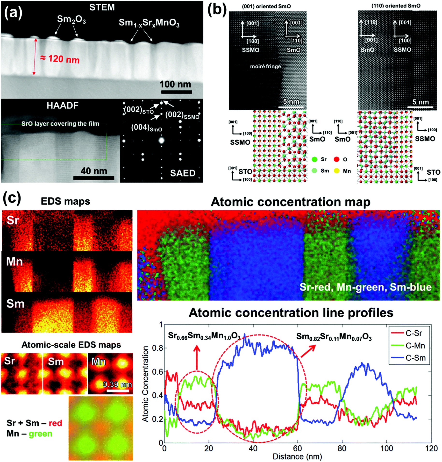 | ||
| Fig. 1 (a) High resolution cross sectional TEM image of the nanocomposite film (top). High-angle annular dark field (HAADF) image (bottom left) as well as selected area electron diffraction (SAED) (bottom right). (b) High resolution TEM image showing the interface between the nanopillar and matrix (top). Crystal orientation representation of the nanopillar and matrix as well as the substrate (bottom). (c) EDS map showing the compositions of the nanopillars and matrix (top left and top right). Atomic-scale EDS maps (bottom left) showing Sr and Sm occupying the same sites in the perovskite lattice and the atomic concentration line profile (bottom right) showing the lateral compositions of the nanopillars and matrix. | ||
A high resolution cross-sectional TEM image of a nanocomposite film shows a clean and sharp interface between the SmO nano-pillars and the SSMO matrix (see Fig. 1(b)). Two different orientations of the SmO nano-pillars were observed, (110) and (001) while only one orientation of SSMO was observed, (001). As shown in the schematic crystal in the lower part of Fig. 1(b), the (110) SmO phase was oriented with the STO substrate in-plane with the [110] SmO||[100] STO. On the other hand, the (001) SmO was oriented in-plane with the [100] SmO||[100] STO. The SSMO phase was oriented in-plane with the [100] SSMO||[100] STO.
The occurrence of the (110) orientation of SmO in the nanocomposite film is different from the case of single phase SmO films grown on the (001) STO which are typically (001) oriented.42 The reason for this difference is that vertical epitaxial lattice matching between the [110] SmO and the [001] SSMO (0.9% misfit) in the (110) SmO films is much lower than the misfit between the [001] SmO and the [001] SSMO (6.6% misfit) in the (001) SmO films. Fig. 1(c) shows compositional characterization of the nanocomposite films by EDS, by atomic-scale EDS, by using atomic concentration maps, and by using atomic concentration line profiles. In the EDS maps, very sharp and clean interfaces can be observed from the bright regions for both Sr and Mn in the same area, with the bright region for Sm being in the adjacent area. The atomic-scale EDS maps show direct evidence of Sm substitution onto the Sr site. The atomic concentration maps and line profiles show the distinct nano-pillars of the composition Sm0.82Sr0.11Mn0.07O3 and the matrix of the composition Sm0.34Sr0.66MnO3. Hence, there is a ∼11% substitution of Sr onto Sm2O3 and ∼34% of Sm onto the Sr site in SrMnO3.
2θ-ω XRD scans of the nanocomposite films are shown in Fig. 2. Sharp peaks of the SSMO (002) and SmO (006) are observed in the Bragg–Brentano scan in Fig. 2(a) with some overlapping of the SSMO (002) and STO (001) peaks. No peaks associated with the (110) SmO were observed due to the overlapping of the SmO (440) with the STO (002) substrate peak. Owing to the poor crystallinity of the SrO phase on top of the nanocomposite film, even though it was observed in the high angle annular dark field (HAADF) image in Fig. 1(a), it was not observable by XRD in Fig. 2.
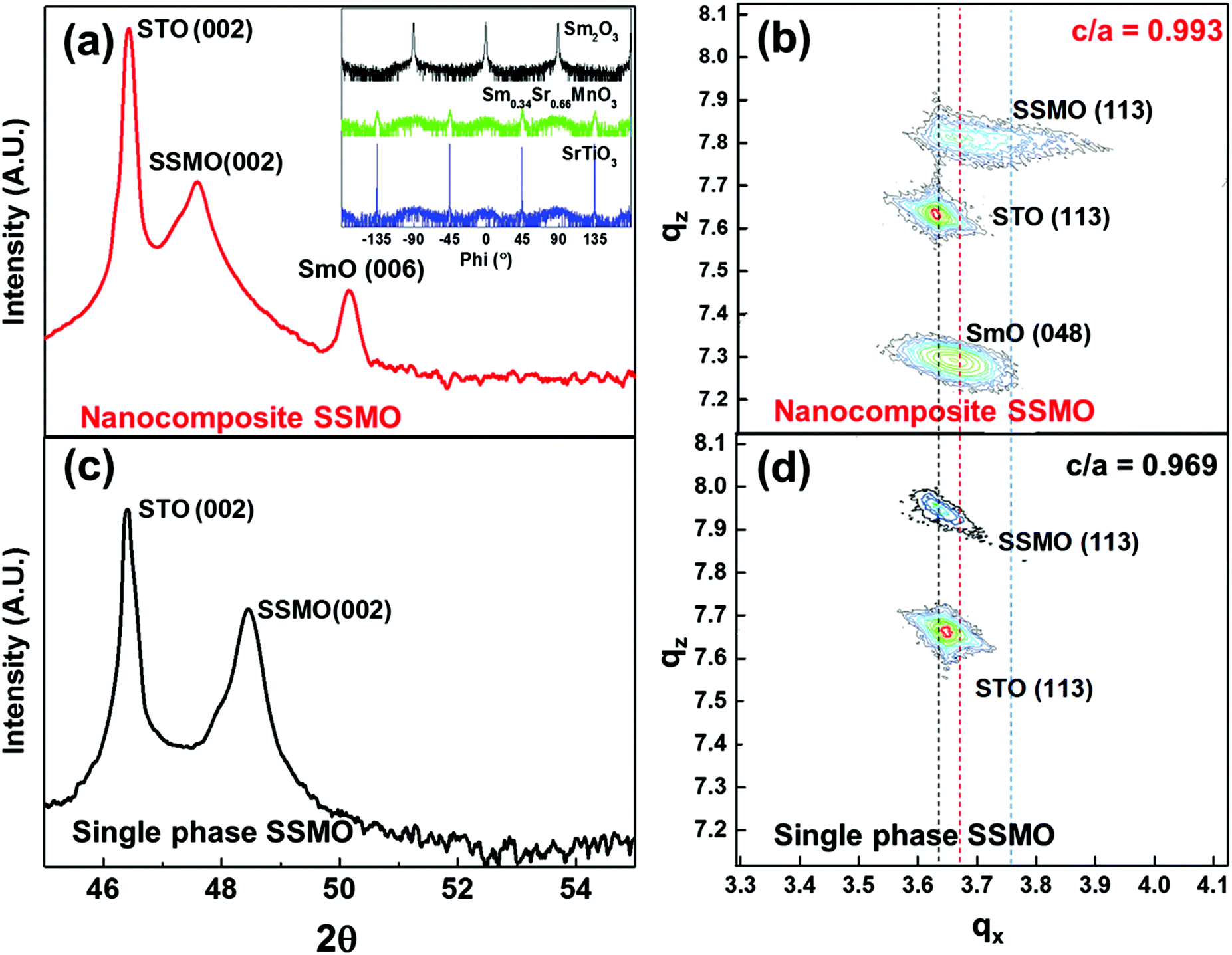 | ||
| Fig. 2 (a) 2θ-ω XRD scan of a nanocomposite film showing the presence of SmO and SSMO phases and the STO substrate, all with the (00l) orientation. The inset shows a phi-scan, revealing the different in-plane orientations of SmO and SSMO with respect to the STO substrate. (b) RSM of the nanocomposite film with vertical dashed lines indicating the centers of the peaks along qx (c) 2θ-ω XRD scan of a single phase SSMO film showing the presence of the SSMO film and the STO substrate, both with the (00l) orientation. (d) RSM of the single phase SSMO film showing close alignment along qx of the SSMO (113) peak with the STO (113) peak as a result of epitaxial growth which causes the SSMO in-plane lattice parameter to be equivalent to the STO in-plane lattice parameter. | ||
X-ray phi-scans of the STO substrate and the SSMO and SmO peaks in the nanocomposite (inset of Fig. 2(a)) show a cube-on-cube orientation of the SSMO on STO while the SmO shows a 45° in-plane rotation with respect to the STO substrate, consistent with the high resolution TEM images. Fig. 2(b) shows a reciprocal space map (RSM) of the nanocomposite film revealing the strain states of the phases in the nanocomposite film. As shown by the vertical dashed line, qx of the SSMO (113) peak is shifted to the left compared to bulk SSMO, indicating a higher a-axis in the nanocomposite film compared to the bulk. For comparison, Fig. 2(c) shows a 2θ-ω scan for a single phase SSMO film of the same thickness (∼100 nm). In the 2θ-ω scan the (002) SSMO peak is at a higher 2θ value of 48.4° compared to 47.6° for the nanocomposite, indicating that the nanocomposite film has a higher c parameter than the single phase film. Fig. 2(d) shows a reciprocal space map (RSM) of a single phase film. The SSMO (113) peak along qx is displaced further from the bulk SSMO position and hence the a-axis is larger than the one in the nanocomposite film. The different strain states obtained in the nanocomposite and single phase SSMO films are analyzed and discussed below.
The in-plane lattice parameters of the Sm0.34Sr0.66MnO3 phase in both the nanocomposite film and single phase SSMO films were estimated by first determining the out-of-plane parameter from the 2θ-ω scans, and then by using this value to extract the in-plane lattice parameter obtained from the RSM (113) peak. As shown in Table 1, the in-plane and out-of-plane lattice parameters in the nanocomposite film are 3.846 ± 0.016 Å and 3.819 ± 0.008 Å, respectively. These values are 1.61 ± 0.42% in tension in-plane and −2.05 ± 0.21% in compression out-of-plane relative to bulk Sm0.37Sr0.63MnO3, giving a c/a of 0.993 ± 0.024. In contrast, the in-plane and out-of-plane lattice parameters for the single phase SSMO film are 3.876 ± 0.009 Å and 3.756 ± 0.005 Å, respectively. These values are 2.40 ± 0.24% in tension in-plane and −3.67 ± 0.13% in compression out-of-plane relative to bulk Sm0.37Sr0.63MnO3, giving a c/a of 0.969 ± 0.014. The higher level of strain and overall low c/a in the single phase film arise because of the in-plane epitaxial straining from the STO substrate (a = 3.905 Å). The partial relaxation of the in-plane lattice parameter to 3.876 Å is expected owing to the relatively thick film. The out-of-plane compression arises through elastic strain to conserve the cell volume.
| Properties | Sm0.34Sr0.66MnO3 in the nanocomposite film | Single phase Sm0.34Sr0.66MnO3 film | Bulk Sm0.37Sr0.63MnO3 (ref. 36) (pseudo-cubic) |
|---|---|---|---|
| a Strain calculated relative to bulk Sm0.37Sr0.63MnO3. | |||
| Thickness | 120 nm | 100 nm | N.A. |
| a (Å) | 3.846 ± 0.016 | 3.876 ± 0.009 | 3.785 |
| c (Å) | 3.819 ± 0.008 | 3.756 ± 0.005 | 3.899 |
| In-plane strain (%) | 1.61 ± 0.42a | 2.40 ± 0.24a | N.A. |
| Out-of-plane strain (%) | −2.05 ± 0.21a | −3.67 ± 0.13a | N.A. |
| Tetragonality (c/a) | 0.993 ± 0.024 | 0.969 ± 0.014 | 1.030 |
| Magnetic properties | Ferromagnetic | Antiferromagnetic | Antiferromagnetic |
| T C/TN (K) | T C = 140 | T N = 100 | T N = 250 |
| Electrical properties | Insulating | Insulating | Insulating |
On the other hand, in the nanocomposite film the out-of-plane compression arises from vertical epitaxy with the stiff Sm2O3 nano-pillars. Here, for the (001) Sm2O3 orientation 3 unit cells of SSMO match with 1 unit cell of SmO (3 × 3.819 Å||1 × 10.93 Å), and for the (110) SmO orientation, 4 unit cells of SSMO match with 1 unit cell of SmO (4 × 3.819 Å||1 × 10.93 × √2Å). The in-plane tension arises because upon cooling the film from the growth temperature, the stiff Sm2O3 pillars with a lower coefficient of thermal expansion cause the vertically epitaxially coupled Sm0.34Sr0.66MnO3 to expand.40 The tension is less in the composite film compared to the single phase SSMO films because of the different mechanism of the strain control.
Resistance vs. temperature plots comparing a nanocomposite film to a single phase SSMO film are shown in Fig. 3(a). An insulating profile was observed throughout the measurement temperature range. Below 50 K, the resistance of both films is beyond the measurement limit. The electrical conduction mechanism at high temperatures follows the small polaron hopping (SPH) model.43,44 The resistance as a function of temperature is given by R(T) = AT![[thin space (1/6-em)]](https://www.rsc.org/images/entities/char_2009.gif) exp(EA/kBT), where EA is the activation energy for conduction, T is the temperature and A is a constant. The activation energy EA is determined by using linear fitting of the ln(R/T) vs. 1/T (dotted line in Fig. 3(a)), giving 94 meV for the nanocomposite film and 84 meV for the single phase SSMO film. Both these values are higher than the bulk SSMO value of 45–46 meV.45 This is consistent with reduction of the electrical conduction because of strain in the films (and in the nanocomposite case, defects along the vertical interfaces between the two phases).
exp(EA/kBT), where EA is the activation energy for conduction, T is the temperature and A is a constant. The activation energy EA is determined by using linear fitting of the ln(R/T) vs. 1/T (dotted line in Fig. 3(a)), giving 94 meV for the nanocomposite film and 84 meV for the single phase SSMO film. Both these values are higher than the bulk SSMO value of 45–46 meV.45 This is consistent with reduction of the electrical conduction because of strain in the films (and in the nanocomposite case, defects along the vertical interfaces between the two phases).
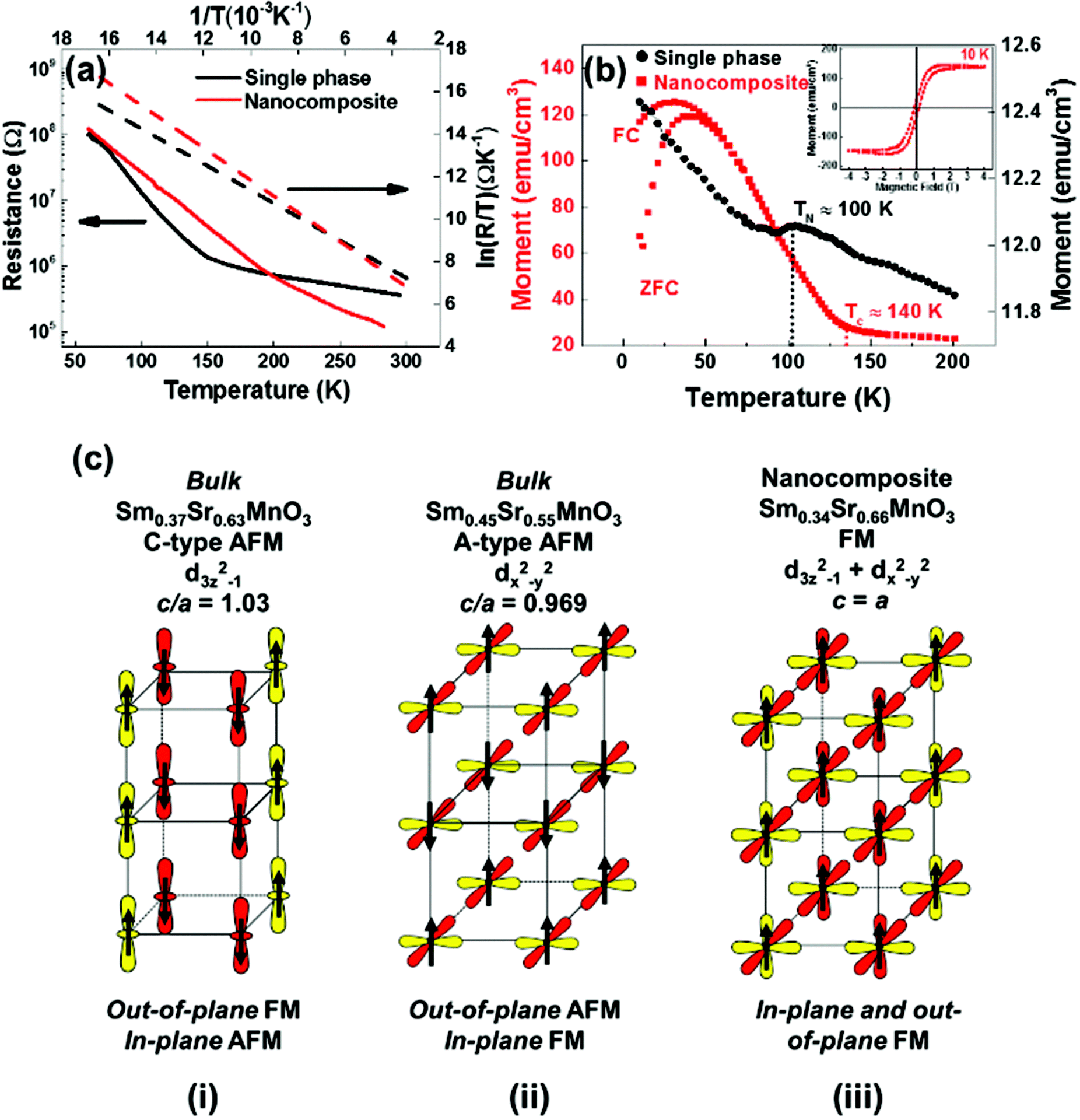 | ||
| Fig. 3 (a) Resistance vs. temperature plot comparing the nanocomposite to a single phase film. The dotted lines in the plot shows linear fitting of 1/T vs. ln(R/T). (b) Magnetization vs. temperature plot comparing the nanocomposite to a single phase film. The inset shows the magnetic hysteresis loop of the nanocomposite film. (c) Schematic diagram showing C-type and A-type AFM orbitals as well as FM orbitals with DE denoting double exchange coupling and SE denoting super-exchange coupling. | ||
The comparative magnetic properties of the nanocomposite and single phase SSMO films are shown in Fig. 3(b). M vs. T plots show ferromagnetism with a TC of 140 K for the nanocomposite film. We note that in the literature the highest TC value in the ferromagnetic insulating (FMI) Sr-doped SmMnO3 system is 100 K22 which is for the optimally doped (25% Sr doped) composition, and so the TC of the SSMO phase formed in our nanocomposite films is 40 K higher than for any FMI Sr-doped SmMnO3 phase. In addition, the TC of our nanocomposite films is 10 K higher than for the ferromagnetic metal (FMM), Sr-doped SmMnO3 (48% Sr).46
A cluster-glass like behaviour with a strong bifurcation between the field-cooled (FC) and zero field-cooled (ZFC) at 50 K was observed and the proposed origin of this is discussed later.47 The inset of Fig. 3(b) shows the magnetic hysteresis loop of M vs. H at 10 K for the nanocomposite film. After subtracting the paramagnetic background from the substrate and Sm2O3, a clear ferromagnetic hysteresis loop is obtained. The coercivity (HC) and saturation magnetic moment (MS) are 100 Oe and 146 emu cm−3 (1.93μB/Mn), respectively. This is comparable to the optimum 25% Sr doped SmMnO3 phase, as mentioned above.22
For the single phase SSMO films, AFM behavior was observed with a TN of 100 K (Fig. 3(b)).20 This is comparable to bulk Sm0.34Sr0.66MnO3 which shows C-type antiferromagnet behaviour, although the TN is higher for the bulk at ∼250 K, consistent with the very different levels of tetragonal distortion (c/a = 0.969 for the single phase films vs. 1.030 for the bulk, as shown in Table 1).
We now turn to gain an understanding of the magnetic properties of the plain versus nanocomposite films obtained in this study. In doped manganites, magnetic interactions between the Mn atoms are determined by competition between FM double exchange interactions and AFM super-exchange.48 The origin of the magnetic properties in the nanocomposite films can be understood by first realising that the level of structural distortion strongly influences these interactions. With Jahn–Teller effects at play, small distortions of MnO6 can stabilize either of the eg orbitals, 3z2 − r2 or x2 − y2. For c/a > 1 (c/a < 1), the MnO6 octahedra are tensed (compressed) and consequently the 3z2 − r2 (x2 − y2) orbitals are energetically favoured over the x2 − y2 (3z2 − r2) orbitals.
Hence, for c/a >1 the 3z2 − r2 orbitals have a higher occupancy. This results in 1-D FM double exchange interactions along the out-of-plane direction. The 1-D FM columns are AFM owing to super-exchange coupling. This results in a C-type AFM structure (as shown in Fig. 3(c i)). This is the case for bulk Sm0.37Sr0.63MnO3, c/a = 1.03 (Table 1).
For c/a < 1, the x2 − y2 orbitals have a higher occupancy. This leads to strong double exchange coupling in the MnO2 planes which strengthens the ferromagnetic ordering in-plane. At the same time, super-exchange coupling stabilizes the antiferromagnetic ordering in the out-of-plane direction. This results in an A-type AFM as shown in Fig. 3(c ii). This is the case for the single phase Sm0.37Sr0.63MnO3 films, c/a = 0.969 (Table 1).
In our Sm0.34Sr0.66MnO3 nanocomposite films, c/a = 0.993 ± 0.024 (Table 1). Hence, the tetragonal distortion is reversed compared to the bulk value. Because c is close to a there is more or less equal occupation of the x2 − y2 and 3z2 − r2 orbitals which produces double exchange interactions in both the in-plane and out-of-plane directions, thus leading to ferromagnetic ordering in 3-dimensions (as shown in Fig. 3(c iii)).48
Besides the extent of tetragonal distortion in the films, we should consider the actual Mn–O–Mn bond lengths. This is because AFM super-exchange interactions depend on Mn–O distances more strongly than the FM double exchange interactions. Hence, longer Mn–O bond lengths make the AFM super-exchange coupling weaker, whereas they influence the FM double exchange much less.49 Hence, in our films FM double exchange dominates over AFM super-exchange, leading to the observed FM behavior. Overall, however, the AFM interactions in the film compete with the FM interactions. This competition explains the cluster glass-like behaviour in the M vs. T plot below 50 K in Fig. 3(b).
On a final note, the creation of high TC ferromagnetism in our nanocomposite films is achieved via strain coupling between two phases. The work parallels artificial super-lattice (SL) studies where magnetic phases are coupled to other phases in a parallel configuration. In the SL studies, strong enhancements of TC have been found when the in-plane strain is controlled by lateral coupling of phases. A TC of 650 K (increased by nearly 300 K compared to bulk and plain films) has been observed for LSMO–BTO (with in-plane straining of the LSMO by 1%).50 A key difference between the SL films and the nanocomposite films is that the nanocomposite films self-assemble rather than being made by a complex layering process.
In summary, in nanocomposite Sm0.34Sr0.66MnO3 (SSMO) films using self-assembled vertical, strain controlling SmO nanopillars embedded in the SSMO matrix, a low c/a ratio is induced in the SSMO. Essentially, using nanocomposite films has enabled us to create a ferromagnetic insulator in a relatively thick film out of an otherwise antiferromagnetic insulator. The strain states (in both magnitude and uniformity) induced using the nanocomposite approach cannot be realised in single phase films and hence a new dimension for property control is realized by using these structures.
Experimental
Nanocomposite films of Sm0.34Sr0.66MnO3–Sm2O3 were grown on the (001) SrTiO3 substrates using pulsed laser deposition (PLD). The starting target materials for PLD were prepared using a stoichiometric mixture of Sm2O3 + SrCO3 + MnO2 powders by solid state sintering at 1100 °C for 6 hours. A Lambda Physik KrF excimer laser (λ = 248 nm) was used for target ablation. The laser energy density was set at 1 J cm−2 with a target-to-substrate distance of 4.5 cm and 1 Hz pulse repetition rate. The vertical nanocomposite films were grown at 750 °C and 20 Pa oxygen pressure, followed by a short post deposition annealing at the same temperature for 30 minutes under a 100 mbar oxygen atmosphere. The resulting thickness of the film is 120 nm.A Panalytical high resolution X-ray diffractometer (with Cu Kα radiation, a 2-bounce hybrid monochromator and 0.5 mm slit beam tunnel) was used to determine the phase and crystalline quality of the deposited films. Cross-sectional images of the film were obtained by high resolution transmission electron microscopy (HRTEM). Platinum contacts were deposited by standard magnetron DC sputtering to serve as the top contact for electrical measurement. Magnetic properties were characterized using a superconducting quantum interference device (SQUID).
Conclusions
Nanocomposite films containing Sm0.34Sr0.66MnO3 were grown on SrTiO3 (001) with 120 nm thickness. Stiff Sm2O3 nanopillars formed in the matrix of Sm0.34Sr0.66MnO3, gave a unique strain state of lower in-plane tensile and out-of-plane compression than can otherwise be realized in single phase films. This leads to a lower c/a value compared to both the single phase films and bulk. This c/a reduction leads to 140 K ferromagnetism and insulating behaviour. This work demonstrates a novel strain approach for tuning magnetic properties in thin films.Acknowledgements
This work was supported by the European Research Council (ERC) (Advanced Investigator grant ERC-2009-AdG-247276-NOVOX). A. Suwardi would also like to acknowledge the Agency for Science, Technology and Research (A*STAR), Singapore for funding his graduate studies. M. E. Vickers is thanked for her help with the X-ray characterization work and A. Sangle for helping with the initial experimental work.Notes and references
- W. Prellier, M. Singh and P. Murugavel, J. Phys.: Condens. Matter, 2005, 17, R803 CrossRef CAS.
- W. Eerenstein, N. Mathur and J. F. Scott, Nature, 2006, 442, 759–765 CrossRef CAS PubMed.
- R. Ramesh and N. A. Spaldin, Nat. Mater., 2007, 6, 21–29 CrossRef CAS PubMed.
- J. Moodera, X. Hao, G. Gibson and R. Meservey, Phys. Rev. Lett., 1988, 61, 637 CrossRef CAS PubMed.
- P. LeClair, J. Ha, H. Swagten, J. Kohlhepp, C. Van de Vin and W. De Jonge, Appl. Phys. Lett., 2002, 80, 625–627 CrossRef CAS.
- N. S. Rogado, J. Li, A. W. Sleight and M. A. Subramanian, Adv. Mater., 2005, 17, 2225–2227 CrossRef CAS.
- M. Singh, K. Truong and P. Fournier, Appl. Phys. Lett., 2007, 91, 2504 Search PubMed.
- J. S. Moodera, J. Nowak and R. J. van de Veerdonk, Phys. Rev. Lett., 1998, 80, 2941 CrossRef CAS.
- T. S. Santos and J. S. Moodera, Phys. Rev. B: Condens. Matter Mater. Phys., 2004, 69, 241203 CrossRef.
- F. Natali, B. J. Ruck, N. O. Plank, H. J. Trodahl, S. Granville, C. Meyer and W. R. Lambrecht, Prog. Mater. Sci., 2013, 58, 1316–1360 CrossRef CAS.
- U. Lüders, M. Bibes, K. Bouzehouane, E. Jacquet, J.-P. Contour, S. Fusil, J.-F. Bobo, J. Fontcuberta, A. Barthélémy and A. Fert, Appl. Phys. Lett., 2006, 88, 2505 CrossRef.
- M. Bowen, M. Bibes, A. Barthélémy, J.-P. Contour, A. Anane, Y. Lemaıtre and A. Fert, Appl. Phys. Lett., 2003, 82, 233–235 CrossRef CAS.
- A. Haghiri-Gosnet and J. Renard, J. Phys. D: Appl. Phys., 2003, 36, R127 CrossRef CAS.
- M. Bibes, J. E. Villegas and A. Barthelemy, Adv. Phys., 2011, 60, 5–84 CrossRef CAS.
- H. Hwang, Y. Iwasa, M. Kawasaki, B. Keimer, N. Nagaosa and Y. Tokura, Nat. Mater., 2012, 11, 103–113 CrossRef CAS PubMed.
- E. Dagotto, T. Hotta and A. Moreo, Phys. Rep., 2001, 344, 1–153 CrossRef CAS.
- Y. Tokura and N. Nagaosa, Science, 2000, 288, 462–468 CrossRef CAS PubMed.
- M. Gajek, M. Bibes, A. Barthélémy, K. Bouzehouane, S. Fusil, M. Varela, J. Fontcuberta and A. Fert, Phys. Rev. B: Condens. Matter Mater. Phys., 2005, 72, 020406 CrossRef.
- M. Gajek, M. Bibes, S. Fusil, K. Bouzehouane, J. Fontcuberta, A. Barthelemy and A. Fert, Nat. Mater., 2007, 6, 296–302 CrossRef CAS PubMed.
- A. Kurbakov, A. Lazuta and V. Ryzhov, J. Phys.: Conf. Ser., 2010, 200, 012099 CrossRef.
- B. Prasad, M. Egilmez, F. Schoofs, T. Fix, M. E. Vickers, W. Zhang, J. Jian, H. Wang and M. G. Blamire, Nano Lett., 2014, 14, 2789–2793 CrossRef CAS PubMed.
- B. Prasad, W. Zhang, J. Jian, H. Wang and M. G. Blamire, Adv. Mater., 2015, 27, 3079–3084 CrossRef CAS PubMed.
- M. Egilmez, M. Abdelhadi, Z. Salman, K. Chow and J. Jung, Appl. Phys. Lett., 2009, 95, 2505 CrossRef.
- M. Kasai, H. Kuwahara, Y. Tomioka and Y. Tokura, J. Appl. Phys., 1996, 80, 6894–6897 CrossRef CAS.
- H. Oshima, K. Miyano, Y. Konishi, M. Kawasaki and Y. Tokura, Appl. Phys. Lett., 1999, 75, 1473 CrossRef CAS.
- M. Srivastava, M. Singh, P. Siwach, A. Kaur, F. Razavi and H. Singh, Solid State Commun., 2012, 152, 138–141 CrossRef CAS.
- M. K. Srivastava, M. Singh, A. Kaur, F. Razavi and H. Singh, J. Appl. Phys., 2011, 110, 123922 CrossRef.
- M. K. Srivastava, P. Siwach, A. Kaur and H. K. Singh, IEEE Trans. Magn., 2011, 47, 2486–2489 CrossRef CAS.
- E. Dagotto, New J. Phys., 2005, 7, 67 CrossRef.
- J. Gazquez, S. Bose, M. Sharma, M. Torija, S. J. Pennycook, C. Leighton and M. Varela, APL Mater., 2013, 1, 012105 CrossRef.
- E. M. Choi, T. Fix, A. Kursumovic, C. J. Kinane, D. Arena, S. L. Sahonta, Z. Bi, J. Xiong, L. Yan and J. S. Lee, Adv. Funct. Mater., 2014, 24, 7478–7487 CrossRef CAS PubMed.
- E.-M. Choi, A. Kursumovic, O. J. Lee, J. E. E. Kleibeuker, A. Chen, W. Zhang, H. Wang and J. L. MacManus-Driscoll, ACS Appl. Mater. Interfaces, 2014, 6, 14836–14843 CAS.
- M. Singh, K. Truong, P. Fournier, P. Rauwel, E. Rauwel, L. Carignan and D. Ménard, Appl. Phys. Lett., 2008, 92, 112505–112505 CrossRef.
- K. Ueda, Y. Muraoka, H. Tabata and T. Kawai, Appl. Phys. Lett., 2001, 78, 512 CrossRef CAS.
- D. Dunstan, S. Young and R. Dixon, J. Appl. Phys., 1991, 70, 3038–3045 CrossRef.
- A. Kurbakov, C. Martin and A. Maignan, Phys. Solid State, 2008, 50, 275–282 CrossRef CAS.
- J. L. MacManus-Driscoll, P. Zerrer, H. Wang, H. Yang, J. Yoon, A. Fouchet, R. Yu, M. G. Blamire and Q. Jia, Nat. Mater., 2008, 7, 314–320 CrossRef CAS PubMed.
- D. S. Gunn, N. L. Allan and J. A. Purton, J. Mater. Chem. A, 2014, 2, 13407–13414 CAS.
- S. Sankarrajan, S. Aravindan, M. Rajkumar and V. Rajendran, J. Alloys Compd., 2009, 485, 17–25 CrossRef CAS.
- J. MacManus-Driscoll, A. Suwardi, A. Kursumovic, Z. Bi, C.-F. Tsai, H. Wang, Q. Jia and O. J. Lee, APL Mater., 2015, 3, 062507 CrossRef.
- W. Jung and H. L. Tuller, Energy Environ. Sci., 2012, 5, 5370–5378 CAS.
- H. Yang, H. Wang, H. Luo, D. Feldmann, P. Dowden, R. DePaula and Q. Jia, Appl. Phys. Lett., 2008, 92, 62905–62905 CrossRef.
- D. Worledge, G. J. Snyder, M. Beasley, T. Geballe, R. Hiskes and S. DiCarolis, J. Appl. Phys., 1996, 80, 5158–5161 CrossRef CAS.
- R. Prasad, H. Singh, M. Singh, W. Prellier, P. Siwach and A. Kaur, J. Appl. Phys., 2008, 103, 3906 CrossRef.
- A. Hassen and P. Mandal, J. Appl. Phys., 2007, 101, 113917 CrossRef.
- C. Martin, A. Maignan, M. Hervieu and B. Raveau, Phys. Rev. B: Condens. Matter Mater. Phys., 1999, 60, 12191 CrossRef CAS.
- M. K. Srivastava, S. Singh, P. Siwach, A. Kaur, V. Awana, K. Maurya and H. Singh, AIP Adv., 2013, 3, 052118 CrossRef.
- B. Nanda and S. Satpathy, Phys. Rev. B: Condens. Matter Mater. Phys., 2008, 78, 054427 CrossRef.
- D. Kozlenko, N. Dang, Z. Jirák, S. Kichanov, E. Lukin, B. Savenko, L. Dubrovinsky, C. Lathe and C. Martin, Eur. Phys. J. B, 2010, 77, 407–411 CrossRef CAS.
- A. Sadoc, B. Mercey, C. Simon, D. Grebille, W. Prellier and M.-B. Lepetit, Phys. Rev. Lett., 2010, 104, 046804 CrossRef PubMed.
| This journal is © The Royal Society of Chemistry 2016 |