
 Open Access Article
 This Open Access Article is licensed under a
 Creative Commons Attribution 3.0 Unported Licence
Spatial resolution of tip-enhanced Raman spectroscopy – DFT assessment of the chemical effect†
Federico
Latorre
a,
Stephan
Kupfer
*a,
Thomas
Bocklitz
 ab,
Daniel
Kinzel
a,
Steffen
Trautmann
b,
Stefanie
Gräfe
a and
Volker
Deckert
*ab
ab,
Daniel
Kinzel
a,
Steffen
Trautmann
b,
Stefanie
Gräfe
a and
Volker
Deckert
*ab
aInstitute of Physical Chemistry and Abbe Center of Photonics, Friedrich-Schiller-University Jena, Helmholtzweg 4, 07743 Jena, Germany. E-mail: stephan.kupfer@uni-jena.de; volker.deckert@uni-jena.de
bLeibniz Institute of Photonic Technology, Albert-Einstein-Str. 9, 07745 Jena, Germany
First published on 22nd April 2016
Abstract
Experimental evidence of extremely high spatial resolution of tip-enhanced Raman scattering (TERS) has been recently demonstrated. Here, we present a full quantum chemical description (at the density functional level of theory) of the non-resonant chemical effects on the Raman spectrum of an adenine molecule mapped by a tip, modeled as a single silver atom or a small silver cluster. We show pronounced changes in the Raman pattern and its intensities depending on the conformation of the nanoparticle–substrate system, concluding that the spatial resolution of the chemical contribution of TERS can be in the sub-nm range.
1. Introduction
Improving spatial resolution is a major driving force for the development of microscopic techniques.1–6 In addition to the well-known fluorescence based methods, such as stimulated-emission-depletion (STED),1 photoactivated localization microscopy (PALM)2 and stochastic optical reconstruction microscopy (STORM),3 techniques based on near-field optics are capable of obtaining resolutions far beyond the diffraction limit.4–6 Plasmon-based systems are particularly successful in this respect, where a nanoscale plasmonic object confines the electromagnetic field and at the same time enhances the signal.7–15 Such systems are especially useful when fluorescence labeling cannot be used and intrinsic molecular information is required. The best known techniques based on plasmonic enhancement are surface and tip-enhanced Raman scattering (SERS and TERS, respectively)16–18 as well as tip enhanced infrared absorption (TEIRA).19,20 Signal enhancements observed in these techniques can be rationalized by two phenomena: the electromagnetic effect8,21–28 and the chemical effect.8,9,29–32 The former corresponds to the creation of a locally confined strong electric field by an incident light source, i.e. a plasmon, on a metallic cluster leading to a pronounced increase in the corresponding Raman signals of a substrate near the metal. The latter chemical effect is correlated to the interactions between molecules and metallic clusters and can be divided into three different contributions: ground state interactions between substrate and nanoparticle (non-resonant contribution), resonant enhancements of local (molecule) excitations (resonant contribution), and the emergence of new charge transfer states between the substrate and the nanoparticle (charge-transfer contribution).8,9,33,34 These three contributions can lead to changes in the shape, spectral position and intensity of Raman bands due to changes in the local environment of the substrate under investigation.22Interestingly, several recent TERS experiments have strongly indicated spatial resolutions of 1 nm or smaller (i.e., single molecule resolution).35–41 Such high resolutions are unexpected considering the dimensions of the commonly used plasmonic nanoparticles.42,43 While a high resolution was predicted by Elfick and coworkers for tips with radii of 1 nm,44 this tip size is generally difficult to achieve, and radii of 10–20 nm are considered more realistic.45–48
Recently, Aizpurua et al. and Sánchez-Portal et al. presented full quantum electrodynamic descriptions of plasmonic cavities, demonstrating the resolution capabilities of plasmonic nanoparticles due to extremely confined enhanced fields that can explain sub-nanometer resolution via the atom-scale features of small metal clusters.49,50 Recent work on the resolution of TERS mapping, where mainly electromagnetic effects are discussed,23 suggest that the confinement of the electric field near a tip is even more pronounced than expected due to the enhanced field-interaction with the (induced) dipole of the molecule. Moreover, the electric field gradient and its impact on the sub-nanometer spatial resolution40,41,51 was evaluated theoretically52 and experimentally.53
Quantum mechanical investigations studying the electromagnetic effects of plasmons on the Raman scattering process of a molecule in the vicinity of a metal nanoparticle have been performed by Jensen et al. who introduced a computational methodology to study plasmonic field effects on a substrate in the scope of SERS by means of a hybrid method combining atomistic electrodynamics and quantum mechanics.48,54 Another approach by Dong et al. presents a quantum mechanical description of the interaction between the molecule and the metal tip, treated as a highly confined plasmonic field, using an electric field function.55
In contrast to the work of Aizpurua, Jensen and Dong, we will focus exclusively on the non-resonant chemical contributions to the signal enhancement/changes in TERS. We present the results of purely quantum chemical calculations based on density functional theory (DFT) to evaluate the spatial resolution of a metal tip acting on adenine by investigating the effect of minute lateral variations of the tip with respect to an individual sample molecule. Such position effects are generally not considered in the estimation of the chemical effects in SERS because a thermodynamically governed association of the metal particle and molecule (therefore, an optimized minimum energy geometry) can be assumed. However, in a TERS experiment, this assumption is not necessarily valid: the sample molecules are generally immobilized on a surface and, thus, cannot select specific sites on the plasmonic tip, allowing energetically unfavored conformations.
Adenine-silver nanoparticle interactions have already been the subject of several investigations of both experimental and theoretical studies using SERS56–59 and TERS.56,60–62 Here, we theoretically investigate “forced” tip-molecule conformations that can only be formed under TERS conditions and study the effects of such geometries on the Raman spectra with respect to the lateral resolution. This is intriguing because the specific local placement of a metal atom or metal cluster (as provided by the placement of the metal tip) with respect to a molecule can be considered a new unique molecule with specific and characteristic vibrational modes. In addition to the investigation of the lateral positioning, we also study the influence of the longitudinal metal-molecule distance. This is of specific interest for TERS experiments because the tip-sample distance is a crucial parameter that determines signal enhancement. Additionally, the investigation of tip-sample distance will provide an estimate of when the chemical effects start to play a major role. Thus, the quantum chemical calculations aim to unravel tip-sample interactions on a molecular scale and provide further spectral information due to non-resonant chemical effects.
Last but not least, a comparison between the effects of a single metal atom and a 20-atom metal cluster mimicking a metal tip will be shown, providing insight into second layer effects, e.g., how strongly the atoms “behind” the front-most atom influence the molecular structure and consequently the vibrational spectra.
2. Computational details
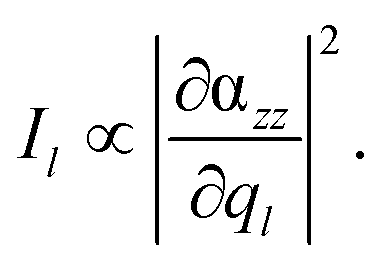
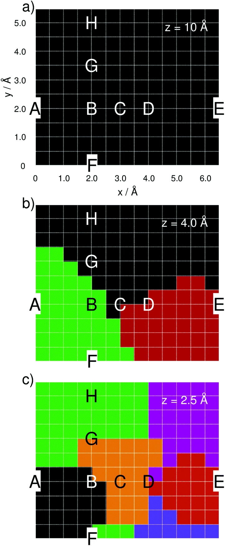
Two models have been utilized to simulate the interactions between one adenine molecule and a silver tip: (i) mimicking the tip using a single silver atom and (ii) describing the metal tip as a small, tetrahedral cluster consisting of 20 silver atoms. Although the description of a metal tip as merely one silver atom might seem too be oversimplified, experiments indicate that, even for typical tip radii of approximately 10–20 nm, the very top of the tip seems to consist of a single atom.45–48,50 Nevertheless, many effects are neglected in model (i), and model (ii) includes the effects of the second layer of atoms.All quantum chemical calculations were performed using the Gaussian 09 program.63 The planar adenine molecule, pre-optimized at the DFT level of theory using the range-separated CAM-B3LYP XC functional64 and the 6-311+G(d,p) triple-ζ basis set,65 was aligned within the xy-plane as depicted in Fig. 1(a).
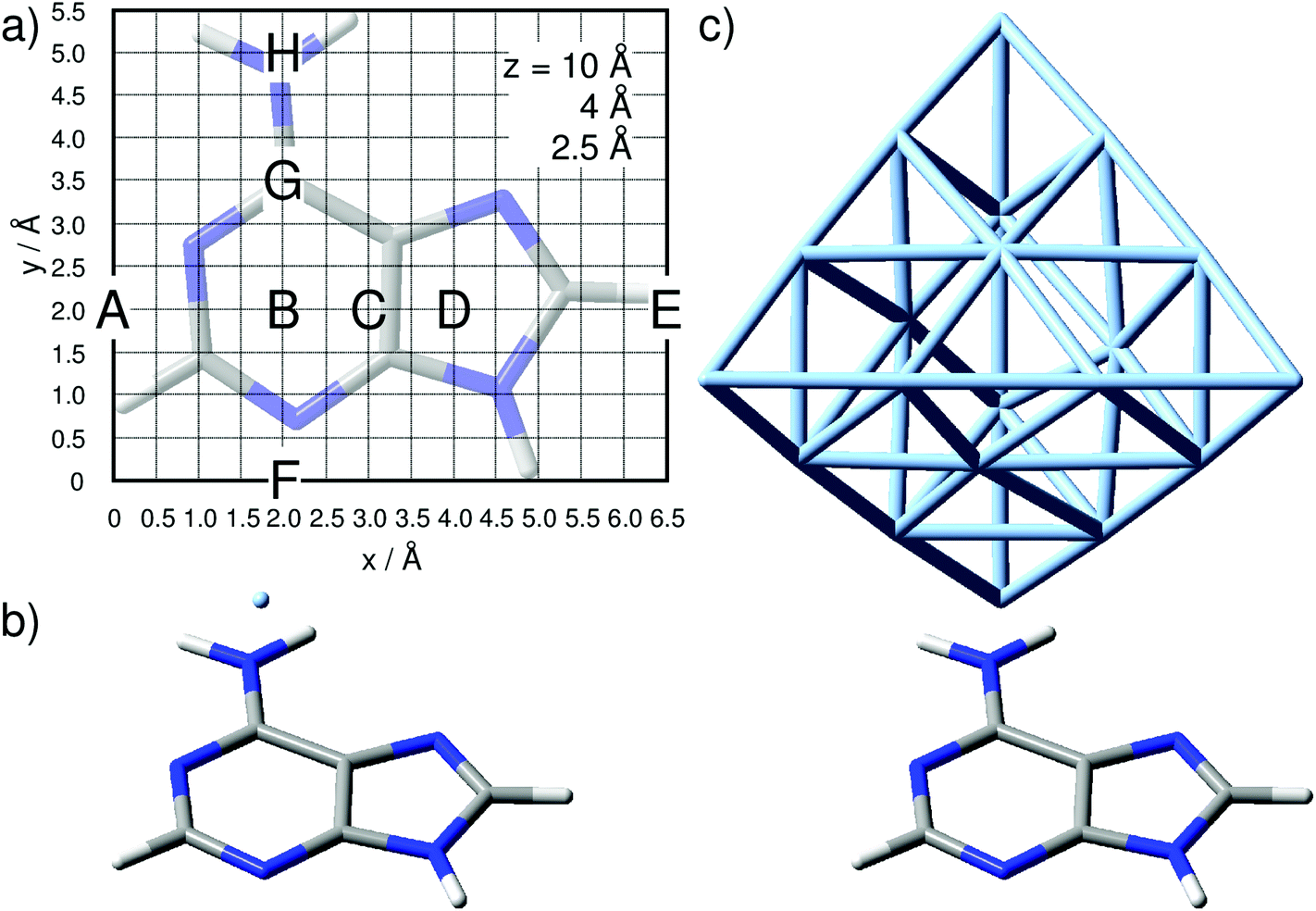 | ||
| Fig. 1 (a) Adenine orientation and computational grid of 6.5 Å times 5.5 Å and with a step size of 0.5 Å as used in the quantum chemical simulations. Tip positions labeled A–H are discussed in detail. Tip modeled by (b) one silver atom and (c) a tetrahedral cluster comprising 20 silver atoms. | ||
The silver tip – represented by either a single silver atom (model i) or a silver cluster comprised of 20 atoms (model ii) – was placed on top of the adenine and moved in a grid of 6.5 Å by 5.5 Å with a step size of 0.5 Å, leading to a total of 168 grid points, as depicted in Fig. 1, per layer (z-coordinate). The interactions of the “tip” approaching the adenine were simulated for layers of z = 10, 8, 6, 5, 4, 3, and 2.5 Å; only the three layers of z = 10, 4, and 2.5 Å are discussed in detail.
For all calculations where the tip was modeled by one silver atom (model i) in Fig. 1(b), a complete quantum mechanical description was used, which consequently leads to a doublet ground state. Single point calculations with the same XC functional and basis set and subsequent vibrational analyses for the aforementioned layers have been performed. For the silver, the MWB28 relativistic core potential66 was applied, where the inner shells are described by an effective core potential and the valence electrons (4s, 4p, 4d and 5s) explicitly with double-ζ quality. With respect to a realistic TERS setup with a substrate anchored parallel to a surface, and thus aligned in the xy-plane, the TERS signal is mainly obtained in the z-direction. Therefore, only the αzz-component of the polarizability tensor would be subjected to electromagnetic enhancement; thus, the Raman intensity Il of the lth vibrational normal mode is proportional to the absolute square of the derivative of αzz with respect to the normal coordinate (ql):
 | (1) |
The silver cluster (model ii) was oriented perpendicular to the xy-plane, while the vertex was placed accordingly on the grid (Fig. 1). Consequently, due to the even number of silver atoms, the singlet ground state was calculated for this model. As in the previous model (i), αzz was obtained by frequency calculations, and again, the relative Raman intensity of the lth mode is given by eqn (1).
To correct for the lack of anharmonicity and the approximate treatment of electron correlation, all vibrational frequencies were scaled by a factor of 0.95![[thin space (1/6-em)]](https://www.rsc.org/images/entities/char_2009.gif) 67 for both model (i) and model (ii) and broadened by Lorentzian functions with a full width at half maximum (FWHM) of 15 cm−1 to yield the Raman spectra. In order not to increase the computational demand of the grid calculations further, substrate-molecule interactions were not taken into account in this study. Such a simplification of the model system is valid in case of non-plasmonic surfaces that feature only weak chemical interactions at the substrate-molecule interface (e.g. mica). Furthermore, considering the uniform, specific substrate-molecule binding situation to be either unchanged or constant during the tip scanning along the grid may lead to spectral variations, however, the lateral resolution would not be decreased by including the substrate into the calculations.
67 for both model (i) and model (ii) and broadened by Lorentzian functions with a full width at half maximum (FWHM) of 15 cm−1 to yield the Raman spectra. In order not to increase the computational demand of the grid calculations further, substrate-molecule interactions were not taken into account in this study. Such a simplification of the model system is valid in case of non-plasmonic surfaces that feature only weak chemical interactions at the substrate-molecule interface (e.g. mica). Furthermore, considering the uniform, specific substrate-molecule binding situation to be either unchanged or constant during the tip scanning along the grid may lead to spectral variations, however, the lateral resolution would not be decreased by including the substrate into the calculations.
To identify similar groups of TERS spectra within one layer, that is, the spatial resolution, statistical analysis of all computed spectra has been performed using the statistical language R.68 In order to estimate such groups in the TERS grid, a principal component analysis followed by a k-means cluster analysis was carried out. In order to estimate the number of predefined clusters, e.g., the k value, vector normalization was performed, and the square root of the between-cluster variance and the total in-cluster variance was calculated. The fraction of the standard deviation (SD) between the clusters divided by the within-cluster SD of a layer was used as marker for the number of groups present in the dataset. The number of predefined clusters (k) was determined in such a way that the fraction of SD between the clusters and within-cluster SD was above 1, and the smallest possible k was chosen. The rationale behind this procedure is that the difference between the clusters should be higher than within the cluster, and therefore, the situation when there are equal differences was used to define k.
3. Results
3.1. One-silver-atom model
Starting from a distance of z = 10 Å between the silver atom and the molecular plane (xy-plane) of the pre-optimized adenine molecule, the Raman intensity pattern along the grid has been calculated for each vibrational normal mode using eqn (1). The simulated Raman spectra at 10 Å along the grid points share a uniform intensity pattern, which is almost identical to the z-polarized Raman spectrum of an isolated adenine molecule (see Fig. S1 in the ESI†). Reducing the z-distance to 8 Å and further to 6 Å does not affect the calculated polarizability derivatives significantly, and no pronounced spectral alterations are observed with respect to the previous layer. However, with the silver atom further approaching the molecular plane and reaching regions of chemical interaction, changes in the appearances of the Raman signals are expected. Indeed, a pronounced dependency of the Raman spectrum on the silver position is observed at 4 Å. While the silver induces only slight shifts of the vibrational frequencies (up to approximately 4 cm−1), indisputable alterations of intensity ratios and, thus, unique spectral patterns are found with respect to the specific lateral position of the silver atom.As found by Sun et al., enhancement due to resonance of charge transfer states between the molecule and the metal tip may influence the Raman intensity pattern substantially,33,34 therefore, we rule out such a potential resonance enhancement at an excitation wavelength of 532 nm by calculating (doublet) excited states of adenine with the converging silver atom based on TDDFT simulations (see Fig. S2 in the ESI† for details).
The following discussion focuses on the vibrational modes in the spectral range between 500 and 1700 cm−1. This region comprises the C–H and N–H vibrational normal modes, which are predominately affected in TERS.56,57,69 Hence, the integrated, or rather summed, signal intensity I of each grid-point (x, y, z) within this frequency range (8 ≤ l ≤ 37) is given by:
 | (2) |
Based on this expression, the integrated signal amplification A is obtained by normalization with respect to the minimum intensity Imin of the layer at z = 10 Å:
 | (3) |
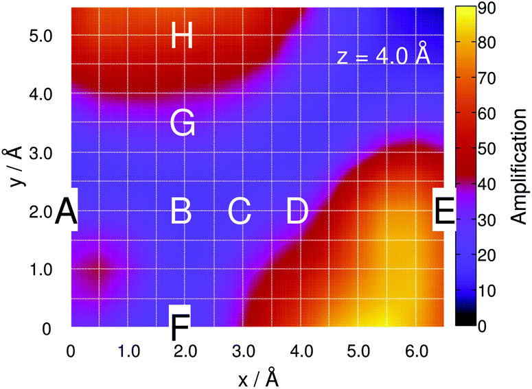
This site-specific intensity amplification for z = 10 Å is illustrated in Fig. 2(a).
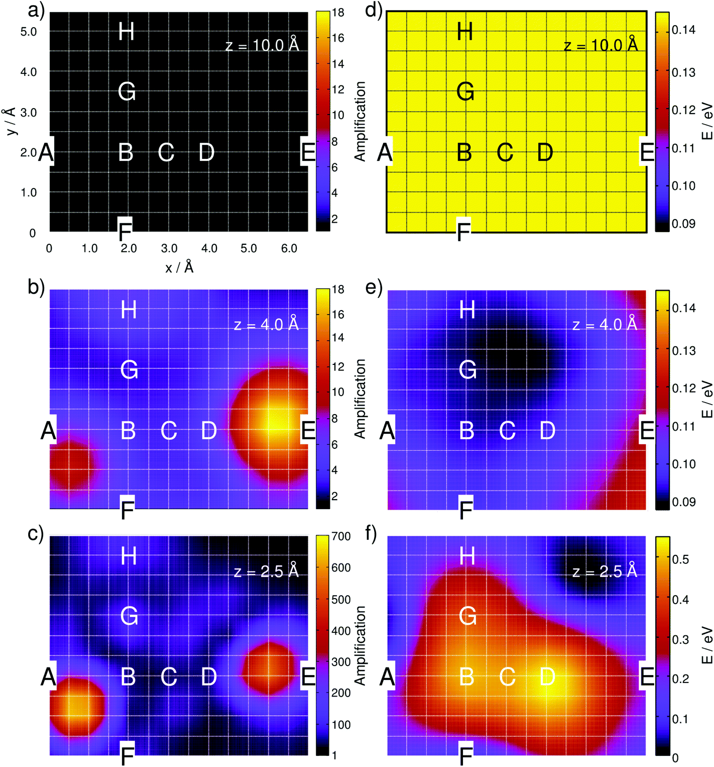 | ||
| Fig. 2 Simulated integrated Raman signal amplification based on eqn (3) along the grid at (a) z = 10 Å, (b) 4 Å and (c) 2.5 Å for the one-silver-atom model. (d)–(f) illustrate the relative ground state potential energy surfaces (E in eV) of the respective layers. Notice the adjusted color bars scales for the amplification and energy in (c) and (f). | ||
As expected, the intensity is independent of the “tip” position at this distance because the molecule interacts only very weakly with the silver atom. Hence, a constant value of A ≈ 1 is obtained along the grid. Lowering the silver atom to z = 4 Å, see Fig. 2(b), results in an average signal amplification of approximately 5.6 along the grid. However, locally, an amplification of up to 10.6 and 17.9 is observed for the tip positions on top of the C–H bonds of the pyrimidine and the imidazole moieties. Moving the silver atom closer to the molecular plane, i.e., to z = 2.5 Å, amplifies the integrated signal to an average value of 95.8. Then, as illustrated in Fig. 2(c), the grid-points on top of the C–H bonds feature the highest signal amplifications of 631.8 (pyrimidine) and 553.2 (imidazole), while the overall intensity profile along the entire grid shows a more pronounced structure than the layer at 4 Å.
In order to study the tip-induced alterations in more detail, five silver positions along the central line of the purine fragment (position A, B, C, D, and E) and four positions along the pyrimidine-amino axis (position F, B, G, and H) have been selected, see Fig. 1(a) for detailed positions. The point of intersection of both lines (B) is localized in the middle of the pyrimidine moiety. Selected spectra for each scan line at a height of z = 4 Å are shown in Fig. 3(a) and (b).
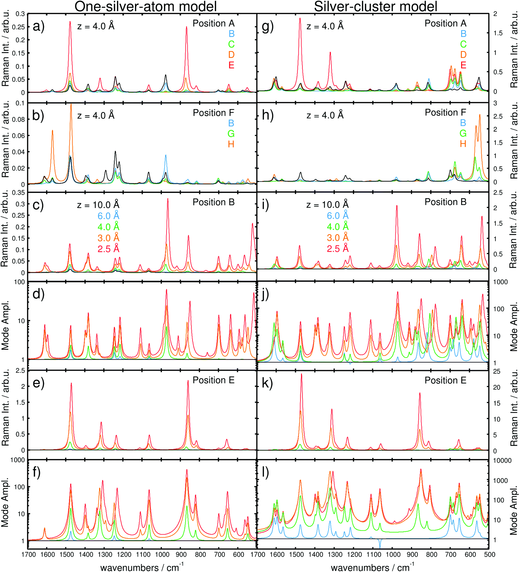 | ||
| Fig. 3 Simulated Raman spectra based on the one-silver-atom model for (a) the purine line at x = 2.0 Å (A, B, C, D, and E) and (b) the pyrimidine-amino line at y = 2.0 Å (F, B, G, and H) and a z-distance of 4.0 Å. The z-dependencies are shown for positions B and E at 10.0, 6.0, 4.0, 3.0, and 2.5 Å in Raman intensity (in arb. u.) in (c) and (e) and in mode amplification in (d) and (f), respectively. Raman spectra based on the silver-cluster model are shown in (g) and (h) for the purin and the pyrimidine line, while (i) and (k) illustrate the z-dependency at B and E (Raman Intensity in arb. u.). Mode amplifications (Al) in B and E are shown in (j) and (l). Vibrational normal modes were broadened by Lorentzians with a FWHM of 15 cm−1. Note the different scales for models (i) and (ii). | ||
The Raman spectra along the purine line are dominated by intense in-plane C–H bending modes. While for A and B, the C–H mode of the pyrimidine moiety (975–980 cm−1) shows the highest intensity, the spectra at D and E feature an intense C–H mode of the imidazole fragment (870–875 cm−1), Fig. 3(a). Position C exhibits C–H modes of both the pyrimidine and the imidazole moieties; however, the intensity of the C–H bending mode of the imidazole (870–875 cm−1) is considerably lower. Thus, position C can be addressed as a spectral intermediate of positions A and E or rather B and D.
In addition to the shape of the Raman pattern, a pronounced dependency with respect to the intensity or rather the mode amplification Al is also observed, which is defined as:
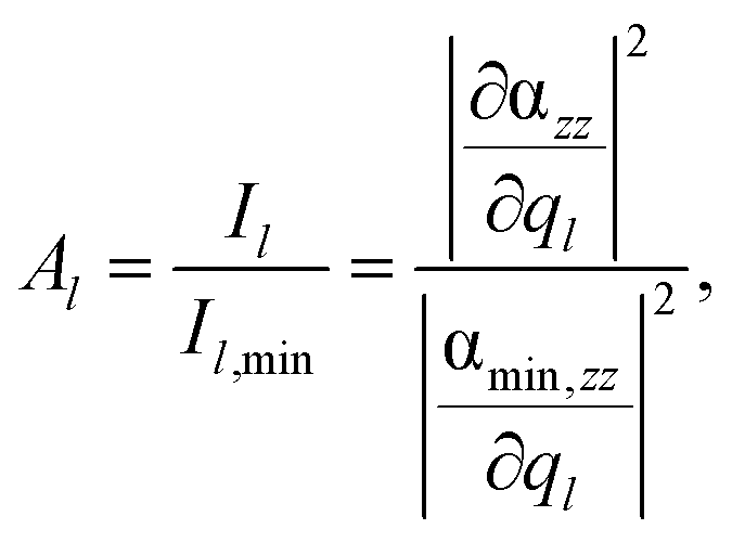 | (4) |
The positions A–D feature different spectral patterns, see Fig. 3(a), while further variations can be determined based on the maximal Al values ranging from approximately 2.8 in C to 13 in A (all for z = 4 Å).
However, at E (above the hydrogen atom), the Raman spectrum exhibits even larger mode amplifications of up to approximately 20 (for z = 4 Å).
This finding is in accordance with the results illustrated in Fig. 2(b), where the highest signal amplifications are observed in the region of the C–H bonds close to the positions A and E. By examination of the underlying Raman spectra, it is evident that the enormous local amplification in the region of the C–H bonds is correlated to the intense C–H bending modes of the pyrimidine and the imidazole fragments.
Analogously, the spectra along the pyrimidine-amino line position (F, B, G, and H) show a pronounced dependency with respect to the tip position. At F and H, intense C–H (pyrimidine) and amino bending modes (1470–1475 cm−1) dominate the pattern. Additionally, an intense characteristic N–H bending mode at approximately 1570 cm−1 is observed in H. The Raman spectra in B and G are of mixed character and feature characteristics of both F and H. Comparison of the spectra for these four positions, depicted in Fig. 3(b), yields a moderate mode amplification of merely 4.7 for F, 7.1 for B (explicitly shown in Fig. 3(c) and (d), and 2.4 for G, while H features values of Al ≥ 13 (all for z = 4 Å). Hence, the localization of the silver atom directly above a C–H (E) or N–H (H) bond induces a selective amplification of normal modes correlated to that specific position. Further convergence of the tip model towards the adenine (in the z-direction) substantially increases the interaction.
Consequently, the computed Raman spectra in each z-layer can be differentiated by means of the intensity pattern, and thus, by band shifts, deviations in the relative intensity, the absolute intensity and the mode amplification Al. To further investigate the Raman signal with respect to the “tip” position, the dependency in the longitudinal z-coordinate was evaluated. The general behavior of the intensity as a function of the metal-molecule distance (z-coordinate) is illustrated in Fig. 3(c) and (e) for positions B and E at z = 10.0, 6.0, 4.0, 3.0, and 2.5 Å, respectively, while the mode amplifications are presented in Fig. 3(d) and (f). At 10.0 Å, the spectra in B and E are identical and dominated by intense C–H and N–H bending modes. Starting at 4 Å, alterations are induced by the silver atom (see differences in the mode amplification and in the spectra; green lines in Fig. 3(d) and (f) as well as 3(c) and (e), respectively). At 3 Å, the spectrum in B is dominated by three intense CH/NH bending modes at 1490, 1390 and 980 cm−1; at the same distance in E, the Raman intensity pattern features two intense modes at 1490 and 880 cm−1 (CH/NH bending), both at higher absolute intensities compared to B. Moving the tip closer to z = 2.5 Å – corresponding to a repulsive interaction (see Fig. 2(f) and S3(b)†) – substantially alters the intensity pattern in B. Now, the intense CH bending mode (880 cm−1) is shifted by 12 cm−1 to lower frequencies, and an intense skeleton mode at 520 cm−1 emerges. In addition to the chemical shifts and the intensity pattern, the absolute intensity and, thus, the integrated amplification (eqn (3)) depend strongly on the “tip”-sample distance. Therefore, compared with 10 Å, distances of 8, 6, 5, 4, 3 and 2.5 Å have calculated amplification factors (A) of 1.1, 1.6, 2.2, 3.7, 14.8 and 34.4 for B and 1.2, 2.0, 3.8, 13.7, 83.9 and 165.3 for E, respectively.
By fitting the integrated intensity amplification A (eqn (3)) at position B along z to an exponential function, it is evident that the amplification decreases exponentially with the z-distance, see Fig. S3(a).†
The potential energy surface (PES) features attractive interactions of the silver atom and the adenine in the range of 6 to 3 Å, with the minimum at approximately 3.62 Å. At larger distances, the attractive interactions decay; therefore, the ground state energy increases towards the threshold of 0.06 eV. This trend is in agreement with the evolution of the amplification factors in the interval between 6 and 10 Å from 1.6 to 1.1 (8 Å) and 1.0 (Fig. S3a†). At small distances (z < 3Å), the PES is dominated by repulsive interactions and consequently increases to 0.06 and 0.41 eV at 3.0 and 2.5 Å, respectively.
In order to unravel the pronounced dependency of the Raman intensity on the silver atom position, 2D PESs of the electronic ground state are presented in Fig. 2 for the grids at 10, 4 and 2.5 Å, i.e., in the long-range non-interactive region, close to the equilibrium distance and in the strongly repulsive region. As illustrated in Fig. 2(d) for the layer at z = 10 Å, an almost uniform energy landscape is obtained with deviations of less than 0.001 eV. Moving the silver atom to 4 Å induces pronounced alterations in the PES, as depicted in Fig. 2(e); these changes originate from attractive interactions between the silver and the molecule. Hence, in general, the energy of the system is stabilized, while the minimum energy at this layer is localized between the amino-group and the nearby nitrogen atom of the imidazole moiety, where a stabilization of approximately 0.05 eV is calculated with respect to the former layer (10 Å). By moving the silver atom even closer to 2.5 Å, strong repulsive interactions between the silver and the adenine are observed, which can be easily seen in Fig. 2(f). The strongest (repulsive) interactions are found at positions B (0.50 eV) and D (0.54 eV), i.e., in the centers of the pyrimidine and the imidazole moieties. The global minimum energy is localized close to the non-protonated nitrogen of the imidazole; this grid point exhibits the lowest potential energy of all three layers depicted in Fig. 2(d)–(f).
To rationalize the local effects of the silver atoms on the Raman spectrum as well as on the potential energy landscape, the electronic wave function and the frontier orbitals of the adenine and the silver are studied in detail. Due to the odd number of electrons of the silver atom (4d10·5s1), the electronic ground state of the adenine-silver system is a doublet, where the 5s orbital of the silver is occupied in α-spin but unoccupied in β-spin, also known as a semi-occupied molecular orbital (SOMO). The first orbital occupied in both α- and β-spin is the highest bonding π-orbital of the adenine. In order to study interactions among these orbitals, a linear combination of the π-orbital (adenine) and the 5s-orbital (silver) was created, where the positive combinations are denoted π(α) + s(α) and π(β) + s(β) and the negative ones π(α) − s(α) and π(β) − s(β); more details with respect to this linear combination can be found in Fig. S4.† Based on these four orbitals occupied by three electrons, a bond order of 0.5 is obtained. At z = 10 Å the positive and negative linear combinations are almost degenerate; however, with the tip converging towards the adenine, this degeneration becomes abrogated, which is shown in Fig. 4 for the positions B and E in the 4 Å layer.
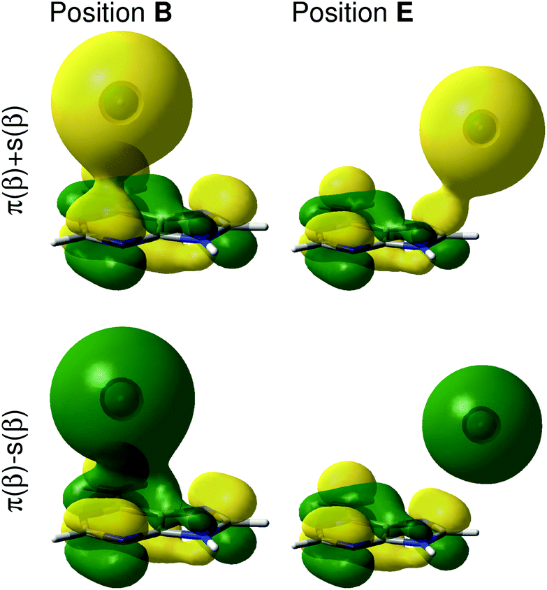 | ||
| Fig. 4 Constructed positive and negative linear combinations, π(β) ± s(β), of the highest occupied molecular orbital of the adenine and the 5s orbital of the silver atom with β spin for the positions B and E at z = 4 Å. | ||
It can be easily seen that the interaction of the 5s orbital with the π-system depends strongly on the silver atom position and eventually on the presence of a nodal plane between the silver and the adenine. For positions in the periphery of the molecule, e.g., in E, where the s-orbital of the silver interacts with the p-orbitals of the carbon atoms of the imidazole (see Fig. 4), only small interactions are observed. Here, a constructive overlap is obtained for the positive linear combination and a node for the negative linear combination. The orbital interactions in the center of the purine fragment are more complicated; constructive as well as destructive interactions are found for π + s as well as for π − s, as can be seen for position B in Fig. 4. Lowering the silver atom further towards the adenine consequently enhances the constructive and destructive orbital interactions. The spherical shape of the s-orbital leads to a manifold of delocalized interactions with the π-orbital, especially in the center of the pyrimidine and the imidazole rings. Hence, in these regions, a bonding situation is unfavorable, which can also be seen in the high potential energies in B and D in Fig. 2(f).
To elucidate the resolution of a TERS experiment, where positioning accuracy is eventually limited by noise and drift in all three dimensions, a principal component analysis followed by a k-means cluster analysis was carried out using the computed z-polarized Raman spectra of the layers at 10.0, 4.0 and 2.5 Å. This analysis was done to account for averaging effects, which are expected due to the above-mentioned limitations of an actual experiment. The statistical analysis incorporates information with respect to the spectral pattern as well as with respect to the intensity. Fig. 5(a)–(c) illustrates these results for the aforementioned layers at 10.0, 4.0 and 2.5 Å.
 | ||
| Fig. 5 Spectral groups along the computational grid for the layers of 10.0 (a), 4.0 (b) and 2.5 Å (c) as obtained by statistical analysis. | ||
At z = 10.0 Å, the statistical analysis yields merely one spectral group, which corresponds to a uniform Raman pattern at this distance. Moving the silver atom to 4.0 and then to 2.5 Å yields three and six spectral groups, respectively. The average spectra within each spectral group are illustrated in Fig. S5 of the ESI.† The obtained spectral groups along the grid are in very good agreement with the computed amplifications of Fig. 2(a)–(c) and show that TERS with sub-nanometer resolution is possible depending on the distance between the tip and the substrate, even when considering noise and drift-induced variations of the actual tip position.
In the following section, the results obtained for the one-silver-atom model (i) will be compared to the enhanced silver-cluster model (ii).
3.2. Silver-cluster model
To verify the results obtained for the one-silver-atom model presented in section 3.1, as well as to investigate a dependency with respect to the tip size, pre-selected traces on the molecule as well as the entire layer at z = 4 Å have been calculated with the 20-silver-atom tip model. This model considers chemical effects of the silver atoms in the second, third and fourth layers of the tetrahedral cluster on the TERS signals. Analogous to section 3.1, we present the evolution of the z-polarized Raman signal for the 2D layer at 4 Å, while particular emphasis was set on the purine line (positions A, B, C, D and E) and on the pyrimidine-amino line (positions F, B, G and H). In addition, the z-dependency and, hence, the signal amplification in z, is evaluated at positions B and E.First, the results on the z-dependency are presented. Calculations at z = 10, 6, 4, 3 and 2.5 Å were performed at B and E. The integrated amplification is defined using the intensity (see eqn (2)) divided by the intensity at z = 10 Å. A very similar behavior of the amplification with respect to z is obtained for both models. Interestingly, the amplification is even larger with the silver-cluster model. While, by definition, a value of A = 1 is obtained at 10 Å, upon approach, the amplification at position B increases to 5.1, 18.1, 51.8 and 105.1 at 6, 4, 3 and 2.5 Å, respectively, see Fig. S6(a).† At E, even larger amplifications of 7.7, 63.8, 363.1 and 747.0 (at 6, 4, 3 and 2.5 Å) are calculated, in accordance with the results obtained for the one-silver-atom model, where amplifications of 34.4 and 165.3 (z = 2.5 Å) were computed for B and E. Interestingly, the potential minimum and thus the bonding region of the cluster and the adenine is offset from 3.62 to 3.14 Å, while the bonding energy increased from 0.06 to 0.22 eV, see Fig. S6(b).†
Second, the dependency of the signal amplification as well as the spectral pattern along the purine and the pyrimidine-amino line at z = 4 Å is shown in Fig. 3(g) and (h). The z-polarized Raman spectra along the purine line [Fig. 3(g)A, B, C, D and E] feature similar intensities in A to D, while the intensity in E close to the imidazole C–H bond is substantially enhanced. Superficially, the spectra obtained with the silver-cluster model seem similar to the ones obtained with the one-silver-atom model. In accordance with the results obtained with the one-silver-atom model, the spectra in A and B are dominated by intense in-plane modes localized on the C–H group of the pyrimidine but also on the C–H and N–H groups of the imidazole and the amino group. E features mainly intense in-plane (xy-polarized) C–H and N–H modes of the imidazole moiety at approximately 1300 and 1500 cm−1, while C and D show contributions of all fragments and can be seen as spectral intermediates. In a similar manner, the spectra along the pyrimidine-amino line, see Fig. 3(h), are mainly dominated in A by C–H bending modes of the pyrimidine fragment and in H by N–H bending modes of the amino group polarized in the xy-plane, while the intermediate positions B and G show contributions from both functional groups. However, in contrast to the spectra in Fig. 3(a) and (b) (one-silver-atom model), all spectra calculated using the extended tip model have intense vibrational modes in the frequency range between 500 and 800 cm−1. These modes have exclusively out-of-plane character (z-polarized), where the modes between 500 and 600 cm−1 are correlated to the amino-group, those between 600 and 700 cm−1 to C–H and N–H modes of the imidazole fragment and those at approximately 800 cm−1 to frame modes. Similar to the frequency range between 800 and 1700 cm−1, modes localized close to the silver cluster are selectively increased, i.e., in H (and G) very intense amino modes with mode amplifications, Al, of up to 478.7 (and 131.8) are observed (500–600 cm−1). In C, D and E, C–H and N–H modes of the imidazole fragment dominate the fingerprint region, where Al values of up to 83.8, 119.2 and 200.0 were obtained, respectively (all for z = 4 Å).
The observed variations in the z-polarized Raman spectra with respect to the model size are predominantly accounted for by the amplification of all C–H and N–H out-of-plane modes with the silver cluster tip model. This is evident by comparing the amplifications at z = 4 Å for the one-silver-atom model and the silver-cluster model, see Fig. 2(b) and 6.
 | ||
| Fig. 6 Simulated Raman signal amplification based on eqn (3) along the grid at 4 Å for the silver-cluster model. | ||
In order to unravel the impact of the tip model size on the out-of-pane modes, the “tip” must be examined more closely. Both the silver atom and the 20-silver-atom tetrahedron feature, independently of the grid point, overall charges of approximately −0.1 (Mulliken charge). However, the four vertex positions of the silver cluster hold pronounced negative charges. At z = 10 Å, all four vertices are degenerate and feature partial charges of approximately −1.6, whereas at shorter z-distance, e.g., at 4 Å, this degeneration is abolished. Here, the “tip”-atom (vertex towards the molecule) features charges of up to −2.0 for grid points above the purine moiety. Hence, this charge, or rather the charge gradient, along z induces distinct chemical effects that mainly affect the z-polarized C–H and N–H out-of-plane modes.
This phenomenon can also be observed by the evolution of the Raman intensity, or rather mode amplification, at positions B and E with respect to the “tip” convergence, as depicted in Fig. 3(i)–(l). The Al values obtained using the silver-cluster model are larger than those obtained using the one-silver-atom model. This is especially evident at position E, where mode amplifications of up to approximately 3500 (z = 2.5 Å at 852 cm−1) were obtained using the silver cluster, while amplifications of only approximately 450 (z = 2.5 Å at 865 cm−1) were calculated for the one-silver-atom model.
4. Conclusions
In the present contribution, the possibility of sub-nanometer-resolution in TERS has been investigated by means of quantum chemical simulations at the DFT level of theory of an adenine molecule-silver tip model system. Three-dimensional grid calculations were performed for two models in which the silver tip was approximated by one silver atom or by a tetrahedron comprised of 20 silver atoms. Both computational models suggest a hypothetical TERS resolution in the Ångström regime. Pronounced dependencies of the simulated Raman patterns and intensities on the tip model and its position were found. Mode amplifications of up to almost 3500 were computed based on the chemical interactions between the adenine and the silver tip. From an experimental point of view, a sub-Ångström resolution is unrealistic at the moment due to, e.g., tip positioning noise and thermal drift of the sample. Such effects would result in a decreased lateral resolution based on signal averaging. However, the lateral contrast obtained in recent TERS experiments using scanning probe systems with sub-nanometer stability can now be explained to a certain extent. It is important to note that external fields, particularly the field confinement due to plasmonic effects, were not considered here. Only the molecular properties of the silver-adenine system were accounted for, while locally confined inhomogeneous electromagnetic fields and strong field gradients may increase the lateral resolution even further. Still, a surprisingly strong enhancement of the signals due to polarizability changes was observed. At first glance, the strong dependence of the spectra towards the local position of the metal seems disturbing; however, this dependence mainly influences the intensity ratios rather than the band positions. Consequently, for an assignment to a specific structure, the actual band positions are of higher importance than their intensity ratios.In summary, we think these findings will encourage further joint spectroscopic-theoretical investigations. In particular incorporating the plasmonic enhancement based on the interaction of the sample with the electric field and the electric field gradients, in the case of inhomogeneous fields, and chemical as well as chemical/plasmonic effects at the surface-substrate interface are envisioned in prospective studies.
Acknowledgements
T. B. gratefully acknowledges the support of the Federal Ministry of Education and Research within the project PhotoSkin (FKZ: 13N13243) and the funding by the 7th Framework Programme of the European Union for the project PhotoSkin. D. K. thanks the Abbe Center of Photonics for financial support within the ACP Explore project. All calculations were performed at the Universitätsrechenzentrum of the Friedrich-Schiller University of Jena and at the HP computers of the Theoretical Chemistry group in Jena.References
- S. Hell and J. Wichmann, Opt. Lett., 1994, 19(11), 780–782 CrossRef CAS PubMed.
- E. Betzig, G. H. Patterson, R. Sougrat, O. W. Lindwasser, S. Olenych, J. S. Bonifacino, M. W. Davidson, J. Lippincott-Schwartz and H. F. Hess, Science, 2006, 313(5793), 1642–1645 CrossRef CAS PubMed.
- M. J. Rust, M. Bates and X. Zhuang, Nat. Methods, 2006, 3(10), 793–796 CrossRef CAS PubMed.
- E. Betzig, J. K. Trautman, T. D. Harris, J. S. Weiner and R. L. Kostelak, Science, 1991, 251(5000), 1468–1470 CAS.
- E. J. Sánchez, L. Novotny and X. S. Xie, Phys. Rev. Lett., 1999, 82(20), 4014–4017 CrossRef.
- J. Y. Lee, B. H. Hong, W. Y. Kim, S. K. Min, Y. Kim, M. V. Jouravlev, R. Bose, K. S. Kim, I.-C. Hwang, L. J. Kaufman, C. W. Wong, P. Kim and K. S. Kim, Nature, 2009, 460(7254), 498–501 CrossRef CAS.
- M. Osawa, in Near-Field Optics and Surface Plasmon Polaritons, ed. S. Kawata, Topics in Applied Physics, Springer, Berlin Heidelberg, 2001, vol. 81, pp. 163–187 Search PubMed.
- S. M. Morton, D. W. Silverstein and L. Jensen, Chem. Rev., 2011, 111(6), 3962–3994 CrossRef CAS PubMed.
- L. Jensen, C. M. Aikens and G. C. Schatz, Chem. Soc. Rev., 2008, 37(5), 1061–1073 RSC.
- D. Cialla, A. März, R. Böhme, F. Theil, K. Weber, M. Schmitt and J. Popp, Anal. Bioanal. Chem., 2012, 403(1), 27–54 CrossRef CAS PubMed.
- L. Tong, T. Zhu and Z. Liu, Chem. Soc. Rev., 2011, 40(3), 1296–1304 RSC.
- S. Schlücker, Angew. Chem., Int. Ed., 2014, 53(19), 4756–4795 CrossRef PubMed.
- E. Bailo and V. Deckert, Chem. Soc. Rev., 2008, 37(5), 921–930 RSC.
- B. Pettinger, P. Schambach, C. J. Villagómez and N. Scott, Annu. Rev. Phys. Chem., 2012, 63(1), 379–399 CrossRef CAS PubMed.
- C. Blum, L. Opilik, J. M. Atkin, K. Braun, S. B. Kämmer, V. Kravtsov, N. Kumar, S. Lemeshko, J.-F. Li, K. Luszcz, T. Maleki, A. J. Meixner, S. Minne, M. B. Raschke, B. Ren, J. Rogalski, D. Roy, B. Stephanidis, X. Wang, D. Zhang, J.-H. Zhong and R. Zenobi, J. Raman Spectrosc., 2014, 45(1), 22–31 CrossRef CAS.
- R. M. Stöckle, Y. D. Suh, V. Deckert and R. Zenobi, Chem. Phys. Lett., 2000, 318(1–3), 131–136 CrossRef.
- N. Hayazawa, Y. Inouye, Z. Sekkat and S. Kawata, Opt. Commun., 2000, 183(1–4), 333–336 CrossRef CAS.
- M. S. Anderson, Appl. Phys. Lett., 2000, 76(21), 3130–3132 CrossRef CAS.
- B. Knoll and F. Keilmann, Nature, 1999, 399(6732), 134–137 CrossRef CAS.
- T. Taubner, F. Keilmann and R. Hillenbrand, Nano Lett., 2004, 4(9), 1669–1672 CrossRef CAS.
- N. Chiang, N. Jiang, D. V. Chulhai, E. A. Pozzi, M. C. Hersam, L. Jensen, T. Seideman and R. P. Van Duyne, Nano Lett., 2015, 15(6), 4114–4120 CrossRef CAS PubMed.
- M. Thomas, S. Mühlig, T. Deckert-Gaudig, C. Rockstuhl, V. Deckert and P. Marquetand, J. Raman Spectrosc., 2013, 44, 1497–1505 CrossRef CAS.
- C. Zhang, B.-Q. Chen and Z.-Y. Li, J. Phys. Chem. C, 2015, 119(21), 11858–11871 CAS.
- S. Corni and J. Tomasi, J. Chem. Phys., 2001, 114(8), 3739–3751 CrossRef CAS.
- S. Corni and J. Tomasi, Chem. Phys. Lett., 2001, 342(1–2), 135–140 CrossRef CAS.
- S. Corni and J. Tomasi, J. Chem. Phys., 2002, 116(3), 1156–1164 CrossRef CAS.
- S. Corni and J. Tomasi, J. Chem. Phys., 2002, 117(15), 7266–7278 CrossRef CAS.
- D. V. Chulhai and L. Jensen, J. Phys. Chem. C, 2013, 117(38), 19622–19631 CAS.
- L. Zhao, L. Jensen and G. C. Schatz, J. Am. Chem. Soc., 2006, 128(9), 2911–2919 CrossRef CAS PubMed.
- L. Jensen, L. L. Zhao and G. C. Schatz, J. Phys. Chem. C, 2007, 111(12), 4756–4764 CAS.
- S. Liu, X. Zhao, Y. Li, M. Chen and M. Sun, Spectrochim. Acta, Part A, 2009, 73(2), 382–387 CrossRef PubMed.
- F. Latorre, J. Guthmuller and P. Marquetand, Phys. Chem. Chem. Phys., 2015, 17(12), 7648–7658 RSC.
- L. Xia, M. Chen, X. Zhao, Z. Zhang, J. Xia, H. Xu and M. Sun, J. Raman Spectrosc., 2014, 45(7), 533–540 CrossRef CAS.
- M. Sun, Y. Fang, Z. Yang and H. Xu, Phys. Chem. Chem. Phys., 2009, 11(41), 9412–9419 RSC.
- R. Zhang, Y. Zhang, Z. C. Dong, S. Jiang, C. Zhang, L. G. Chen, L. Zhang, Y. Liao, J. Aizpurua, Y. Luo, J. L. Yang and J. G. Hou, Nature, 2013, 498(7452), 82–86 CrossRef CAS PubMed.
- T. Deckert-Gaudig, E. Kämmer and V. Deckert, J. Biophotonics, 2012, 5(3), 215–219 CrossRef CAS PubMed.
- P. Singh and V. Deckert, Chem. Commun., 2014, 50(76), 11204–11207 RSC.
- J. M. Klingsporn, N. Jiang, E. A. Pozzi, M. D. Sonntag, D. Chulhai, T. Seideman, L. Jensen, M. C. Hersam and R. P. V. Duyne, J. Am. Chem. Soc., 2014, 136(10), 3881–3887 CrossRef CAS PubMed.
- S. Jiang, Y. Zhang, R. Zhang, C. Hu, M. Liao, Y. Luo, J. Yang, Z. Dong and J. G. Hou, Nat. Nanotechnol., 2015, 10(10), 865–869 CrossRef CAS PubMed.
- Y. Fang, Z. Zhang, L. Chen and M. Sun, Phys. Chem. Chem. Phys., 2014, 17(2), 783–794 RSC.
- M. Sun, Z. Zhang, L. Chen, S. Sheng and H. Xu, Adv. Opt. Mater., 2014, 2(1), 74–80 CrossRef.
- Z. Yang, J. Aizpurua and H. Xu, J. Raman Spectrosc., 2009, 40(10), 1343–1348 CrossRef CAS.
- A. Downes, D. Salter and A. Elfick, J. Phys. Chem. B, 2006, 110(13), 6692–6698 CrossRef CAS PubMed.
- A. Downes, D. Salter and A. Elfick, J. Microsc., 2008, 229(2), 184–188 CrossRef CAS PubMed.
- Y. C. Martin, H. F. Hamann and H. K. Wickramasinghe, J. Appl. Phys., 2001, 89(10), 5774–5778 CrossRef CAS.
- P. I. Geshev, S. Klein, T. Witting, K. Dickmann and M. Hietschold, Phys. Rev. B: Condens. Matter Mater. Phys., 2004, 70(7), 075402 CrossRef.
- I. Notingher and A. Elfick, J. Phys. Chem. B, 2005, 109(33), 15699–15706 CrossRef CAS PubMed.
- J. L. Payton, S. M. Morton, J. E. Moore and L. Jensen, Acc. Chem. Res., 2014, 47(1), 88–99 CrossRef CAS PubMed.
- M. K. Schmidt, R. Esteban, A. Gonzalez-Tudela, G. Giedke and J. Aizpurua, 2015, arXiv:1509.03851 [physics.optics].
- M. Barbry, P. Koval, F. Marchesin, R. Esteban, A. G. Borisov, J. Aizpurua and D. Sánchez-Portal, Nano Lett., 2015, 15(5), 3410–3419 CrossRef CAS PubMed.
- L. Meng, Z. Yang, J. Chen and M. Sun, Sci. Rep., 2015, 5, 9240–9244 CrossRef CAS PubMed.
- P. Knoll, M. Marchl and W. Kiefer, Indian J. Pure Appl. Phys., 1988, 26(2–3), 268–277 CAS.
- E. J. Ayars, H. D. Hallen and C. L. Jahncke, Phys. Rev. Lett., 2000, 85(19), 4180–4183 CrossRef CAS PubMed.
- J. L. Payton, S. M. Morton, J. E. Moore and L. Jensen, J. Chem. Phys., 2012, 136(21), 214103 CrossRef PubMed.
- S. Duan, G. Tian, Y. Ji, J. Shao, Z. Dong and Y. Luo, J. Am. Chem. Soc., 2015, 137(30), 9515–9518 CrossRef CAS PubMed.
- A. Rasmussen and V. Deckert, J. Raman Spectrosc., 2006, 37(1–3), 311–317 CrossRef CAS.
- R. Huang, H.-T. Yang, L. Cui, D.-Y. Wu, B. Ren and Z.-Q. Tian, J. Phys. Chem. C, 2013, 117(45), 23730–23737 CAS.
- T. A. Mohamed, I. A. Shabaan, W. M. Zoghaib, J. Husband, R. S. Farag and A. E.-N. M. A. Alajhaz, J. Mol. Struct., 2009, 938(1–3), 263–276 CrossRef CAS.
- B. Giese and D. McNaughton, J. Phys. Chem. B, 2002, 106(1), 101–112 CrossRef CAS.
- H. Watanabe, Y. Ishida, N. Hayazawa, Y. Inouye and S. Kawata, Phys. Rev. B: Condens. Matter Mater. Phys., 2004, 69(15), 155418 CrossRef.
- N. Hayazawa, H. Watanabe, Y. Saito and S. Kawata, J. Chem. Phys., 2006, 125(24), 244706 CrossRef PubMed.
- K. F. Domke, D. Zhang and B. Pettinger, J. Am. Chem. Soc., 2007, 129(21), 6708–6709 CrossRef CAS PubMed.
- M. J. Frisch, G. W. Trucks, H. B. Schlegel, G. E. Scuseria, M. A. Robb, J. R. Cheeseman, G. Scalmani, V. Barone, B. Mennucci, G. A. Petersson, H. Nakatsuji, M. Caricato, X. Li, H. P. Hratchian, A. F. Izmaylov, J. Bloino, G. Zheng, J. L. Sonnenberg, M. Hada, M. Ehara, K. Toyota, R. Fukuda, J. Hasegawa, M. Ishida, T. Nakajima, Y. Honda, O. Kitao, H. Nakai, T. Vreven, J. A. Montgomery Jr., J. E. Peralta, F. Ogliaro, M. Bearpark, J. J. Heyd, E. Brothers, K. N. Kudin, V. N. Staroverov, R. Kobayashi, J. Normand, K. Raghavachari, A. Rendell, J. C. Burant, S. S. Iyengar, J. Tomasi, M. Cossi, N. Rega, J. M. Millam, M. Klene, J. E. Knox, J. B. Cross, V. Bakken, C. Adamo, J. Jaramillo, R. Gomperts, R. E. Stratmann, O. Yazyev, A. J. Austin, R. Cammi, C. Pomelli, J. W. Ochterski, R. L. Martin, K. Morokuma, V. G. Zakrzewski, G. A. Voth, P. Salvador, J. J. Dannenberg, S. Dapprich, A. D. Daniels, Ö. Farkas, J. B. Foresman, J. V. Ortiz, J. Cioslowski and D. J. Fox, Gaussian 09, Revision A.2 Search PubMed.
- T. Yanai, D. P. Tew and N. C. Handy, Chem. Phys. Lett., 2004, 393(1–3), 51–57 CrossRef CAS.
- P. C. Hariharan and J. A. Pople, Theor. Chim. Acta, 1973, 28(3), 213–222 CrossRef CAS.
- D. Andrae, U. Häußermann, M. Dolg, H. Stoll and H. Preuß, Theor. Chim. Acta, 1990, 77(2), 123–141 CrossRef CAS.
- NIST Computational Chemistry Comparison and Benchmark Database, NIST Standard Reference Database Number 101 Release 17b, September 2015, Editor: Russell D. Johnson III http://cccbdb.nist.gov/.
- R Development Core Team, R: A Language and Environment for Statistical Computing, the R Foundation for Statistical Computing, Vienna, Austria, 2011, ISBN: 3-900051-07-0. Available online at http://www.R-project.org/ Search PubMed.
- M. D. Sonntag, D. Chulhai, T. Seideman, L. Jensen and R. P. Van Duyne, J. Am. Chem. Soc., 2013, 135(45), 17187–17192 CrossRef CAS PubMed.
Footnote |
| † Electronic supplementary information (ESI) available. See DOI: 10.1039/c6nr00093b |
| This journal is © The Royal Society of Chemistry 2016 |