Coherent transport through spin-crossover magnet Fe2 complexes†
Jing
Huang
*ab,
Rong
Xie
a,
Weiyi
Wang
b,
Qunxiang
Li
*bc and
Jinlong
Yang
bc
aSchool of Materials and Chemical Engineering, Anhui Jianzhu University, Hefei, Anhui 230601, China. E-mail: jhuang@ustc.edu.cn
bHefei National Laboratory for Physical Sciences at the Microscale, University of Science and Technology of China, Hefei, Anhui 230026, China. E-mail: liqun@ustc.edu.cn
cSynergetic Innovation Center of Quantum Information and Quantum Physics, University of Science and Technology of China, Hefei, Anhui 230026, China
First published on 17th November 2015
Abstract
As one of the most promising building blocks in molecular spintronics, spin crossover (SCO) complexes have attracted increasing attention due to their magnetic bistability between the high-spin (HS) and low-spin (LS) states. Here, we explore the electronic structures and transport properties of SCO magnet Fe2 complexes with three different spin-pair configurations, namely [LS–LS], [LS–HS], and [HS–HS], by performing extensive density functional theory calculations combined with the non-equilibrium Green's function technique. Our calculations clearly reveal that the SCO magnet Fe2 complexes should display two-step spin transitions triggered by external stimuli, i.e. temperature or light, which confirm the previous phenomenological model and agree well with previous experimental measurements. Based on the calculated transport results, we observe a nearly perfect spin-filtering effect and negative differential resistance (NDR) behavior integrated in the SCO magnet Fe2 junction with the [HS–HS] configuration. The current through the [HS–HS] SCO magnet Fe2 complex under a small bias voltage is mainly contributed by the spin-down electrons, which is significantly larger than those of the [LS–LS] and [LS–HS] cases. The bias-dependent transmissions are responsible for the observed NDR effect. These theoretical findings suggest that SCO Fe2 complexes hold potential applications in molecular spintronic devices.
1. Introduction
In the past few years, molecular spintronics, which combines the contemporary exploitation of the electron and spin degrees of freedom at the single-molecule level,1–4 has attracted considerable attention since it holds promise for the next generation of electronic devices with enhanced functionality and improved performance, especially in quantum computing and high-density information storage.5–7 Based on magnetic molecules, i.e. organometallic wires, metal phthalocyanines, metal clusters, magnetic C28 molecule, and molecular magnets,5,8–11 various spin devices including spin filtering, spin valves, and spin crossover (SCO) have been successfully demonstrated in experiments or have been theoretically proposed.12,13As one of the most promising building blocks in molecular spintronics, SCO complexes have been attracting increasing attention due to their magnetic bistability.14,15 In general, SCO complexes, containing a transition metal ion that can be switched between a low-spin (LS) and a high-spin (HS) state by diverse external stimuli, such as temperature, light, pressure, magnetic or electric fields or charge flow, have wide applications in information storage and molecular sensors.16–20 Previous investigations mainly focused on SCO complexes with a pseudo-octahedral mononuclear first-row transition metal ion, which has a d4–d7 electron configuration.21,22 Since the first discovered Fe dithiocarbamate complexes in 1931,23 the mononuclear Fe family with the metal coordinated to six N atoms (FeN6) has been extensively investigated to display rather easily controlled spin-crossover electronic and transport properties.24,25 The HS state in Fe(II) complexes (d6)26–29 is described by a t2g4eg2 electron configuration, while the LS state has a t2g6 configuration. Recently, special attention has been paid to binuclear SCO complexes, which occupy a special place among polynuclear spin transition systems.30–32 Although the number of binuclear SCO complexes is very limited, their SOC behavior has been investigated by several experimental and theoretical groups.33 Three different types of magnetic behavior in binuclear SCO complexes, such as one step directly from [HS–HS] to the [LS–LS] spin-pair electronic configuration, two-step from [HS–HS] to [LS–LS] via a plateau [LS–HS] configuration, and partial [HS–HS] ↔ [LS–HS] spin transitions, have been revealed.34–36
However, electron transport experiments on binuclear SCO complexes at the single molecular level have remained scarce so far, mostly because depositing such complexes on surfaces with a controllable anchoring contact is very difficult.37–39 Moreover, it is still an important challenge to explore the origin of different types of SCOs in binuclear complexes since there is a simultaneous electronic and structural change of the molecule between two different spin-state isomers. In this work, the electronic structures and transport properties of SCO magnet Fe2 complexes, namely [Fe(dpia)(NCS)2]2(bpac), dpia = bis(2-picolyl)amine, bpac = 1,2-bis(4-pyridyl)ethyne,36 with the [LS–LS], [LS–HS] and [HS–HS] spin-pair configurations, are explored by performing extensive spin-polarized density functional theory (DFT) calculations combined with the non-equilibrium Green's function method. We clearly reveal that SCO magnet Fe2 complexes should display two-step spin transitions, which agrees with previous experimental measurements and theoretical predictions. Moreover, we find that a nearly perfect spin-filtering effect and negative differential resistance (NDR) behavior coexist in the SCO magnet Fe2 junction with the [HS–HS] configuration, whose conductivity is mainly determined by the spin-down electrons under small bias voltages.
2. Computational model and methods
The electronic structures and coherent transport properties of SCO magnet Fe2 complexes are explored by performing DFT calculations combined with the non-equilibrium Green's functional method, implemented in the ATK package,40,41 which has been successfully used to explain many experimental results.42,43 In our calculations, the generalized gradient approximation in the Perdew–Burke–Ernzerhof form is used to describe the exchange and correlation energy. The interaction between ionic cores and valence electrons is modeled with Troullier–Martins nonlocal pseudopotential. Double-zeta plus polarized basis sets are employed for all atoms. An energy cutoff is set to be 150 Ry for the real-space grid on which the Poisson equation is self-consistently solved. The spin-resolved transmission coefficients of these molecular junctions are obtained by| Tσ(E,V) = Tr[ΓLGσΓRGσ+], | (1) |
 | (2) |
3. Results and discussion
We start with the geometric, electronic and magnetic properties of the isolated SCO magnet Fe2 complexes with three different spin-pair configurations, which are rather difficult since the relative energy difference between two isomers is sensitive not only to the choice of exchange and correlation functionals but also to the atomic relaxation.44 In our calculations, the initial structures for the LS–LS and HS–HS states are taken from the low-, and high-temperature structures in experiments,36 respectively. And we suppose that the isolated SCO magnet Fe2 structures with [LS–LS] and [HS–HS] spin-pair configurations possess a center of symmetry. One moiety of the initial structure of the SCO magnet Fe2 complex with the [LS–HS] configuration is taken from one half of the [LS–LS] one, while another moiety from half of the [HS–HS] case, and then all atomic positions were fully relaxed to obtain the corresponding optimized structure. The calculated total energy results show that the order of the total energies of SCO magnet Fe2 configurations is [LS–LS] < [LS–HS] < [HS–HS]. Namely, the [LS–LS] case has the lowest energy, and the energy difference between [LS–LS] and [HS–HS] configurations is predicted to be about 0.61 eV. In the two [FeN6] coordination cores of SCO magnet Fe2 complexes with the [LS–LS] and [HS–HS] configurations, the Fe–N distances are different and fall within the range of [1.97, 2.09] and [2.04, 2.36] Å, respectively, as shown Fig. 1. The average Fe–N distance is 2.23 Å in the [HS–HS] configuration, which is longer by about 0.20 Å than that in the [LS–LS] case. The NCS groups in these complexes have a nearly linear geometry, and the Fe–Fe separation through the spacer ligand in the [HS–HS] and [LS–LS] spin-pair configurations is 14.25 and 13.79 Å, respectively. The relatively longer Fe–N distances in pseudo-octahedral coordination lead to the local relatively weak FeN6 crystal field, corresponding to the [HS–HS] configuration. The 3d6 electrons of Fe(II) cores in the SCO magnet Fe2 complexes with the [LS–LS] and [HS–HS] spin-pair configurations can be described by two t2g6eg0 and t2g4eg2 electron configurations, and correspond to two singlet (S = 0) and quintet (S = 2) spin-states, respectively. The magnetic moments of SCO magnet Fe2 complexes with the [LS–LS], [LS–HS] and [HS–HS] configurations are predicted to be 0.0, 4.0 and 8.0μB (Bohr magneton). The spin density distribution illustrates that the magnetism is mainly contributed by the HS Fe cations (Fig. S1†). These optimized Fe–N distances and the predicted magnetic moments agree well with previous experimental results.36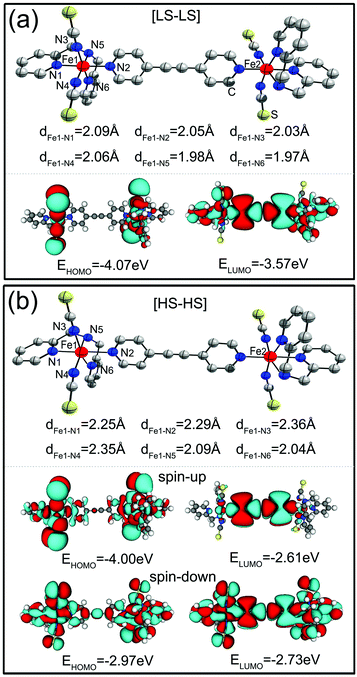 | ||
| Fig. 1 The optimized structures and spatial distribution of the HOMO and LUMO of SCO magnet Fe2 complexes, (a) for the [LS–LS], and (b) for the [HS–HS] spin-pair configuration. | ||
Moreover, we find that the spatial distribution and the energy positions of the frontier orbitals are dramatically different for two different spin-pair configurations. The bottom panels of Fig. 1(a) and (b) present the spatial profiles of the highest occupied molecular orbital (HOMO) and the lowest unoccupied molecular orbital (LUMO) of the SCO magnet Fe2 complexes with the [LS–LS] and [HS–HS] configurations, respectively. As for the SCO magnet Fe2 with the [LS–LS] configuration, the ground state of this isolated complex is nonmagnetic. The HOMO localizes around the ligands, while the LUMO delocalize over the entire complex, which lies at −4.07 and −3.57 eV, respectively. It is clear that for the [HS–HS] configuration, as shown in Fig. 1(b), the SCO magnet Fe2 complex is spin-polarized and two spin channels display different features. The energy gap of the spin-up electrons is about 1.39 eV, which is remarkably larger than the gap of the spin-down electrons (0.24 eV). The HOMO and LUMO of the spin-down electrons located at −2.97 and −2.73 eV are delocalized over the entire complex, while the spin-up HOMO localizes around the ligands and the LUMO localizes around the central region, which are located at −4.00 and −2.61 eV, respectively. These observed remarkable differences in the geometric and electronic structures of SCO magnet Fe2 complexes with different spin-pair configurations suggest that they are possible candidates for designing molecular spintronic devices with interesting transport behavior.
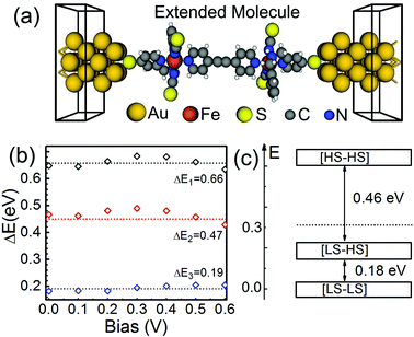
Before investigating the transport properties of SCO magnet Fe2 junctions, as shown in Fig. 2(a), we turned to explore an effective method to realize the spin transition from the [LS–LS] to [HS–HS] configuration in SCO magnet Fe2 complexes, since many experimental and theoretical investigations have revealed that under various external stimuli, such as temperature, light, pressure, magnetic or electric fields, SCO complexes can be switched between two different spin-pair cases.14 Firstly, we calculate the influence of an electric field (arising from the applied bias voltage between the left and right electrodes) on the relative total energies of the molecular junctions with three different spin-pair configurations. Here, ΔE1, ΔE2, and ΔE3 are defined as the averaged total energy difference between [HS–HS] and [LS–LS], [HS–HS] and [LS–HS], and [LS–HS] and [LS–LS] configurations, respectively. We find the influence of an electric field on the relative total energy differences to be relatively small. As shown in Fig. 2(b), in the bias voltage range of [0, 0.6] V, ΔE1, ΔE2, and ΔE3 are predicted to be about 0.66, 0.47, and 0.19 eV, respectively, and all of them vary within 0.05 eV. For example, a bias voltage of 0.6 V just modifies ΔE1, ΔE2, and ΔE3 only about 0.026, 0.042, and 0.015 eV, respectively. These observations imply that an electric field in these examined molecular junctions cannot directly induce the spin transition in SCO magnet Fe2 complexes, although for electronic applications it is more preferable to achieve a spin crossover transition purely by applying an electric field.18 Note that the spin crossover transition by means of an electric field can be achieved for Fe-based single-molecule magnets and Co-based valence tautomeric compounds.21,24
From these calculated total energies for the SCO magnet Fe2 molecular junctions, we find that the mixed [LS–HS] one falls in the energy gap between the [LS–LS] and [HS–HS] configurations, as shown in Fig. 2(c). According to the phenomenological model,34 its position plays a relatively important role in the shaping of the spin transition. To have a two-step spin transition, the relative energy of the SCO magnet Fe2 complex with the [LS–HS] configuration must be lower than the halfway point of the energy gap between the [LS–LS] and [HS–HS] configurations. The averaged total energy between the [LS–LS] and [HS–HS] configurations is predicted to be about 0.32 eV, which is slightly higher than that of the relative energy (0.18 eV) of the [LS–HS] case. This observation agrees well with the experimental observation,36 which means that the SCO magnet Fe2 complexes should display two-step transitions. Clearly, as for the SCO magnet Fe2, our calculated results confirm the phenomenological model.34
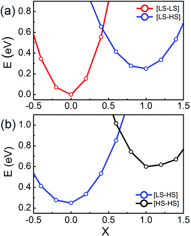
To estimate the energy barriers of the two-step spin transitions of SCO magnet Fe2 complexes, we calculate the total energies of these isolated SCO magnet Fe2 complexes as a function of the reaction coordinates (X), and plot them in Fig. 3(a) and (b). As for the spin transition between the [LS–LS] and [LS–HS] configurations, as shown in Fig. 3(a), X is interpolated between the [LS–LS] (X = 0) and the [LS–HS] (X = 1) geometry for the two different spin-pair configurations. Here, the reaction coordinate projected out of the Hessian matrix is defined as the difference in the local Fe–N distances via normal mode analysis. As expected, Fig. 3(a) clearly shows that the ground state of SCO magnet Fe2 complexes is low spin, corresponding to the [LS–LS] spin-pair configuration. As X increases, originating from the weakening of the local FeN6 ligand field, there is a transition from the [LS–LS] to [LS–HS] for X ∼ 0.42, and the transition barrier is predicted to be about 0.61 eV, while for the spin transition between the [LS–HS] and [HS–HS] configurations, the transition barrier is about 0.93 eV at X ∼ 0.7, as shown in Fig. 3(b). The two transition barriers have relatively large values, implying that the two-step transitions, from the [LS–LS] to [HS–HS] via a plateau [LS–HS] configuration, can be triggered by external stimuli, i.e. temperature or light. Such transitions are accompanied by the geometrical structure modifications, which, at the same time, alter the local FeN6 crystal field strength.36 That is to say, the two-step spin transitions of the Fe2 complexes can be realized by changing the metal-to-ligand bond distances via external stimuli. Then the weak and strong FeN6 crystal fields correspond to the Fe(II) magnetic bistability of the SCO Fe2 complex with the [HS–HS] and [LS–LS] spin-pair configurations, respectively.
Since the exact anchoring configuration of molecular devices in experiments has been a ‘blackbox’ so far, here, we propose several SCO magnet Fe2 complex junctions with different anchoring configurations to explore their transport properties. For example, to model the molecular junction with one more different anchoring group, the SCO magnet Fe2 complexes with the [HS–HS] and [LS–LS] configurations are sandwiched between two Au(100) nanoelectrodes via both thiol and thiocyanato end groups. Fig. S2† shows the proposed molecular junction and the corresponding zero-bias transmission curves. To model the same electrode material with different crystal surfaces and to simulate the SCO magnet Fe2 monolayer case, Fig. S3 and S4† present the calculated results of one SCO magnet Fe2 complex sandwiched between two periodic Au(111) electrodes using 6 × 6 supercells and two SCO magnet Fe2 complexes connected to two periodic Au(100) electrodes using 8 × 8 supercells, respectively. Note that such an anchoring configuration of the SCO magnet Fe2 complexes sandwiched between two Au electrodes via thiol groups is commonly adopted in molecular electronics, although the nature of the Au–S bond and the reacting species involved in the connections need careful check.45
Here, as examples, SCO magnet Fe2 complexes with different spin-pair configurations are sandwiched between two Au(100) nanoelectrodes. Through calculating the adsorption energies, we find that the SCO magnet Fe2 complex prefers to adsorb on the hollow sites of Au(100) surface via Au–S bonds, as shown in Fig. 2(a). The proposed two-probe systems can be divided into three parts, including the left and right electrodes, and the central extended molecule containing the sandwiched SCO magnet Fe2 and two and three surface layers of the left and right electrodes, respectively, where all the screening effects are included into the contact region, and charge distribution in the electrodes is the same as that of the bulk phase. Here, the Au–S distance is fixed to be about 2.59 Å, which is close to the adopted value in the previous investigations.46 Note that the geometric and electronic structures of SCO magnet Fe2 complexes are slightly disturbed by the Au(100) electrodes. The magnetic moment of the SCO magnet Fe2 junction with the [HS–HS] configuration is predicted to be about 8.4μB. The calculated partial density of states of Fe 3d orbitals, as shown in Fig. S5, implies that the HS Fe cation still has the t2g4eg2-like electron configuration.
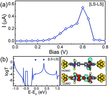
Firstly, we examine the energetically preferred structure of the SCO magnet Fe2 complex, namely the complex that has the [LS–LS] configuration, which corresponds to the low-temperature structure observed in experiments.36 The SCO magnet Fe2 junction is nonmagnetic since both local strong FeN6 crystal fields ensure spin-pair states (two singlets, S = 0). The calculated spin-restricted I–V curve is shown in Fig. 4(a). Here, at each bias voltage, the current is determined self-consistently under the non-equilibrium conditions. It is clear that the I–V curve displays a nonlinear feature and an obvious NDR effect. With increasing bias voltage, the maximum current is about 0.54 μA at the peak position (Vbias = 0.6 V), while the current reaches its minimum value (0.005 μA) at the valley site (Vbias = 0.8 V), which leads to a large peak-valley rate (PVR) of about 100. To explore the nature of the transport behavior of SCO magnet Fe2 complex with the [LS–LS] configuration, the zero-bias transmission function and the local density of states (LDOS) are plotted in Fig. 4(b). Here, two upside-down triangles stand for the perturbed HOMO and LUMO due to the presence of the Au(100) electrodes. Clearly, comparing with the spatial distribution of the HOMO and LUMO of the isolated SCO magnet Fe2 complexes, as shown in Fig. 1, the significant transmission peak at 0.35 eV is mainly contributed by the perturbed LUMO, which is delocalized over the whole complex. Due to the localization, the perturbed HOMO does not lead to a transmission peak at all. The energy separation between the perturbed HOMO and LUMO is about 0.4 eV, which is slightly less than that of the energy space (0.5 eV) between the HOMO and LUMO of the isolated SCO magnet Fe2 with the [LS–LS] configuration. As for the mechanism of NDR behavior, we will address it later.
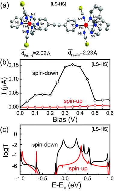
As we discussed above, the SCO magnet Fe2 complex with the mixed [LS–HS] configuration is the intermediate structure for the two-step spin transitions, as shown in Fig. 5(a), which mixes the geometric and electronic structures of the [LS–LS] and [HS–HS] spin-pair configurations. In this case, one of the two Fe(II) has the S = 2 spin state, while the other Fe(II) has the S = 0 spin state. That is to say, the SCO magnet Fe2 complex with the [LS–HS] configuration is spin-polarized. The spin-resolved I–V curves and the zero-bias transmission spectra are calculated and presented in Fig. 5(b) and (c), respectively. Under small bias voltages, the conductance of the SCO magnet Fe2 complex with the [LS–HS] configuration mainly transports through the spin-down electrons. The transmission coefficients of the spin-down electrons around the Fermi level are larger than that of the spin-up electrons, which results in an obvious spin-filtering effect within a certain bias range, i.e. [−0.1, 0.4] V. Moreover, the NDR behavior appears again. The maximum and minimum I↓ is about 0.16 and 0.02 μA, which is located at 0.35 and 0.5 V, respectively. Note that the current through the SCO magnet Fe2 complex with the [LS–HS] configuration is slightly less than that of the [LS–LS] case.
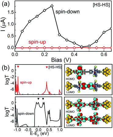
Finally, we turn to explore the transport properties of the SCO magnet Fe2 complex with the [HS–HS] configuration, in which two Fe atoms are located in the weak FeN6 crystal fields due to the long Fe–N separations. The high-spin state of two Fe(II) in this case is characterized by S = 2. This results in the magnetic moment of the SCO magnet Fe2 complex with the [HS–HS] configuration of about 8μB. Fig. 6(a) shows the spin-resolved I–V curves. Here, the red and black lines stand for the current through the spin-up and spin-down electrons, respectively. The following features are observed.
(i) The current through the SCO magnet Fe2 complex with the [HS–HS] configuration is significantly larger than those of the [LS–LS] and [LS–HS] cases. For example, at a bias voltage of 0.25 V, the current through the SCO magnet Fe2 complexes with the [HS–HS], [LS–HS], and [LS–LS] spin-pair configurations is predicted to be about 1.77, 0.09, and 0.006 μA, respectively. That is to say, the former is about two orders larger than the latter two cases.
(ii) As shown in Fig. 6(a), the obvious spin-filtering effect is observed for the SCO magnet Fe2 complex with the [HS–HS] configuration. At a bias voltage of 0.4 V, the calculated current is predicted to be about 3 × 10⁻⁵ and 0.20 μA for the spin-up and spin-down electrons, respectively. The current difference between two spin channels under different bias voltages can be quantified by the ratio of current defined as R(V) = I↓/I↑. The calculated R varies from 6500 to 32![[thin space (1/6-em)]](https://www.rsc.org/images/entities/char_2009.gif) 000 in the bias range of [0.1, 0.4] V. This conductivity dominated by the spin-down electrons has been observed in many magnetic molecules, i.e. ironcyclooctatetraene (Fe-COT) clusters and iron phthalocyanine (FePc).47,48
000 in the bias range of [0.1, 0.4] V. This conductivity dominated by the spin-down electrons has been observed in many magnetic molecules, i.e. ironcyclooctatetraene (Fe-COT) clusters and iron phthalocyanine (FePc).47,48
(iii) At the same time, the NDR phenomenon is observed for the SCO magnet Fe2 junction with the [HS–HS] configuration. When the bias voltage is swept forward to 0.7 V from zero, the I↓ initially increases linearly to about 1.77 μA at 0.25 V. Then, upon approaching to 0.45 V, the I↓ drops to 0.04 μA. This results in a significant NDR behavior with a peak-to-valley ratio of about 25, which is readily measurable in experiments.
(iv) Clearly, a dual functionality, nearly perfect spin-filtering effect and obvious NDR, are integrated into the SCO magnet Fe2 junction with the [HS–HS] configuration. Of course, this remarkable coexistence of the spin-filtering effect and NDR in the SCO magnet Fe2 junction highlights its promising potential for molecular electronic applications, i.e. fast switch devices and logic gates.
To understand the nature of the observed spin filter effect in SCO magnet Fe2 complex with the [HS–HS] configuration, it is useful to look into the spin-polarized zero-bias transmission curves and the spatial distributions of the perturbed HOMO and LUMO, as shown in Fig. 6(b), in which the filled upside-down triangles stand for molecular projected self-consistent Hamiltonian states. It is clear that the transmission spectra of the SCO magnet Fe2 complex for two spin channels display remarkably different behaviors around the Fermi level. The transmission coefficients of the spin-up channel are quite small in the energy region from −0.80 to 0.10 eV. Two sharp and low transmission peaks are located at −0.95 and 0.35 eV, which is contributed by the localized HOMO and LUMO, respectively, as shown in the right panel of Fig. 6(b), while for the spin-down electrons, the delocalized HOMO and LUMO provide the near perfect conductance channels through the molecular junction, which lead to the transmission coefficients at −0.10 and 0.27 eV close to 1G0 (G0 denotes the quantum constant and equals to e2/h). The distinct difference of transmission spectrum between two spin channels can be evaluated with spin filter efficiency, SFE, defined as (T↑ − T↓)/(T↑ + T↓), at the Fermi level. Here, T↑ and T↓ stand for the transmission coefficient of the spin-up and spin-down electrons, predicted to be 1 × 10⁻⁵ and 0.87G0 at the Fermi level, respectively. The calculated SFE at zero-bias is 99.9%, which indicates that conductance through the SCO magnet Fe2 complex with the [HS–HS] configuration is mainly governed by the spin-down electrons.
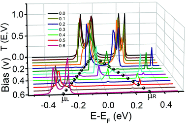
To elucidate the NDR mechanism for SCO magnet Fe2 with the [HS–HS] configuration, we calculate the bias-dependent transmission spectra since their shape and position will change under the applied bias voltage. Fig. 7 shows the transmission spectra in the bias voltage range [0.0, 0.6] V for the spin-down electrons. It is clear that the values of the transmission coefficient change dramatically under the applied bias. With gradually increasing applied bias voltage, two transmission peaks around the Fermi level contributed by the HOMO and LUMO, which gives the dominant contribution to the current through the SCO magnet Fe2, fuse into a transmission peak at 0.15 V. Then it gradually becomes narrow and small, and disappears at about 0.45 V. The current through the sandwiched complex is determined by the integral area under the transmission curve with the bias window. When the bias voltage is less than 0.25 V, there is a relatively large integral area due to the transmission peaks around the Fermi level contributed by the HOMO and LUMO. The current increases with increasing bias voltage. When the applied voltage continuously increases, the fused transmission peak becomes narrow and small, and results in the reduction of the current. So the NDR behavior is observed. The I↓ initially increases, and reaches its maximum (1.77 μA) at 0.25 V. Then it decreases and reaches its minimum (0.043 μA) at 0.45 V. Such a bias-dependent transmission induced NDR behavior has been observed in other molecules, i.e. phenalenyl and four-coordinate Fe complex.49,50
4. Conclusions
In summary, based on DFT calculations combined with the non-equilibrium Green's function technique, we explored the electronic and transport properties of SCO magnet Fe2 complexes with the [LS–LS], [LS–HS] and [HS–HS] spin-pair configurations. We clearly reveal that two-step spin transitions in SCO magnet Fe2 complexes can be achieved by external stimuli, i.e. temperature or light, which agrees well with previous experimental observations and confirms the previous phenomenological model. The SCO magnet Fe2 junction with the [HS–HS] configuration has high spin-filtering efficiency and obvious NDR phenomenon. Under a small bias voltage, the current through the [HS–HS] SCO magnet Fe2 complex is mainly contributed by the spin-down electrons, which results in a nearly perfect spin-filtering effect. The observed NDR phenomenon originates from the bias-dependent transmissions. Theoretical findings suggest that SCO Fe2 complexes hold great promising applications in molecular electronic devices.Acknowledgements
This work was partially supported by the National Key Basic Research Program (no. 2011CB921400 and 2014CB921101), by the Strategic Priority Research Program (B) of the CAS (no. XDB01020000), by the National Natural Science Foundation of China (no. 21273208 and 21473168), by the Anhui Provincial Natural Science Foundation (no. 1408085QB26), and by the Innovative Program of Development Foundation of Hefei Center for Physical Science and Technology. Computational resources have been provided by CAS, Shanghai and USTC Supercomputer Centers.References
- S. A. Wolf, D. D. Awschalom, R. A. Buhrman, J. M. Daughton, S. von Molnár, M. L. Roukes, A. Y. Chtchelkanova and D. M. Treger, Science, 2000, 294, 1488 CrossRef PubMed.
- A. R. Rocha, V. M. García-Suárez, S. Bailey, C. J. Lambert, J. Ferrer and S. Sanvito, Nat. Mater., 2005, 4, 335 CrossRef CAS PubMed.
- S. Sanvito, Chem. Soc. Rev., 2011, 40, 3336 RSC.
- S. D. Jiang, K. Goß, C. Cervetti and L. Bogani, Sci. China: Chem., 2012, 55, 867 CrossRef CAS.
- B. Lapo and W. Wolfgang, Nat. Mater., 2008, 7, 179 CrossRef PubMed.
- J. Lehmann, A. Gaita-Ariño, E. Coronado and D. Loss, J. Mater. Chem., 2009, 19, 1672 RSC.
- J. M. Clemente-Juan, E. Coronado and A. G.-A. No, Chem. Soc. Rev., 2012, 41, 7464 RSC.
- Z. L. Yi, X. Shen, L. L. Sun, Z. Y. Shen, S. M. Hou and S. Sanvito, ACS Nano, 2010, 4, 2274 CrossRef CAS PubMed.
- A. Candini, S. Klyatskaya, M. Ruben, W. Wernsdorfer and M. Affronte, Nano Lett., 2011, 11, 2634 CrossRef CAS PubMed.
- S. M. Avdoshenko, I. N. Ioffe, G. Cuniberti, L. Dunsch and A. A. Popov, ACS Nano, 2011, 5, 9939 CrossRef CAS PubMed.
- Y. H. Zhou, J. Zeng, L. M. Tang, K. Q. Chen and H. P. Wu, Org. Electron., 2013, 14, 2940 CrossRef CAS.
- M. G. Zeng, L. Shen, Y. Q. Cai, Z. D. Sha and Y. P. Feng, Appl. Phys. Lett., 2010, 96, 042104 CrossRef.
- R. R. Nair, I.-L. Tsai, M. Sepioni, O. Lehtinen, J. Keinonen, A. V. Krasheninnikov, A. H. C. Neto, M. I. Katsnelson, A. K. Geim and I. V. Grigorieva, Nat. Commun., 2013, 4, 2010 CAS.
- A. Bousseksou, G. Molnár, L. Salmon and W. Nicolazzi, Chem. Soc. Rev., 2011, 40, 3313 RSC.
- T. Miyamachi, M. Gruber, V. Davesne, M. Bowen, S. Boukari, L. Joly, F. Scheurer, G. Rogez, T. K. Yamada, P. Ohresser, E. Beaurepaire and W. Wulfhekel, Nat. Commun., 2012, 3, 938 CrossRef PubMed.
- P. Gütlich, V. Ksenofontov and A. B. Gaspar, Coord. Chem. Rev., 2005, 249, 1811 CrossRef.
- S. Ohkoshi, K. Imoto, Y. Tsunobuchi, S. Takano and H. Tokoro, Nat. Chem., 2011, 3, 564 CrossRef CAS PubMed.
- H. Hao, X. H. Zheng, L. L. Song, R. N. Wang and Z. Zeng, Phys. Rev. Lett., 2012, 108, 017202 CrossRef PubMed.
- B. Warner, J. C. Oberg, T. G. Gill, F. E. Hallak, C. F. Hirjibehedin, M. Serri, S. Heutz, M. Arrio, P. Sainctavit, M. Mannini, G. Poneti, R. Sessoli and P. Rosa, J. Phys. Chem. Lett., 2013, 4, 1546 CrossRef CAS PubMed.
- R. Bertoni, M. Cammarata, M. Lorenc, S. F. Matar, J. F. Létard, H. T. Lemke and E. Collet, Acc. Chem. Res., 2015, 48, 774 CrossRef CAS PubMed.
- S. Hayami, Y. Komatsu, T. Shimizu, H. Kamihata and Y. H. Lee, Coord. Chem. Rev., 2011, 255, 1981 CrossRef CAS.
- E. Cremades, C. D. Pemmaraju, S. Sanvito and E. Ruiz, Nanoscale, 2013, 5, 4751 RSC.
- L. Cambi and L. Szegö, Ber. Dtsch. Chem. Ges., 1931, 64, 2591 CrossRef.
- P. Gütlich, Y. Garcia and H. A. Goodwin, Chem. Soc. Rev., 2000, 29, 419 RSC.
- M. Nihei, T. Shiga, Y. Maeda and H. Oshio, Coord. Chem. Rev., 2007, 251, 2606 CrossRef CAS.
- D. Aravena and E. Ruiz, J. Am. Chem. Soc., 2012, 134, 777 CrossRef CAS PubMed.
- E. Ruiz, Phys. Chem. Chem. Phys., 2014, 16, 14 RSC.
- H. Phan, S. M. Benjamin, E. Steven, J. S. Brooks and M. Shatruk, Angew. Chem., Int. Ed., 2015, 127, 837 CrossRef.
- W. K. Zhang and K. J. Gaffney, Acc. Chem. Res., 2015, 48, 1140 CrossRef CAS PubMed.
- A. B. Gaspar, M. C. M. Noz and J. A. Real, J. Mater. Chem., 2006, 16, 2522 RSC.
- J. J. M. Amoore, S. M. Neville, B. Moubaraki, S. S. Iremonger, K. S. Murray, J. Létard and C. J. Kepert, Chem. – Eur. J., 2010, 16, 1973 CrossRef CAS PubMed.
- R. Kulmaczewski, J. Olguín, J. A. Kitchen, H. L. C. Feltham, G. N. L. Jameson, J. L. Tallon and S. Brooker, J. Am. Chem. Soc., 2014, 136, 878 CrossRef CAS PubMed.
- P. Maldonado, S. Kanungo, T. S. Dasgupta and P. M. Oppeneer, Phys. Rev. B: Condens. Matter, 2013, 88, 020408(R) CrossRef.
- S. Zein and S. A. Borshch, J. Am. Chem. Soc., 2005, 127, 16197 CrossRef CAS PubMed.
- G. S. Matouzenko, E. Jeanneau, A. Y. Verat and A. Bousseksou, Dalton Trans., 2011, 40, 9608 RSC.
- G. S. Matouzenko, E. Jeanneau, A. Y. Verat and Y. Gaetano, Eur. J. Inorg. Chem., 2012, 6, 969 CrossRef.
- A. Pronschinske, R. C. Bruce, G. Lewis, Y. F. Chen, A. Calzolari, M. Buongiorno-Nardelli, D. A. Shultz, W. You and D. B. Dougherty, Chem. Commun., 2013, 49, 10446 RSC.
- G. Poneti, L. Poggini, M. Mannini, B. Cortigiani, L. Sorace, E. Otero, P. Sainctavit, A. Magnani, R. Sessoli and A. Dei, Chem. Sci., 2015, 6, 2268 RSC.
- E. J. Devid, P. N. Martinho, M. V. Kamalakar, I.
![[S with combining breve]](https://www.rsc.org/images/entities/char_0053_0306.gif) alitro
alitro![[s with combining breve]](https://www.rsc.org/images/entities/char_0073_0306.gif) , Ú. Prendergast, J. Dayen, V. Meded, T. Lemma, R. González-Prieto, F. Evers, T. E. Keyes, M. Ruben, B. Doudin and S. J. van der Molen, ACS Nano, 2015, 4, 4496 CrossRef PubMed.
, Ú. Prendergast, J. Dayen, V. Meded, T. Lemma, R. González-Prieto, F. Evers, T. E. Keyes, M. Ruben, B. Doudin and S. J. van der Molen, ACS Nano, 2015, 4, 4496 CrossRef PubMed. - J. Taylor, H. Guo and J. Wang, Phys. Rev. B: Condens. Matter, 2001, 63, 245407 CrossRef.
- M. Brandbyge, J.-L. Mozos, P. Ordejón, J. Taylor and K. Stokbro, Phys. Rev. B: Condens. Matter, 2002, 65, 165401 CrossRef.
- J. Huang, W. Y. Wang, S. F. Yang, Q. X. Li and J. L. Yang, Nanotechnology, 2012, 23, 255202 CrossRef PubMed.
- J. Huang, W. Y. Wang, Q. X. Li and J. L. Yang, J. Chem. Phys., 2014, 140, 164703 CrossRef PubMed.
- Using the Gaussian09 package, we obtain the optimized geometric structures of free SCO magnet Fe2 isomers by using the Becke three-parameter Lee–Yang–Parr (B3LYP) hybrid functional, which has the potential to ensure a correct order of different spin states for experimental structures of mononuclear spin transition complexes at low and high temperatures. We find that the molecular magnetic moment and the spatial distribution of frontier molecular orbitals are not sensitive to the used functionals, and the hybrid DFT calculations enhance the level spacings.
- A. Bencini, G. Rajaraman, F. Totti and M. Tusa, Superlattices Microstruct., 2009, 46, 4 CrossRef CAS.
- K. Stokbro, J. Taylor, M. Brandbyge, J.-L. Mozos and P. Ordejón, Comput. Mater. Sci., 2003, 27, 151 CrossRef CAS.
- J. Huang, Q. X. Li, K. Xu, H. B. Su and J. L. Yang, J. Phys. Chem. C, 2010, 114, 11946 CAS.
- J. Huang, K. Xu, S. L. Lei, H. B. Su, Q. X. L. S. F. Yang and J. L. Yang, J. Chem. Phys., 2012, 136, 064707 CrossRef PubMed.
- Z. Q. Fan and K. Q. Chen, Appl. Phys. Lett., 2010, 96, 053509 CrossRef.
- P. Zhao, Q. H. Wu, D. S. Liu and G. Chen, J. Chem. Phys., 2014, 140, 044311 CrossRef CAS PubMed.
Footnote |
| † Electronic supplementary information (ESI) available: The spin density of SCO magnet Fe2 complexes, the partial DOS of HS Fe cations, zero-bias transmission curves of SCO magnet Fe2 junctions with different anchoring configurations, and bias-dependent transmission curves of SCO magnet Fe2 complexes with the [LS–LS] and [LS–HS] configurations. See DOI: 10.1039/C5NR05601B |
| This journal is © The Royal Society of Chemistry 2016 |

