Elastic porous carbon material supported sulfur cathodes for Li–S battery design†
Weidong
Xiao
ab,
Liwei
Mi
*a,
Shizhong
Cui
a,
Hongwei
Hou
b and
Weihua
Chen
*b
aCenter for Advanced Materials Research, Zhongyuan University of Technology, Zhengzhou, Henan 450007, P. R. China. E-mail: mlwzzu@163.com
bCollege of Chemistry and Molecular Engineering, Zhengzhou University, Zhengzhou, Henan 450001, P. R. China. E-mail: chenweih@zzu.edu.cn
First published on 23rd November 2015
Abstract
In this work, we present a three-dimensional elastic carbon foam as a current collector and freestanding electrode for Li–S batteries. A sulfur content of approximately 43.93% which was based on the weight of cathode was achieved. The non-additive S cathode with good elasticity shows a first discharge specific capacity of 893 mA h g−1 and a specific capacity of 544 mA h g−1 after 30 cycles at moderate rates. A coulombic efficiency of 98% over 100 cycles is achieved.
In recent years, new electric vehicles have attracted increasing attention because of the urgent need for energy conservation and the enhancement of environmental awareness. Therefore, efficient energy storage has become a top priority.1–3 Among the various types of rechargeable batteries, the lithium–sulfur (Li–S) battery shows great promise because of its high theoretical specific capacity (1675 mA h g−1) and energy density (2600 W h kg−1).4,5 In addition, sulfur is abundant on earth, easily available, and environmentally friendly. However, the practical application of Li–S batteries has encountered a series of obstacles, such as low active material utilization and poor cycle life.3,4,6 In fact, the low electrical conductivity of sulfur (5 × 10⁻³⁰ S cm−1 at 25 °C), the solubility of intermediate lithium polysulfide (Li2Sn, n > 2), and the large volume change (up to 80%) mainly lead to the low utilization of active materials and poor coulombic efficiency.7,8 One of the most important strategies in solving the aforementioned issues is to effectively combine sulfur with electronically conductive additives.9 In recent years, various efforts have been devoted to the development of Li–S batteries by encapsulating or mixing sulfur with conducting materials, including carbon black,10,11 porous carbon,12,13 hollow carbon spheres,14,15 cnts,16,17 graphene(oxide)18,19 and conducting polymers.8,20 Other novel approaches include the application of nanoscale sulfur21,22 and Li2S particles23–25 as active materials. Meanwhile, the efforts toward interlayers have achieved significantly positive results.26–28
The portable, flexible and wearable electronics that have emerged in recent years depend largely on flexible battery materials.7,29,30 Thus, extensive efforts have been devoted to the fabrication of flexible materials for energy storage.7,29,31–33
To address the need for flexible batteries, we choose a novel elastic carbon material to construct battery cathodes. To our best knowledge, this is the first time that a three dimensional flexible carbon foam is being used in lithium sulfur batteries. Specifically, we propose a three-dimensional carbon foam material as a freestanding electrode without a binder. Additionally, the carbon foam with a low density less than 10 mg cm−3 is more lightweight than other carbon materials. So it has high potential to enhance the energy density. Also, the carbon foam as a whole for sulfur carriers could facilitate electron transfer. Furthermore, the porous carbon foam with excellent elasticity has inherent advantages for structure flexible batteries. So the commercial melamine foam-derived carbon foam has great potential for the industrial fabrication of lithium sulfur batteries on large scale.
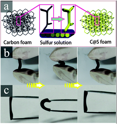
The carbon foam (C foam) was developed by directly carbonizing melamine foam (MF) resin. The main component of MF is formaldehyde–melamine, which is a commercially available environmentally friendly polymer foam material.31 The N2 adsorption–desorption isotherm of the C foam was determined (Fig. S1, ESI†), and it shows a Brunauer–Emmett–Teller (BET) specific surface area of 52.96 m2 g−1 and a large pore volume of 2.03 cm3 g−1. The C foam-coated sulfur material (C@S foam) was fabricated through a facial solution immersion method (Fig. 1a), and the loading of sulfur was approximately 1.2 mg. Good elasticity was observed in both the C foam and the C@S foam (Fig. 1b and c).
 | ||
| Fig. 1 (a) Schematic illustration of the fabrication of the C@S foam cathode, and digital photos of the flexible elasticity of (b) the C foam and (c) C@S foam. | ||
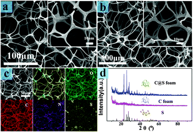
To further examine the structure and components of the C foam and C@S foam, we performed scanning electron microscopy and energy dispersive spectrometer mapping. As shown in Fig. 2a, the foam demonstrated a high slenderness ratio in the interconnection network architecture; this ratio determined the excellent elasticity of the foam.31 The structure of the C foam was almost the same as that of the raw foam materials (Fig. S2, ESI†). The sulfur cathode prepared through a simple solution impregnation method showed the same structure as that of the C foam. The elastic framework not only offered shelter for sulfur but also prevented architecture deterioration resulting from volume expansion. Also, the interconnected framework could enhance the contact probability between the active sulfur and the electrolyte, thus potentially improving the use of active sulfur to some extent.34 The thickness of the sulfur deposited on the C foam was approximately 300 nm (Fig. S3, ESI†). The distance between adjacent skeletons was approximately 50 μm before battery assembling. However, the skeletons became closer with an integral structure after battery assembling (Fig. S4, ESI†). The result of reducing the distance is a short diffusion distance of polysulfides. The C foam is composed of carbon, nitrogen, and oxygen. Part of the sulfur block was observed in the mapping pattern, as well as in the SEM pattern (Fig. S3, ESI†). This result is consistent with low active material utilization. The X-ray diffraction (XRD) of the C foam with and without sulfur (Fig. 2) proved the good combination of sulfur and the C foam. The characteristic peaks of the orthorhombic phase of sulfur (JCPSD no. 08-0247) were observed in the characteristic XRD patterns of the C@S foam. This result indicated the existence of crystalline sulfur.
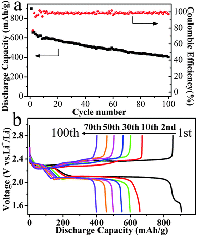
Fig. 3 shows the galvanostatic charge–discharge curves of the Li–S battery with the C@S foam cathode at a rate of 0.2 C. As shown in Fig. 3a, the first two discharge specific capacities reached 893 mA h g−1 and 649 mA h g−1. The low discharge specific capacity is associated with the formation of block sulfur in the process of sulfur deposition in this work. The block sulfur with low conductivity hinders the battery reaction largely. So the block sulfur turns into die sulfur in batteries, which has a small contribution to discharge capacity. In the absence of a binder and coating, the sulfur deposited onto the surface of the carbon foam skeleton is inevitably lost into the electrolyte during the process of dissolution and deposition repeatedly. A coulombic efficiency approaching 98% was achieved after 100 cycles. The superior coulombic efficiency achieved in the galvanostatic charge–discharge curves may benefit from the addition of LiNO335 and the special cathode material. On the one hand, the stable passivation layer formed by the oxidation of LiNO3 can efficiently slow down the reduction of the polysulfide species at the lithium surface.36 On the other hand, the good flexibility of the cathode material can sustain the volume change during cycles. Two discharge plateaus were observed at 2.31 and 2.06 V, which corresponded to the reduction from S to S42− and from S42− to S2−, respectively.5 As the battery voltage approached 2.6 V in the charging process, the vertical voltage increased, thus indicating that cells employing C@S cathodes can be completely charged without a significant shuttling effect.37 However, the small knee point at 1.70 V in the first discharge curve may be associated with the irreversible reduction of LiNO3, which only appeared in the first discharge curve.38
 | ||
| Fig. 3 The electrochemical performance of the Li–S battery: (a) the cycle stability and coulombic efficiency, and (b) the charge and discharge specific capacities at different cycles. | ||
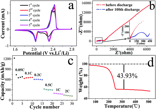
To investigate the charge–discharge behavior of the C@S cathodes, we conducted cyclic voltammetry (CV) measurements on the battery in a voltage range of 2.8 V to 1.6 V. As shown in Fig. 4a, the two main cathodic peaks at 2.31 and 2.06 V of the reduction curves are consistent with the two-step reduction of S, and the result corresponds to the charge–discharge curves. The difference of the cathodic peaks in the first and other cycles was ascribed to the rearrangement of active sulfur from its original positions to more energetically stable sites.28 In addition, one oxidation peak with a small shoulder peak was observed in the CV curves in the first five cycles. This result indicated the oxidation of short-chain polysulfides to elemental sulfur or long-chain polysulfides.39 The lack of obvious potential shifts in the other cycles confirmed the excellent reversibility and stability of the porous C@S foam cathode.40
Fig. 4b shows typical Nyquist plots of the Li–S battery with the C@S cathode before and after 100 cycles in charged states. The Nyquist curves before the cycles were composed of one semicircle and a long inclined line, which represented the blocking character of the non-lithiated electrode.41 After 100 cycles, the Nyquist curves comprised two depressed semicircles at the high frequency and middle frequency regions and a short inclined line in the low frequency regions. The semicircle at the middle frequency region reflected the charge transfer resistance and its relative capacitance at the phase interface.42 In comparison with the AC impedance before the cycles, the semicircle after the cycles decreased obviously, which is in agreement with the rearrangement of sulfur described above. In addition, the semicircle in the high frequency range was related to the formation of a solid electrolyte interface.41 The incline in the low frequency region was related to the Warburg impedance.43 The rate performance of the C@S foam battery at current densities ranging from 0.05 C to 2 C is shown in Fig. 4c. The C@S foam battery achieved a good performance rate at low current density and serious capacity decay at high current density. This result can be attributed to the high charge-transfer resistance and mass transport resistance in the cathode, which is a control step in the lower voltage plateau. Thermogravimetric analysis of the C@S foam revealed a sulfur content of approximately 43.93% which was based on the weight of the cathode.
In summary, we developed a simple and scalable C foam as a freestanding cathode for Li–S batteries. This material has shown good electrochemical performance. Therefore, we demonstrated the feasibility of C foam-supported sulfur cathode batteries without any conductive additive. The three-dimensional C foam with excellent flexibility presents great promise as an electrode material for emerging portable, flexible, and wearable electronics. Moreover, the advantages of the facile fabrication method and the commercially available material make them alternatives for the emerging flexible battery market. In addition, the method of fabrication of our cathode material will be suitable for large scale industrial production.
Experimental
The porous carbon foam was fabricated by direct carbonization of melamine foam at 750 °C with a heating rate of 5 °C min−1 under a nitrogen atmosphere and annealing for about 1 h at the final temperature. Then the carbon foam was cut into the desired shapes. The as-prepared carbon foam pieces were dipped into ethanol solution saturated sulfur under ultrasonic treatment for five minutes. Then the foam was transferred into a vacuum oven at 70 °C under vacuum conditions. After repeating the above process several times, the sulfur cathode with an excellent elasticity was obtained.Acknowledgements
This work was supported by the Natural Science Foundation of China (no. 21443003, U1407103), Henan Province (no. 15HASTIT003) and Zhengzhou University (no. 1421316035).Notes and references
- A. Manthiram, Y. Fu, S. H. Chung, C. Zu and Y. S. Su, Chem. Rev., 2014, 114, 11751–11787 CrossRef CAS PubMed.
- P. G. Bruce, S. A. Freunberger, L. J. Hardwick and J. M. Tarascon, Nat. Mater., 2012, 11, 19–29 CrossRef CAS PubMed.
- Y. X. Yin, S. Xin, Y. G. Guo and L. J. Wan, Angew. Chem., Int. Ed., 2013, 52, 13186–13200 CrossRef CAS PubMed.
- X. Liang, C. Hart, Q. Pang, A. Garsuch, T. Weiss and L. F. Nazar, Nat. Commun., 2015, 6, 5682 CrossRef PubMed.
- Y. V. Mikhaylik and J. R. Akridge, J. Electrochem. Soc., 2004, 151, A1969–A1976 CrossRef CAS.
- X. Ji and L. F. Nazar, J. Mater. Chem., 2010, 20, 9821–9826 RSC.
- G. Zhou, L. Li, C. Ma, S. Wang, Y. Shi, N. Koratkar, W. Ren, F. Li and H.-M. Cheng, Nano Energy, 2015, 11, 356–365 CrossRef CAS.
- W. D. Zhou, Y. C. Yu, H. Chen, F. J. DiSalvo and H. D. Abruna, J. Am. Chem. Soc., 2013, 135, 16736–16743 CrossRef CAS PubMed.
- J. Gao and H. D. Abruña, J. Phys. Chem. Lett., 2014, 5, 882–885 CrossRef CAS PubMed.
- B. Zhang, C. Lai, Z. Zhou and X. P. Gao, Electrochim. Acta, 2009, 54, 3708–3713 CrossRef CAS.
- Y.-S. Su and A. Manthiram, Electrochim. Acta, 2012, 77, 272–278 CrossRef CAS.
- K. Yang, Q. M. Gao, Y. L. Tan, W. Q. Tian, L. H. Zhu and C. X. Yang, Microporous Mesoporous Mater., 2015, 204, 235–241 CrossRef CAS.
- P. Strubel, S. Thieme, T. Biemelt, A. Helmer, M. Oschatz, J. Brückner, H. Althues and S. Kaskel, Adv. Funct. Mater., 2015, 25, 287–297 CrossRef CAS.
- Z. B. Wang, S. C. Zhang, L. Zhang, R. X. Lin, X. M. Wu, H. Fang and Y. B. Ren, J. Power Sources, 2014, 248, 337–342 CrossRef CAS.
- G. Q. Ma, Z. Y. Wen, J. Jin, Y. Lu, X. W. Wu, C. Liu and C. H. Chen, RSC Adv., 2014, 4, 21612–21618 RSC.
- Z. Zhang, H. K. Jing, S. Liu, G. R. Li and X. P. Gao, J. Mater. Chem. A, 2015, 3, 6827–6834 CAS.
- Z. Yuan, H. J. Peng, J. Q. Huang, X. Y. Liu, D. W. Wang, X. B. Cheng and Q. Zhang, Adv. Funct. Mater., 2014, 24, 6105–6112 CrossRef CAS.
- X. W. Wang, Z. A. Zhang, Y. H. Qu, Y. Q. Lai and J. Li, J. Power Sources, 2014, 256, 361–368 CrossRef CAS.
- H. F. Li, X. W. Yang, X. M. Wang, M. N. Liu, F. M. Ye, J. Wang, Y. C. Qiu, W. F. Li and Y. G. Zhang, Nano Energy, 2015, 12, 468–475 CrossRef CAS.
- W. Qin, B. D. Fang, S. T. Lu, Z. D. Wang, Y. Chen, X. H. Wu and L. Han, RSC Adv., 2015, 5, 13153–13156 RSC.
- S. Xin, L. Gu, N. H. Zhao, Y. X. Yin, L. J. Zhou, Y. G. Guo and L. J. Wan, J. Am. Chem. Soc., 2012, 134, 18510–18513 CrossRef CAS PubMed.
- J. Zhang, Z. M. Dong, X. L. Wang, X. Y. Zhao, J. P. Tu, Q. M. Su and G. H. Du, J. Power Sources, 2014, 270, 1–8 CrossRef CAS.
- Y. Z. Fu, C. X. Zu and A. Manthiram, J. Am. Chem. Soc., 2013, 135, 18044–18047 CrossRef CAS PubMed.
- L. N. Wang, Y. G. Wang and Y. Y. Xia, Energy Environ. Sci., 2015, 8, 1551 CAS.
- Y. Yang, G. Y. Zheng, S. Misra, J. Nelson, M. F. Toney and Y. Cui, J. Am. Chem. Soc., 2012, 134, 15387–15394 CrossRef CAS PubMed.
- Y. S. Su and A. Manthiram, Nat. Commun., 2012, 3, 1166–1171 CrossRef PubMed.
- G. Q. Ma, Z. Y. Wen, J. Jin, M. F. Wu, X. W. Wu and J. C. Zhang, J. Power Sources, 2014, 267, 542–546 CrossRef CAS.
- Z. Xiao, Z. Yang, L. Wang, H. Nie, M. Zhong, Q. Lai, X. Xu, L. Zhang and S. Huang, Adv. Mater., 2015, 27, 2891–2898 CrossRef CAS PubMed.
- G. Zhou, L. Li, D. W. Wang, X. Y. Shan, S. Pei, F. Li and H. M. Cheng, Adv. Mater., 2015, 27, 641–647 CrossRef CAS PubMed.
- Y. Hu and X. Sun, J. Mater. Chem. A, 2014, 2, 10712–10738 CAS.
- S. Chen, G. He, H. Hu, S. Jin, Y. Zhou, Y. He, S. He, F. Zhao and H. Hou, Energy Environ. Sci., 2013, 6, 2435–2439 CAS.
- G. M. Zhou, Y. B. Zhao and A. Manthiram, Adv. Energy Mater., 2015, 5, 1402263 Search PubMed.
- Y. Zhang, Z. Bakenov, Y. Zhao, A. Konarov, Q. Wang and P. Chen, Ionics, 2013, 20, 803–808 CrossRef.
- S.-H. Chung and A. Manthiram, J. Mater. Chem. A, 2013, 1, 9590–9596 CAS.
- G. Zheng, Y. Yang, J. J. Cha, S. S. Hong and Y. Cui, Nano Lett., 2011, 11, 4462–4467 CrossRef CAS PubMed.
- S. S. Zhang and J. A. Read, J. Power Sources, 2012, 200, 77–82 CrossRef CAS.
- S.-H. Chung and A. Manthiram, Electrochim. Acta, 2013, 107, 569–576 CrossRef CAS.
- S. S. Zhang, J. Electrochem. Soc., 2012, 159, A920–A923 CrossRef CAS.
- N. Jayaprakash, J. Shen, S. S. Moganty, A. Corona and L. A. Archer, Angew. Chem., Int. Ed., 2011, 50, 5904–5908 CrossRef CAS PubMed.
- S. H. Chung and A. Manthiram, Adv. Mater., 2014, 26, 7352–7357 CrossRef CAS PubMed.
- C. Barchasz, J.-C. Leprêtre, F. Alloin and S. Patoux, J. Power Sources, 2012, 199, 322–330 CrossRef CAS.
- Z. Deng, Z. Zhang, Y. Lai, J. Liu, J. Li and Y. Liu, J. Electrochem. Soc., 2013, 160, A553–A558 CrossRef CAS.
- W. Ahn, K.-B. Kim, K.-N. Jung, K.-H. Shin and C.-S. Jinb, J. Power Sources, 2012, 202, 394–399 CrossRef CAS.
Footnote |
| † Electronic supplementary information (ESI) available. See DOI: 10.1039/c5nj02938d |
| This journal is © The Royal Society of Chemistry and the Centre National de la Recherche Scientifique 2016 |


