
Novel supercapacitor materials including OLED emitters†
Seungho
Kim
a,
Kihun
Jang
b,
Beom-Soo Michael
Park
c,
Heejoon
Ahn
b,
Jang Myoun
Ko
d and
Jongwook
Park
*a
aDepartment of Chemistry/Display Research Center, The Catholic University of Korea, Bucheon, 420-743, South Korea. E-mail: hahapark@catholic.ac.kr; Fax: +82-2-2164-4764; Tel: +82-2-2164-4821
bDepartment of Organic and Nano Engineering, Institute of Nano-Science and Technology, Hanyang University, 17 Haengdang-dong, Seongdong-gu, Seoul 133-791, South Korea
cNorthwestern University, 633 Clark Street, Evanston, IL 60208, USA
dDepartment of Chemical Technology, Hanbat National University, Daejeon, 305-719, South Korea
First published on 23rd October 2015
Abstract
This study constitutes the first attempt to use an OLED emitter material as a novel supercapacitor component. In supercapacitor tests, the specific capacitance (33.07 F g−1) of a poly(9-(3-vinyl-phenyl)-anthracene) (PVPA)/multi-walled carbon nanotube (MWCNT) mixture was found to be approximately three times that of the system composed of the MWCNTs alone.
In recent times researchers have devoted much effort to developing and refining energy storage devices such as batteries, supercapacitors, and fuel cells.1–5 Supercapacitors have attracted particular interest because they have higher energy densities than conventional capacitors, higher power densities than batteries, and a long lifetime. These characteristics made supercapacitors to emerge as highly promising devices in electrical vehicles, consumer electronics, memory backup, and military devices. However, for high power applications, supercapacitors have a major disadvantage in possessing much lower energy density compared to that of batteries. As a result, recent effort in supercapacitor development, including this study, has been focused on improving the energy density to make it comparable to that of batteries.
A supercapacitor, or an electrical double layer capacitor (EDLC), is an electrostatic storage device in which electrical energy is stored by separating the charge in a double layer at the interface between the surface of a conductor electrode and an electrolyte solution, as shown Fig. S1 (ESI†).
Carbon-containing materials such as carbon nanotubes (CNTs), graphene, activated carbon, and mesoporous carbon have been studied for use in supercapacitors.6–10 Among them, CNTs are attractive and representative materials for energy storage devices due to their advantageous properties, which include high chemical stability, high aspect ratio, high mechanical strength, and highly activated surface area.11,12 However, despite these properties, the capacitance performance of CNT-based supercapacitors developed to date has been lower than expected.13 As a result, significant attention has been devoted to nanocomposites of multi-walled carbon nanotubes (MWCNTs) and metal oxides due to the excellent properties of each of these materials plus their synergistic effects when used as composite electrode materials for supercapacitors.14–16 However, these systems have the drawbacks that they require complicated and expensive processes involving high temperatures (>400 °C), long preparation time, and expensive metal oxides (RuOx).17–21 Also, Peng et al. reported that the use of a composite of conducting polymers and carbon nanotubes as the supercapacitor electrode material enhanced the charge storage properties of the supercapacitor.22–24 However, in this study, we combine MWCNTs and an organic light emitting diode (OLED) emitter. Considering the mechanism underlying these devices, the key factor determining the performance of supercapacitor electrodes is their behavior in terms of the absorption and desorption of ions in the adjoining electrolyte solution. This behavior could potentially be improved by including within the electrode an organic light emitting diode (OLED) material, since such materials have strong ion stability. The incorporation of an OLED material into a supercapacitor electrode may potentially enhance the properties of the supercapacitor such as its specific capacitance and durability.
In the present work, we examined a novel material system composed of a mixture of CNTs (a representative supercapacitor electrode material) and an OLED emitter.
In our previous study on OLED emitter materials, we synthesized a new blue emitting polymer, poly(9-(3-vinyl-phenyl)-anthracene) (PVPA), as shown in Scheme S1 and Table S1 (ESI†).25 In OLEDs, cationic and anionic species are transported inside the emitter material when a voltage is applied, as shown in Fig. 1. In PVPA, anthracene, a very useful chemical group in commercial blue OLED emitters,26–28 allows the polymer to have a relatively strong ion stability under device operation. For this study, we wondered whether these advantageous properties of PVPA could be exploited by creating a mixture material based on MWCNTs and PVPA to increase the energy density of supercapacitors. Such a mixture material could be prepared via a facile process using low process temperatures (<200 °C). This would constitute a major advantage over the aforementioned nanocomposite mixture systems with MWCNTs and metal oxides.
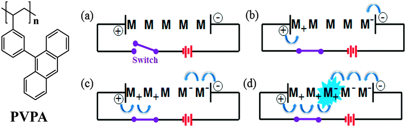 | ||
| Fig. 1 Chemical structures of the synthesized compound and the emission process of an OLED device: (a) 0 V and (b)–(d) according to time under the operating voltage. | ||
The main motivation for this study was to test whether the energy density of a supercapacitor could be enhanced by using a mixture material system comprised of PVPA and MWCNTs. The present work represents the first attempt to use an OLED emitter polymer in conjunction with MWCNTs as a supercapacitor electrode material.
Fig. 1 shows the PVPA and OLED device emission process. Upon selecting an OLED emitter material for use in supercapacitors, we noted similarities between the mechanisms of the supercapacitor and OLED operation. In particular, we noted that OLED emitters are highly stable in the ion state, a property that is also required for supercapacitor applications.29,30Fig. 1 shows a schematic of the OLED emission process of the emitter (M) according to the applied voltage. When the applied voltage is 0 (Fig. 1(a)), the hole and electron carriers are located at the edges of the anode (on the left) and the cathode (on the right), respectively. When a voltage is applied, holes and electrons jump inside the material (Fig. 1(b)), thereby changing the charges on the molecules from neutral to ionic, M+ and M−. As the voltage is increased, M+ and M− species move to the center of the material (Fig. 1(c)). This behavior indicates that the emitter has a suitable carrier mobility for normal device operation. Finally, pairs of cation and anion carriers meet in the central area and recombine to form a recombination center for emission. This recombination center, called an exciton, can emit radiation by shifting electrons from the excited state to the ground state, as shown in Fig. 1(d).31,32 Therefore, for an emitter material to be suitable for OLED applications, it must be stable in the cationic and anionic states and must have appropriate carrier mobility properties. We hypothesized that these properties of OLED emitter materials would make such materials suitable for use in supercapacitors.
A typical EDLC supercapacitor unit cell is comprised of two electrodes that are isolated from electrical contact. Metal foil is used as a current collector to conduct electrical current from each electrode. The electrodes are impregnated with an electrolyte, which allows ionic current to flow between the electrodes. The mechanism of ion absorption and desorption to the electrical double layer contributes to the charge and discharge of the EDLC.
By applying voltage to the facing electrodes, ions are drawn to the surface of the electrical double layer and electricity is charged. Conversely, they move away when discharging electricity. The EDLC charge–discharge processes are shown in Fig. S1 (ESI†).33,34
As shown in Fig. S2 (ESI†), the mixture of MWCNTs and PVPA (1![[thin space (1/6-em)]](https://www.rsc.org/images/entities/char_2009.gif) :0.85 w/w) was prepared and was coated onto a clean SUS (steel use stainless) substrate by blade coating.
:0.85 w/w) was prepared and was coated onto a clean SUS (steel use stainless) substrate by blade coating.
Fig. 2(a) and (b) show surface SEM images of the MWCNT and PVPA/MWCNT films, respectively. The MWCNT film is comprised of a homogeneous collection of worm-like structures with radii less than 40 nm. In the PVPA/MWCNT film, in contrast, a round PVPA cluster with a size of around 100 to 200 nm was observed (center of Fig. 2(b)). To confirm that the cluster consisted of a polymer material, the film was dipped 10 times in methylene chloride, a solvent in which the polymer, but not the MWCNTs, is soluble.
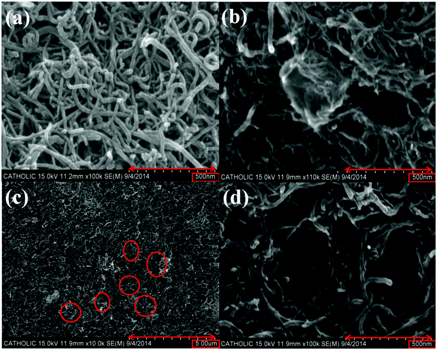 | ||
| Fig. 2 SEM images of (a) MWCNT, (b) PVPA/MWCNT, (c) PVPA/MWCNT after solvent (methylene chloride) washing, and (d) PVPA/MWCNT after solvent (methylene chloride) washing. | ||
Fig. 2(c) and (d) show SEM images of the surface of the solvent-washed film surface at two resolutions. Several holes, with diameters ranging from 100 nm to 200 nm, are observed on the surface. Comparing images of the same surface before and after washing with solvent (Fig. 2(b) and (d)), it is clearly verified that the cluster in Fig. 2(b) has disappeared in Fig. 2(d) and has been replaced by a similar sized hole, indicating that the clusters in the PVPA/MWCNT film were comprised of PVPA.
Fig. 3a and b show the CV curves obtained for MWCNT and PVPA/MWCNT samples in the NaCl electrolyte (1 M water solution), using seven scan rates in the range of 20 to 200 mV s−1. In the CV experiments, a three electrode system including a Ag/AgCl reference electrode was used in order to accurately evaluate the capacitance of the mixture. All of the CV curves showed a marked current response in the potential range of −0.6 V to 0.1 V. As the scan rate was increased from 20 to 200 mV s−1, the current increased because of the faster sweep speed. Comparing the CV curves for the MWCNT and PVPA/MWCNT film systems, it is observed that the current is higher for the PVPA/MWCNT than for the MWCNT film. The energy densities of these systems can be assessed by calculating the specific capacitance (F g−1), which provides a measure of the energy density.
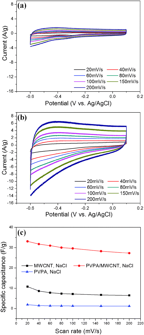 | ||
| Fig. 3 CV curves recorded at various scan rates from 20 to 200 mV s−1 in the NaCl electrolyte: (a) MWCNT, (b) PVPA/MWCNT, and (c) the specific capacitance of PVPA, MWCNT and PVPA/MWCNT according to the scan rate (blue line = PVPA, black line = MWCNT, and red line = PVPA/MWCNT). | ||
In CV curves, the y axis is the current per gram and the area under the CV curve is the electric charge in coulombs, Q. A system with a high energy density will have a large area under the curve. Based on the CV curves, specific capacitance values indicating the energy density were calculated using the following equation.14–16
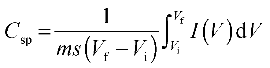 | (1) |
Peng et al. reported a specific capacitance of 50 F g−1 for MWCNTs;35 however, the MWCNT material used in the present work showed a value of 10.79 F g−1.
The specific capacitance values for the films are summarized in Fig. 3c. Remarkably, the PVPA specific capacitance was very low and the PVPA/MWCNT specific capacitance was three times that of the MWCNT sample (10.79 F g−1vs. 33.07 F g−1 at 20 mV s−1). A similar increase was obtained at a scan rate of 200 mV s−1. The marked enhancement of the specific capacitance upon adding PVPA to the MWCNT sample may be due to the adsorption of PVPA to the MWCNTs, as PVPA increases redox current. The specific capacitance values under various electrolytes, including KCl, KOH, and NaOH, were measured and the results are summarized in Table S2 (ESI†). It was found that PVPA also enhanced the specific capacitance under other electrolytes. The higher specific capacitance of the PVPA/MWCNT film can also be explained by an impedance experiment.36–38
Electrochemical impedance spectroscopy is a powerful technique for characterizing the properties of electrode–electrolyte interfaces such as equivalent series resistance and charge resistance. Fig. 4 shows Nyquist plots of the MWCNT and PVPA/MWCNT electrodes over the frequency range from 100 kHz to 0.01 Hz. For both the MWCNT and PVPA/MWCNT electrodes, the equivalent series resistance (Rs; the intercept on the x-axis at the high frequency end) is less than 1.5 Ω. However, the charge transfer resistance (Rct) of the PVPA/MWCNT electrode (2.8 Ω) is smaller than that of the MWCNT electrode (3.8 Ω), indicating enhanced electrical conductivity in the PVPA/MWCNT electrode. The straight line at low frequency in the Nyquist plot is indicative of Warburg impedance, which is related to ion diffusion in a solution under a high speed charging reaction.
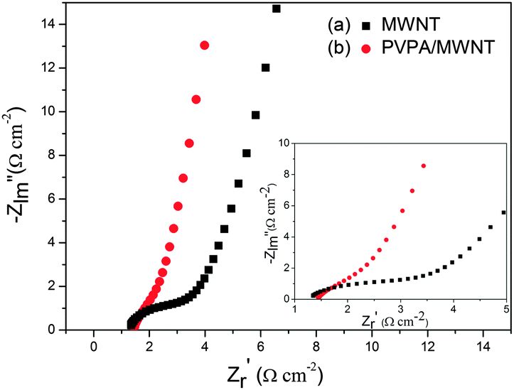 | ||
| Fig. 4 Nyquist plots of MCWNT and PVPA/MCWNT thin films in 1 M NaCl solution between Pt electrodes with an AC voltage amplitude of 10 mV (bias potential: 0 V) and a frequency range of 100 kHz–0.01 Hz; the inset shows the equivalent circuit and expanded plots. | ||
The straight line at low frequency in the Nyquist plot is indicative of Warburg impedance, which is related to ion diffusion in a solution under a high speed charging reaction. The straight line with a high angle (about 80°) observed at low frequency for the PVPA/MWCNT electrode shows a low diffusion effect of ions within the electrode.
A critical performance parameter for supercapacitors is cycling stability. As shown in Fig. 5, the MWCNT sample showed 57% capacitance retention after 5000 cycles, whereas the PVPA/MWCNT sample exhibited 83% retention after 5000 cycles. The latter system thus has markedly higher cycling stability.
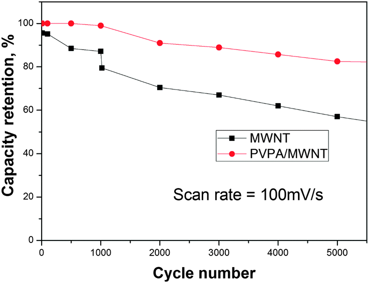 | ||
| Fig. 5 Life-cycle studies of the MWCNT and PVPA/MWCNT mixture up to 5000 cycles. | ||
In this study, PVPA has been proved to be suitable for electrical applications as a supercapcitor. To create a mixed system supercapacitor, PVPA was mixed with MWCNTs at a weight ratio of 0.85:1. After running tests, we discovered that the specific capacitance of the PVPA/MWCNT system was approximately three times that of the original system with only MWCNTs. This result is valid by studying the specific capacitance values of MWCNTs and PVPA/MWCNT at scan rates of 20 mV s−1 and 200 mV s−1. This followed our initial hypothesis of the superior performance of this mixture due to the increased carrier mobility and stability in PVPA.
This study will allow future work to explore many combinations of OLED emitters and supercapacitor materials (Fig. S4, ESI†). This is also just a starting point to the potentially large production of supercapacitors with much greater energy density.
Acknowledgements
This research was supported by a grant from the Technology Development Program for Strategic Core Materials funded by the Ministry of Trade, Industry & Energy, Republic of Korea (Project No. 10047758).Notes and references
- Q. Qu, S. Yang and X. Feng, Adv. Mater., 2011, 23, 5574 CrossRef CAS PubMed.
- C. Guan, J. Liu, C. Cheng, H. Li, X. Li and H. J. Fan, Energy Environ. Sci., 2011, 4, 4496 CAS.
- A. Najafabadi, T. Yamada, D. N. Futaba, M. Yudasaka, H. Takagi, H. Hatori, S. Lijima and K. Hata, ACS Nano, 2011, 5, 811 CrossRef PubMed.
- C. Liu, Z. Yu, D. Neff, A. Zhamu and B. Z. Jang, Nano Lett., 2010, 10, 4863 CrossRef CAS PubMed.
- E. Mitchell, A. Jimenez, R. K. Gupta, B. K. Gupta, K. Ramasamy, M. Shahabuddin and S. R. Mishrad, New J. Chem., 2015, 39, 2181 RSC.
- G. Wang, Y. Ling, F. Qian, X. Yang, X.-X. Liu and Y. Li, J. Power Sources, 2011, 196, 5209 CrossRef CAS.
- X. Li, J. Rong and B. Wei, ACS Nano, 2010, 4, 6039 CrossRef CAS PubMed.
- J. H. Kim, K.-W. Nam, S. B. Ma and K. B. Kim, Carbon, 2006, 44, 1963 CrossRef CAS.
- X. M. Feng, N. G. Chen, J. H. Zhou, Y. Li, Z. D. Huang, L. Zhang, Y. Ma, L. H. Wang and X. H. Yan, New J. Chem., 2015, 39, 2261 RSC.
- Y. Wei, H. C. Liu, Y. Jin, K. Cai, H. T Li, Y. Liu, Z. H. Kang and Q. G Zhang, New J. Chem., 2015, 37, 886 RSC.
- L. Hu, D. S. Hecht and G. Grüuner, Chem. Rev., 2010, 110, 5790 CrossRef CAS PubMed.
- D. Tasis, N. Tagmatarchis, A. Bianco and M. Prato, Chem. Rev., 2006, 106, 1105 CrossRef CAS PubMed.
- A. G. Pandolfo and A. F. Hollenkamp, J. Power Sources, 2006, 157, 11 CrossRef CAS.
- W. Lee, J. Kim, S. Chen, P. T. Hammond and Y. S. Horn, ACS Nano, 2010, 4, 3889 CrossRef PubMed.
- M. Bak, K. H. Kim, C. W. Lee and K. B. Kim, J. Mater. Chem., 2011, 21, 1984 RSC.
- D. P. Dubal and R. Holze, New J. Chem., 2013, 37, 403 RSC.
- B. R. Sankapal, H. B. Gajare, D. P. Dubal, R. B. Gore, R. R. Salunkhe and H. Ahn, Chem. Eng. J., 2014, 247, 103 CrossRef CAS.
- H. Pan, J. Y. Li and Y. P. Feng, Nanoscale Res. Lett., 2010, 5, 654 CrossRef CAS PubMed.
- C. S. Du and N. Pan, J. Power Sources, 2006, 160, 1487 CrossRef CAS.
- J. H. Kim, K. W. Nam, S. B. Ma and K. B. Kim, Carbon, 2006, 44, 1963 CrossRef CAS.
- M. M. Yang, B. Cheng, H. H. Song and X. H. Chen, Electrochim. Acta, 2010, 55, 7021 CrossRef CAS.
- C. Peng, S. Zhang, D. Jewell and G. Z. Chen, Prog. Nat. Sci., 2008, 18, 777 CrossRef CAS.
- C. Peng, S. Zhang, X. Zhou and G. Z. Chen, Energy Environ. Sci., 2010, 3, 1499 Search PubMed.
- C. Peng, D. Hu and G. Z. Chen, Chem. Commun., 2011, 47, 4105 RSC.
- S. M. Lee, H. G. Shin, B. S. Michael Park, J. H. Lee and J. W. Park, J. Nanosci. Nanotechnol., 2015, 15, 5438 CrossRef CAS PubMed.
- M. T. Lee, H. H. Chen, C. H. Liao, C. H. Tsai and C. H. Chen, Appl. Phys. Lett., 2004, 85, 3301 CrossRef CAS.
- S. L. Tao, S. D. Xu and X. H. Zhang, Chem. Phys. Lett., 2006, 429, 622 CrossRef CAS.
- M. S. Kim, B. K. Choi, T. W. Lee, D. W. Shin, S. K. Kang, J. M. Kim, S. C. Tamura and T. Y. Noh, Appl. Phys. Lett., 2007, 91, 251111 CrossRef.
- B. X. Mi, P. F. Wang, Z. Q. Gao, C. S. Lee, S. T. Lee, H. L. Hong, X. M. Chen, M. S. Wong, P. F. Xia, K. W. Cheah, C. H. Chen and W. Huang, Adv. Mater., 2008, 20, 1 CrossRef.
- S. C. Xia, R. C. Kwong, V. I. Adamovich, M. S. Weaver and J. J. Brown, Proc. 45th Annu. IEEE Int. Rel. Phys. Symp., 2007, 253 Search PubMed.
- N. C. Erickson and R. J. Holmes, Adv. Funct. Mater., 2013, 23, 5190 CrossRef CAS.
- X. F. Qiao, Y. T. Tao, Q. Wang, D. Ma and C. L. Yang, J. Appl. Phys., 2010, 108, 034508 CrossRef.
- M. D. Stoller and R. S. Ruoff, Energy Environ. Sci., 2010, 3, 1294 CAS.
- P. Sharma and T. S. Bhatti, Energy Convers. Manage., 2010, 51, 2901 CrossRef CAS.
- C. Peng, J. Jin and G. Z. Chen, Electrochim. Acta, 2007, 53, 525 CrossRef CAS.
- H. Pan, J. Y. Li and Y. P. Feng, Nanoscale Res. Lett., 2010, 5, 654 CrossRef CAS PubMed.
- C. S. Du and N. Pan, J. Power Sources, 2006, 160, 1487 CrossRef CAS.
- P. C. Chen, H. T. Chen, J. Qiu and C. W. Zhou, Nano Res., 2010, 3, 594 CrossRef CAS.
Footnote |
| † Electronic supplementary information (ESI) available. See DOI: 10.1039/c5nj01956g |
| This journal is © The Royal Society of Chemistry and the Centre National de la Recherche Scientifique 2016 |