Photocatalytic conversion of CO2 over graphene-based composites: current status and future perspective
Min-Quan
Yang
ab and
Yi-Jun
Xu
*ab
aState Key Laboratory of Photocatalysis on Energy and Environment, College of Chemistry, Fuzhou University, Fuzhou, 350002, P. R. China
bCollege of Chemistry, New Campus, Fuzhou University, Fuzhou, 350108, P. R. China. E-mail: yjxu@fzu.edu.cn
First published on 19th January 2016
Abstract
The continuous rise in the atmospheric CO2 level and the ever-increasing demand of energy have raised serious concerns about the ensuing effects on the global climate change and future energy supply. Photocatalytic conversion of CO2, which uses solar light energy to recycle CO2 into fuels and chemicals, provides a promising and straightforward strategy to simultaneously reduce the atmospheric CO2 level and fulfil the future energy demand. However, the lack of substantial development of state-of-the-art materials remains a major bottleneck of this technology. In recent years, graphene-based composite photocatalysts have gained increasing interest in CO2 conversion due to the introduction of graphene with a series of unique physicochemical properties, which has shown to play a significant role in promoting the photocatalytic solar energy conversion efficiency. In this review, we comprehensively summarize the typical literature reports on graphene-based composites for photocatalytic conversion of CO2 to produce solar fuels and chemicals. The main types of the reported graphene-based composites and the role of graphene in the composites in improving the photocatalytic performance have been elaborated. In particular, we have highlighted the possible role of graphene in tuning the product selectivity of photocatalytic reduction of CO2. Finally, perspectives on the existing problems and future research on graphene-based composites toward photocatalytic conversion of CO2 are critically discussed.
1. Introduction
The rapid development of human society since the Industrial Revolution has resulted in a dramatic rise of global demand for energy, which has increased from the average energy consumption rate of 2.8 terawatts (TW) in 1950 to 15 TW in 2010, and is projected to increase to 25–27 TW by 2050.1–3 Fossil fuels, as the most important global energy source with advantages such as being freely provided by nature, high energy content, and ease of transportation and storage, have accounted for the largest proportion, more than 80 percent, of the energy supply of the current world.1–3 The heavy reliance on fossil fuels for the production of energy leads to an explosive growth of CO2 emission into the atmosphere, which has disturbed the balance of the natural cycle of CO2 emission and uptake (fixation by terrestrial plants and microorganisms, plus underground inorganication),1 and caused a severe global climate change,1,4 resulting in a devastating impact on the living environment of humans. Additionally, the fast increase in the combustion of fossil fuels also leads to an excessive exploitation and sharp depletion of the finite global fossil fuel reserves, causing severe energy shortage crisis throughout the world since the late 1970s.5 The ever-increasing environmental issue and lack of natural energy resources have raised serious concerns about the ensuing effects on the global energy security, environmental security, economic security etc.6 Alleviating the environmental burden and seeking alternative sustainable energy supply have become the most urgent tasks of human society.In this context, semiconductor photocatalysis, a well-orchestrated mimic of natural photosynthesis (Fig. 1), reported since 1960s7 for direct conversion of solar energy to chemical energy, is likely to kill these two birds with one stone. In particular, in 1979, Inoue et al. for the first time observed the photocatalytic reduction of CO2 in aqueous suspensions of semiconductor photocatalysts such as TiO2, ZnO, CdS, GaP and SiC for the generation of methane, methanol, formaldehyde and formic acid,8 which are high energy density fuels (e.g., methane, methanol)2,6 compatible with current energy infrastructure and carbon feedstocks (e.g., formaldehyde and formic acid)1,6 available for chemical synthesis. The photocatalytic technique shows fascinating potential for recycling CO2 from the atmospheric waste product into value-added chemicals, which has been regarded as a promising method to simultaneously address the global energy and environmental issues.
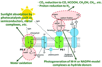 | ||
| Fig. 1 Schematic diagram of a natural photosynthetic system, with four areas of artificial photocatalysis research highlighted in red and described in green text. The artificial photocatalytic systems are designed to perform similar functions to the different components of natural photosystems, which typically focuses on one or two of these topics at a time to reduce complexity. The goal of photocatalytic reduction of CO2 is to mimic the natural photosynthetic system for the generation of renewable fuels and chemicals such as CO, formic acid, methanol and methane from CO2, H2O, and sunlight. Reprinted with permission from ref. 4. Copyright 2010 American Chemical Society.4 | ||
Over the past few decades, continuous efforts have been devoted to the photocatalytic research. A large number of new photocatalytic materials have been developed and studied for diverse photocatalytic processes,1,9–17 including the photocatalytic reduction of CO2 to produce solar fuels and chemicals.1,4,6,15–20 However, despite the significant progress made in this area, the state-of-the-art development of photocatalysis still suffers from some severe limitations such as inferior utilization of solar light, low quantum efficiency, instability of some photocatalysts (e.g., metal sulfides) and difficulty in controlling the product selectivity of some reactions (e.g., photocatalytic reduction of CO2). To overcome these challenges, different strategies including metal loading, ion doping, crystal structure, particle size and morphology control, carbonaceous nanomaterial modification, etc. have been explored.21–27
In recent years, graphene, a two-dimensional (2D) single layer of graphite with exceptional electrical, thermal, optical, and mechanical properties,28–35 has triggered a surge of research interest in both scientific and technological communities. The fabrication of graphene-based composite materials has evolved into myriad fields, including nanoelectronics, bio-sensors, energy storage and conversion, optoelectronics and supercapacitors, etc.36–38 In particular, the past several years have witnessed the cornucopia of the fabrication of graphene-based composite photocatalysts for improving the solar energy conversion efficiency.39–58 The large specific surface area, good optical transmittance, high work function and excellent electronic conductivity of graphene make it a high performance candidate for catalyst support and an electron acceptor/trapper.29,59,60 Up to now, more than 200 different kinds and over 2000 publications of graphene-based composite photocatalysts have been reported. In these literature reports, it is notable that the integration of an appropriate amount of graphene with the photoactive components obviously improves the efficiency of graphene-based composite photocatalysts toward the solar energy conversion, although the real state of graphene in the composite photocatalysts is different from that of the original defined single-layer and defect-free graphene due to the presence of defective, oxygenated functional groups and aggregation of the graphene sheets,29,60 which make it hard to take full advantage of the excellent electronic, optical and physicochemical properties of graphene. Such a situation strongly suggests that (i) the integration of graphene with a photoactive ingredient (e.g., semiconductor) to form new multicomponent composite materials provides a promising way for constructing the next-generation artificial photosynthetic systems and (ii) there is still large room to improve the performance of graphene-based composite photocatalysts by optimizing the physicochemical properties of the prepared graphene in the composites.
During the past years, some reviews have been published in the literature pertaining to the preparation and/or application of graphene-based composites.61–66 However, most of them give little attention or even neglect to cover the reaction type of photocatalytic reduction of CO2. Very recently, Low et al. have discussed the important advantages of coupling graphene with a photocatalyst for promoting the catalytic reduction of CO2 in some selected reports,67 but the comprehensive summary of the literature results of graphene-based composites for photocatalytic conversion of CO2 to produce solar fuels and chemicals is still unavailable in the literature. In particular, none of the previous reviews have highlighted the role of graphene in tuning the product selectivity for photocatalytic CO2 conversion, which is of great significance for promoting the development of photocatalytic solar fuel production. Therefore, facing the increasing research interest of this field in recent years, it is desirable and necessary to present an up-to-date insightful review of photocatalytic reduction of CO2 to produce solar fuels and chemicals over graphene-based photocatalysts, with the purpose of describing the current state and promoting further development in this area.
As such, in this critical review, we comprehensively summarize the results of graphene-based composites for photocatalytic conversion of CO2 from the following aspects. Firstly, we briefly illustrate the fundamentals of photoactivity enhancement of graphene-based composites for catalytic conversion of CO2 to solar fuels and chemicals. Secondly, after the collection of the literature reports of graphene-based composites for photocatalytic reduction of CO2, the main types of these developed graphene-based composites and the role of graphene in these composites in improving the photocatalytic performance are elaborated with selected typical examples. Thirdly, the significant role of graphene in tuning product selectivity for photocatalytic reduction of CO2 is discussed. Finally, the challenges and issues confronted by graphene-based photocatalysts for reduction of CO2 and perspectives on future research have been presented.
2. Fundamentals of photoactivity enhancement of CO2 reduction over graphene-based composites
As CO2 is a thermodynamically stable and chemically inert molecule with σ- and π-bond characteristics and a linear molecular structure O![[double bond, length as m-dash]](https://www.rsc.org/images/entities/char_e001.gif) C
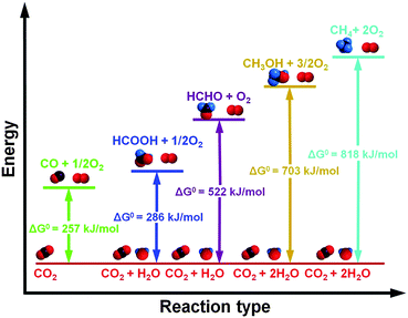
C![[double bond, length as m-dash]](https://www.rsc.org/images/entities/char_e001.gif) O, the reduction of CO2 is energetically uphill and highly endothermic. As schematically illustrated in Fig. 2, the standard Gibbs free energies (ΔG0) for the reduction of CO2 with water to carbon monoxide, methanol, methane, formaldehyde and formic acid are all highly positive,68 indicating that in order to convert CO2 into value-added chemicals and fuels, a large amount of external energy input is required, which is indispensable for overcoming the reaction barriers to break the C
O, the reduction of CO2 is energetically uphill and highly endothermic. As schematically illustrated in Fig. 2, the standard Gibbs free energies (ΔG0) for the reduction of CO2 with water to carbon monoxide, methanol, methane, formaldehyde and formic acid are all highly positive,68 indicating that in order to convert CO2 into value-added chemicals and fuels, a large amount of external energy input is required, which is indispensable for overcoming the reaction barriers to break the C![[double bond, length as m-dash]](https://www.rsc.org/images/entities/char_e001.gif) O bond and promote the formation of the C–H/C–C bond and then the final chemical products.
O bond and promote the formation of the C–H/C–C bond and then the final chemical products.
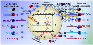
In photocatalytic reduction of CO2, solar light is adopted as the input energy source to trigger the CO2 reduction with H2O through the employment of appropriate robust and efficient photocatalysts. The primary processes of catalytic reduction of CO2 over traditional photocatalysts are shown in Fig. 3. Typically, under light irradiation, the photoactive material (taking the most widely reported semiconductor as an example) is excited to generate charge carriers (i.e. electron–hole pairs) upon the absorption of photons with energy equal to or higher than its band gap energy (Eg).1,69,70 Then, the spatially separated photogenerated electrons and holes would migrate to the catalytically active sites at the semiconductor surface (Pathways 1 and 2) and subsequently transfer to the adsorbed molecules (CO2 and H2O). The hole oxidizes the H2O to O2 and releases H+, and the electrons reduce CO2 by a sequence of reactions to produce chemicals and fuels such as CO, CH3OH and CH4 with the assistance of H+.20 However, it is notable that the photogenerated carriers would also recombine in the bulk of the semiconductor (Pathway 3, volume recombination) or on the semiconductor surface with their trapped counterparts of opposite charge (Pathway 4, surface recombination),69,70 which release the light energy in the form of heat or photons. Both of these recombination processes are detrimental to the efficiency of photocatalysis.1,70 They strongly compete with the processes of separation and transfer of photogenerated charge carriers, resulting in the low photocatalytic CO2 reduction efficiency. Therefore, promoting the separation and transfer of photogenerated charge carriers and inhibiting their recombination are essential for improving the efficiency of photocatalytic solar fuels and chemicals production.
In the case of graphene-based composite photocatalysts, the integration of graphene with the photoactive ingredient (e.g., semiconductor, organic materials etc.) has widely proven to be effective for enhancing the separation and inhibition of the recombination of charge carriers.29,59,60 Graphene with high work function is able to act as an electron acceptor/trapper to induce electron transfer from the photoactive ingredient to it,71–73 leading to the formation of an additional non-radiative delay channel for the separation and migration of photogenerated charge carriers (Pathway 5), as depicted in the right side of Fig. 3. Then, the good conductivity and high electron mobility of graphene promote the transferred electrons to diffuse fast along its unique large 2D π-conjugated structure, which efficiently improves the probability and the rate of charge carriers (i.e. electron–hole pairs) transfer in the photocatalyst.
In addition, the graphene with a large π-conjugated structure would enhance the adsorption of CO2 because the CO2 molecules also contain delocalized π-conjugation binding π34,74,75 which can form strong π–π conjugation with graphene and thus increase the local concentration of CO2 on the surface of the photocatalyst. In particular, the strong π–π conjugation between CO2 and graphene can result in the destabilization and activation of CO2 molecules.74,75 Therefore, the integration of graphene with a photoactive ingredient is not only able to enhance the separation and transfer of photogenerated charge carriers in the composite photocatalysts, but also can promote the photocatalytic reduction of CO2 to be performed on the graphene surface with low external energy, thereby significantly increasing the reaction sites and the likelihood of photogenerated electrons to interact with the adsorbed CO2 reactants. As a result, high photocatalytic activity of the graphene-based composite photocatalysts can be expected.
Moreover, the 2D structured graphene with high surface area is an excellent catalyst support. When it is utilized to integrate with the photoactive material, it is possible to promote the dispersion and inhibit the aggregation of the nanostructured photoactive component. This would result in the short diffusion length of photogenerated charge carriers and a large reactive surface for interaction with adsorbed CO2 molecules, and consequently, improved the efficiency of photocatalytic solar fuels and chemical production. Finally, in some cases, the integration of graphene with a photoactive ingredient, such as a typical TiO2 semiconductor, could extend the light absorption range of the graphene-based composite photocatalysts. The broad light absorption is also beneficial for enhancing the utilization of solar energy and improving the efficiency of photocatalytic CO2 conversion. Therefore, the integration of graphene with photoactive materials is believed to provide a wide range of opportunities to prepare diverse new graphene-based composite materials with extraordinary properties for promoting the photocatalytic conversion of CO2.
3. Summary and categories of graphene-based composite photocatalysts
Table 1 summarizes the typical reports in the literature on photocatalytic reduction of CO2 over graphene-based composite photocatalysts. An overview of the summary result shows that the graphene-based composites developed for photocatalytic reduction of CO2 mainly consisted of graphene–semiconductor photocatalysts, in which the semiconductor acts as a light harvester and graphene acts as a co-catalyst. In addition, the combination of graphene–organic composites with enzymes for photocatalytic conversion of CO2 to fuels and chemicals has also been reported, which forms the second type of graphene–organics/biomolecule photocatalysts. Moreover, some reports have shown that the graphene derivatives such as graphene oxide (GO) and nitrogen doped graphene are able to perform as semiconductors, which have proven to exhibit obvious photoactivity in reduction of CO2. Therefore, they can be regarded as another new type of graphene derivative-based photocatalysts.| Composite photocatalyst | Light source | Reaction medium | Main products | Photocatalytic performance | Ref. (year) |
|---|---|---|---|---|---|
| a MAQSP refers to multianthraquinone substituted porphyrin. b TEOA refers to triethanolamine. c IP refers to 1,1′,1′′-((20-(2-((7-amino-9,10-dioxo-9,10-dihydroanthracene-2-yl)amino)quinolin-3-yl) porphyrin-5,10,15-triyl) tris(quinoline-3,2-diyl))tris(indoline-2,3-dione). d BODIPY refers to 1-picolylamine-2-aminophenyl-3-oxy-phenyl-4,4′-difluoro-1,3,5,7-tetramethyl-2,6-diethyl-4-bora-3a,4a-diaza-s-indacene-triazine. e THPP refers to meso-tetrahydroxyphenyl porphyrin. f CoTHPP refers to cobalt tetrahydroxyphenyl porphyrin. g CoPc refers to the cobalt phthalocyanine tetrasulfonamide [Co–Pc–(SO2NH2)4] complex [(bpy)2Ru(bpm)]2RuCl2·4PF6. h TEA refers to triethylamine. i Ru refers to the ruthenium trinuclear complex. | |||||
| 1RGO–P25; 2SEG–P25 | UV light, 100 W mercury vapor lamp; visible light, 60 W daylight bulb | CO2 and H2O vapor | CH4 | UV light: 11.9 μmol m−2 h−1, the photoactivity is close to that of TiO2; 28.5 μmol m−2 h−1, 4.5-fold TiO2; visible light: 11.3 μmol m−2 h−1, 2.3-fold of TiO2; 24.0 μmol m−2 h−1, 7.2-fold of TiO2 | 76 (2011) |
| SEG–TiO2 | UV light, 100 W mercury vapor lamp; visible light, 60 W daylight bulb | CO2 and H2O vapor | CH4 | UV light: 9.3 μmol m−2 h−1, 3.5-fold of TiO2; visible light: 1.5 μmol m−2 h−1, 3.7-fold of TiO2 | 77 (2012) |
| G–TiO2 | —, 300 W xenon lamp | CO2 and H2O vapor | CH4, C2H6 | CH4, 8 μmol h−1 g−1; C2H6, 16.8 μmol h−1 g−1; the total solar fuel production rate is 1.7-fold of TiO2 | 78 (2013) |
| G–Ti0.91O2 | —, 300 W xenon lamp | CO2 and H2O vapor | CO, CH4 | CO, 8.9 μmol h−1 g−1; CH4, 1.1 μmol h−1 g−1, the total solar fuel production rate is 7.1-fold of TiO2 | 79 (2012) |
| RGO–(g-C3N4) | Visible light, 15 W daylight bulb | CO2 and H2O vapor | CH4 | 0.59 μmol h−1 g−1; 2.3-fold of g-C3N4 | 74 (2015) |
| RGO–CdS | Visible light, 300 W xenon lamp | CO2 and H2O vapor | CH4 | 2.5 μmol h−1 g−1; 12-fold of CdS | 75 (2014) |
| RGO–Cu2O | Visible light, 150 W xenon lamp | CO2 saturated Na2S solution | CO | 50 ppm h−1 g−1, 2-fold of Cu2O | 80 (2014) |
| Simulated solar light, 500 W xenon lamp | CO2 saturated NaOH solution | CH3OH | 4.2 μmol h−1 g−1, 1.5-fold of Cu2O | 81 (2014) | |
| RGO–WO3 | Visible light, 300 W xenon lamp | CO2 and H2O vapor | CH4 | 0.11 μmol h−1, the photoactivity of WO3 is negligible | 82 (2013) |
| RGO–ZnO | Simulated solar light, 500 W xenon lamp | CO2 saturated NaHCO3 solution | CH3OH | 4.6 μmol h−1 g−1; 1.7-fold of ZnO | 83 (2013) |
| G–TiO2–M, M = 1Au, 2Ag, 3Pd, 4Pt | Visible light, 15 W daylight bulb | CO2 and H2O vapor | CH4 | 10.13, 20.17, 30.2, 40.28 μmol h−1 g−1; 16, 27.9, 39.5, 413.5-fold of TiO2 | 84 (2015) |
| RGO–Ag–CdS | Visible light, 300 W xenon lamp | CO2 and H2O vapor | CO, CH4 | CO, 3.6 μmol h−1 g−1; CH4, 1.2 μmol h−1 g−1; the total solar fuel production rate is 1.4-fold of RGO–CdS | 85 (2014) |
| RGO–Fe2V4O13–CdS | Visible light, 300 W xenon lamp | CO2 and H2O vapor | CH4 | CH4, 2.3 μmol h−1 g−1; 1.5-fold of Fe2V4O13–CdS | 86 (2015) |
| RGO–Cu2O–Au/Cu | Visible light, 300 W xenon lamp | CO2 saturated H2O | CH3OH | 20.0 ppm cm−2 h−1; 7.8-fold of Cu2O | 87 (2015) |
| RGO–NiOx–Ta2O5 | UV-vis light irradiation, 400W metal halide lamp | CO2 and H2O vapor | CH3OH | 0.46 μmol h−1, 3.4-fold of NiOx–Ta2O5 | 88 (2013) |
| G–MAQSPa | Visible light, 450 W xenon lamp | CO2 bubbled Na3PO4 buffer with TEOAb | HCOOH | 55.3 μmol h−1, 2.4-fold of MAQSP | 89 (2012) |
| G–IPc | Visible light, 450 W xenon lamp | CO2 bubbled Na3PO4 buffer with TEOA | CH3OH | 11.21 μmol h−1, the photoactivity of IP is negligible | 90 (2014) |
| RGO–BODIPYd | Visible light, 450 W xenon lamp | CO2 bubbled Na3PO4 buffer with TEOA | HCOOH | 72.1 μmol h−1, 11.4-fold of BODIPY | 91 (2014) |
| (B-doped RGO)–P25 | Simulated solar light, 300 W xenon lamp | CO2 saturated Na2SO3 solution | CH4 | 1.3 μmol h−1 g−1, 5.2-fold of P25 | 92 (2014) |
| G–(N-doped TiO2) | Visible light, 15 W daylight lamp | CO2 and H2O vapor | CH4 | 0.37 μmol h−1 g−1, 10.9-fold of N-TiO2 | 93 (2014) |
| 1G–THPPe2G–CoTHPPf | Visible light, xenon lamp 100 mW cm−2 | CO2 and H2O vapor | CH4, C2H2 | 1CH4, 57 μmol h−1 m−2, C2H2, 113 μmol h−1 m−2; the total solar fuel production rate is 530-fold of THPP; 2CH4, 38 μmol h−1 m−2, C2H2, 42 μmol h−1 m−2; the total solar fuel production rate is 407-fold of CoTHPP | 94 (2014) |
| GO | Simulated solar light, 300 W halogen lamp | CO2 and H2O vapor | CH3OH | 0.17 μmol h−1 g−1, 5.7-fold of P25 | 95 (2013) |
| GO–Cu | Visible light, 300 W halogen lamp | CO2 and H2O vapor | CH3OH, CH3CHO | CH3OH, 2.9 μmol h−1, g−1 CH3CHO, 3.9 μmol h−1 g−1; the total solar fuel production rate is 62-fold of GO | 96 (2014) |
| GO–CoPcg | Visible light, 20 W white cold LED flood light | CO2 saturated TEAh/H2O solution | CH3OH | 78.8 μmol h−1 g−1, 2-fold of GO | 97 (2014) |
| GO–phen–Rui | Visible light, 20 W white cold LED flood light | CO2 saturated DMF/TEA/H2O solution | CH3OH | 82.9 μmol h−1 g−1, 1.8-fold of GO | 98 (2014) |
Consequently, in terms of different photoactive components, the as-reported graphene-based composites in the literature on photocatalytic reduction of CO2 have been classified into three main groups: graphene–semiconductor photocatalysts, graphene–organics/biomolecule photocatalysts and graphene derivatives-based photocatalysts. In the following sections, the typical examples of these different types of graphene-based composite photocatalysts and the role of graphene in these composites in improving the photocatalytic performance have been discussed separately.
3.1 Graphene–semiconductor photocatalysts
Semiconductors as the most important type of photocatalysts have been intensively investigated to couple with graphene for obtaining graphene-based composites, which have been proven to display obviously improved photocatalytic performance for reduction of CO2 than the corresponding bare semiconductors. For example, Hersam et al. have synthesized a series of graphene–TiO2 P25 (solvent exfoliated graphene SEG–P25 and solvent-reduced graphene oxide SRGO–P25) composites by a vacuum filtration method for photoreduction of CO2 to methane (CH4).76 As shown in Fig. 4A, the results show that the SEG–P25 composites with the appropriate addition of SEG exhibit a significantly higher photoactivity than bare P25 for CO2 reduction in the presence of H2O vapor under both UV and visible light irradiation. The improved photoactivity of SEG–P25 is ascribed to that SEG efficiently captures and transfers the photoelectrons generated from the excitation of TiO2, which thus inhibits the recombination of charge carriers and facilitates the reduction of CO2 to generate CH4. In contrast, it is notable that no improvement or limited photoactivity enhancement is observed for SRGO–P25 composites as compared with P25 under UV and visible light illumination, respectively. This is mainly because that SRGO obtained from solvent-reduced graphene oxide possesses high defect density and thus a large sheet resistance (Fig. 4B and C), which is unfavorable for the photoelectron separation and transfer. This work has proven that (i) graphene is able to act as an efficient co-catalyst for improving the photocatalytic activity of TiO2 for reduction of CO2 and (ii) the defect density and sheet resistance of graphene have significant influence on the photoactivity enhancement of the resulting graphene–semiconductor composite photocatalysts.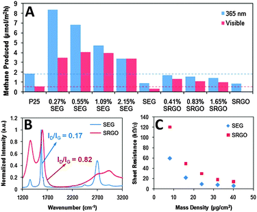 | ||
| Fig. 4 Photocatalytic activity of the SEG–P25 and SRGO–P25 composites for CO2 reduction under ultraviolet and visible light illumination (A); intensity-normalized Raman spectra of SEG and SRGO films annealed at 400 °C for 30 min in air (B); and sheet resistances of SEG and SRGO thin films formed via vacuum filtration as a function of mass density (C). Reprinted with permission from ref. 76. Copyright 2011 American Chemical Society.76 | ||
Additionally, Chai and co-workers have reported the synthesis of nitrogen doped-TiO2-001/graphene (N-TiO2-001/GR) composites by an in situ growth of well-faceted N-TiO2 with exposed (001) facets onto GR sheets for photocatalytic reduction of CO2 to CH4 in the presence of H2O vapor.93Fig. 5A displays the photoactivity test results over the as-synthesized samples, from which it can be seen that under visible light irradiation, the N-TiO2-001/GR composite exhibits the optimal CH4 yield of 3.7 μmol gcatalyst−1 after reacting for 10 h, which is approximately 11-fold higher activity than TiO2-001. In addition, the photoactivity of N-TiO2-001/GR is also better than its counterparts TiO2-001/GR, N-TiO2/GR, TiO2/GR and N-TiO2-001. The high photocatalytic performance of N-TiO2-001/GR is primarily attributed to the effective charge transportation of graphene, large exposure of catalytically active (001) facets relative to the (101) facets of N-TiO2 and high absorption of visible light of the composite, which strongly inhibit the recombination of electron–hole pairs, and simultaneously promote the activation of CO2 and utilization of solar energy over N-TiO2-001/GR,93 thereby enhancing the photocatalytic reduction of CO2, as illustrated in Fig. 5B.
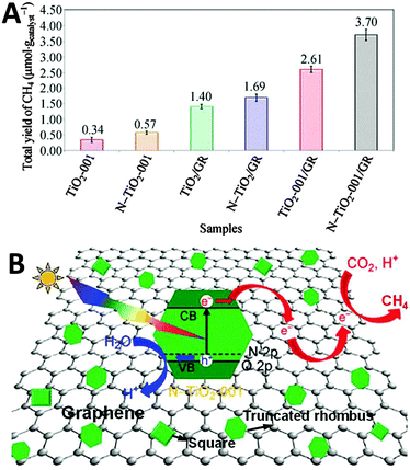 | ||
| Fig. 5 Total yield of CH4 over as-synthesized TiO2-001 and N-TiO2-001 and a series of TiO2-based/GR composites (A); schematic illustration of the charge transfer and separation of electron–hole pairs for the reduction of CO2 with H2O to CH4 using N-TiO2-001/GR composites under visible light irradiation (B). Reprinted with permission from ref. 93. Copyright 2014 Springer.93 | ||
Apart from TiO2, in a subsequent work of Chai et al., they have fabricated a series of sandwich-like graphene–(g-C3N4) (GCN) composites by a one-pot impregnation–thermal reduction strategy for the conversion of CO2 to CH4 using H2O vapor as a scavenger.74 Under visible light irradiation, the pure g-C3N4 without graphene displays low CH4 production with a total yield of 2.55 μmol gcatalyst−1 after reacting for 10 h due to a rapid recombination of electron–hole pairs, as presented in Fig. 6A and B. By integrating g-C3N4 with graphene, the as-obtained GCN samples demonstrate obviously improved photoactivity for CH4 formation. The optimal GCN-0.15 composite with the loading of 15 wt% graphene displays the maximum CH4 production yield of 5.87 μmol gcatalyst−1 among the GCN samples, which is 2.3-fold of the photoactivity of pure g-C3N4. The enhanced photocatalytic activity of GCN is accredited to the following concomitant factors. Firstly, the formation of a C–O–C bond between graphene and g-C3N4 narrows the band gap of GCN and renders the GCN composites more sensitive to the visible light region, as reflected in Fig. 6C. Secondly, the coherent interface between graphene and g-C3N4 results in a more efficient electron transfer within the 2D layered composite structure (Fig. 6D). Finally, CO2 molecules with delocalized π-conjugated binding π34 can adsorb onto the graphene surface through the π–π conjugation interaction, which is beneficial for the destabilization and activation of CO2 molecules. These factors synergistically promote the photoactivity enhancement of GNS toward visible-light-driven CO2 reduction.74
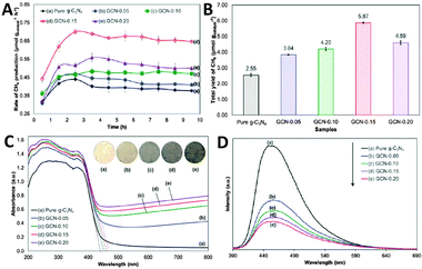 | ||
| Fig. 6 Time dependence of the photocatalytic production rate of CH4 (A) and total CH4 yield over the as-prepared photocatalysts (B); UV-Vis DRS spectra (the inset shows the color of the photocatalysts) (C) and PL spectra (D) of pure g-C3N4 and GCN composites. Reprinted with permission from ref. 74. Copyright 2015 Royal Society of Chemistry.74 | ||
Additionally, CdS as another important semiconductor has also been coupled with graphene for photocatalytic reduction of CO2. Yu and co-workers have prepared a series of reduced graphene oxide–CdS nanorods (RGO–CdS) composites via a one-step microwave-hydrothermal method in ethanolamine–water solution.75 These composite samples have shown obviously improved visible light photocatalytic activity for reduction of CO2 with H2O vapor to CH4 as compared to blank CdS. As shown in Fig. 7, the 0.5% RGO–CdS (G0.5) composite with the optimal content of RGO exhibits the highest CH4 production rate of 2.51 μmol h−1 g−1, which exceeds the rate of blank CdS nanorods by more than 10 times (0.21 μmol h−1 g−1). Moreover, the value is also higher than that of the reference 0.5% Pt–CdS nanorod composite photocatalyst (1.52 μmol h−1 g−1) under identical reaction conditions. This high photoactivity of the RGO–CdS composites has been ascribed to the deposition of CdS nanorods onto RGO sheets, which not only promotes the separation and transfer of the photogenerated charge carriers, but also enhances the adsorption and activation of CO2 molecules,75 thus resulting in the photoactivity enhancement of CO2 reduction over the RGO–CdS composites. However, in spite of the effectiveness of RGO–CdS composites for photocatalytic reduction of CO2 to CH4, the photostability of the composites is still unclear. Given that the photocatalytic reduction of CO2 over RGO–CdS composites is performed in the gaseous phase without a sacrificial reagent, it is natural to raise the question about the photocorrosion of the semiconductor CdS in the composite, which would cause a detrimental effect on the photoactivity and stability of the RGO–CdS composite photocatalysts.
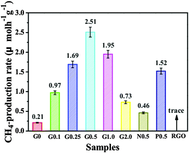 | ||
| Fig. 7 A comparison of the photocatalytic CH4 production rate of the G0, G0.1, G0.25, G0.5, G1.0, G2.0, N0.5, P0.5 and RGO samples under visible light irradiation. Reprinted with permission from ref. 75. Copyright 2015 Royal Society of Chemistry.75 | ||
Moreover, Tang and co-workers have reported the photocatalytic reduction of CO2 to CO in water over Cu2O/reduced graphene oxide (Cu2O/RGO) composites synthesized via a one-step microwave-assisted hydrothermal method.80 Before the photoactivity measurements, a thermal pretreatment of the photocatalysts in Ar or air has been performed to remove the possible trace organic contaminants in the samples. Fig. 8A and B shows the visible-light-driven catalytic reduction of CO2 over blank Cu2O and Cu2O/RGO composites in the presence of sodium sulfite as a hole scavenger. The result demonstrates that by coupling with RGO, the photoreduction activity of Cu2O has been efficiently enhanced. As to the lower photoactivity of Cu2O (air) and Cu2O/RuOx (air) than that of Cu2O (Ar), it is attributed to the partial oxidation of Cu2O to CuO upon heating, which causes a harmful effect on the photoactivity of Cu2O.80 In addition, the photoactivity test also shows that the Cu2O/0.5% RGO composite produces CO stably with an average rate of 50 ppm g−1 h−1 for 20 h, showing potential for the photocatalytic conversion of CO2 over Cu2O/RGO in a sustainable manner. The high photocatalytic activity and stability of Cu2O/RGO composites are ascribed to the electron acceptor role of RGO, which efficiently promotes charge carrier transfer and retards the electron–hole recombination (Fig. 8C). Moreover, to further clarify the origin of CO generated during the reaction, the photoreduction of 13C-labeled CO2 has been conducted, as shown in Fig. 8D. The dominant peak of 13CO (m/z = 29) clearly indicates that the evolved CO originates from the photoreduction of CO2 rather than the photodecomposition of RGO or organic contaminants that might be adsorbed onto the photocatalyst surface/reactor.
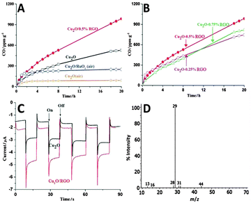 | ||
| Fig. 8 Time-dependent photocatalytic conversion of CO2 into CO over Cu2O and Cu2O/RGO composites (A); photocatalytic conversion of CO2 over Cu2O/RGO composites with different amounts of RGO (B); photocurrent response of Cu2O and Cu2O/RGO electrodes in 0.5 M Na2SO4 solution (pH = 6.8) (C); MS spectrum of the gas-phase products of 13CO2 photoreduction by the Cu2O/RGO photocatalyst (D). Reprinted with permission from ref. 80. Copyright 2014 John Wiley & Sons, Inc.80 | ||
Besides the reported binary graphene–semiconductor composites, some multinary (i.e., ternary and quaternary) graphene–semiconductor-based photocatalysts with further improved photoactivity as compared with their binary counterparts have also been fabricated for catalytic reduction of CO2 in solar fuels and chemicals.
For instance, our group has fabricated a ternary composite photocatalyst with one-dimensional (1D) silver nanowires (NWs)-doped reduced graphene oxide (RGO) integrated with a CdS nanowire network via a simple electrostatic self-assembly method followed by a hydrothermal reduction process,85 as illustrated in Fig. 9A. The integration of Ag NWs has significantly enhanced the electrical conductivity of RGO (Fig. 9B) by opening up new conduction channels for bridging the high resistance grain-boundaries of RGO with 1D Ag nanowires, which thus results in the more efficient separation and transfer of charge carriers of the Ag NWs–RGO–CdS NWs (ACG) composite than the RGO–CdS NWs (CG) sample.85 As a result, the optimal ternary Ag–CdS–2% RGO exhibits much improved photoactivity for CO2 reduction with H2O after visible light irradiation of 4 h (3.648 μmol g−1 for CO and 1.153 μmol g−1 for CH4, respectively) as compared to CdS–2% RGO (3.115 μmol g−1 for CO and 0.416 μmol g−1 for CH4, respectively), as shown in Fig. 9C.
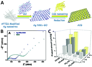 | ||
| Fig. 9 Schematic illustration of the synthesis of Ag NWs–RGO–CdS NWs (ACG) hybrid structure (A); electrochemical impedance spectroscopy (EIS) Nyquist diagrams of RGO and Ag NWs–RGO (B); the amounts of CO and CH4 formed in the photocatalytic reduction of CO2 in the presence of H2O vapor over the ACG and CG samples under visible light irradiation (C). Reprinted with permission from ref. 85. Copyright 2015 Royal Society of Chemistry.85 | ||
Additionally, Zou and co-workers have designed an all-solid-state Z-scheme system array consisting of Fe2V4O13 nanoribbons (NRs)/reduced graphene oxide (RGO)/CdS nanoparticles grown on a stainless-steel mesh (SSM) for photocatalytic conversion of CO2 with H2O vapor into CH4.86 As shown in Fig. 10A, the SEM image shows that the as-prepared Fe2V4O13 NRs with a length of 10–20 mm are perpendicularly grown on the entire SSM surface. With the GO coating and subsequent annealing treatment, the RGO-coated surface of the Fe2V4O13 NR obviously appears as a crumpled-layer structure (Fig. 10B). Then, after chemical vapor deposition of CdS, a large number of tiny CdS particles are observed on the surface of Fe2V4O13/RGO (Fig. 10C). The SEM analysis clearly demonstrates the ordered structure and the intimate interfacial contact of the three components in the resulting Fe2V4O13/RGO/CdS composite.
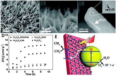 | ||
| Fig. 10 SEM images of Fe2V4O13 (A), Fe2V4O13/RGO (B) and Fe2V4O13/RGO/CdS (C); CH4 evolution activities over the as-prepared sample (D); schematic illustration of photocatalytic conversion of CO2 into CH4 over the Fe2V4O13/RGO/CdS Z-scheme system (E). (Fe2V4O13ECB: −0.55 eV, EVB: 1.28 eV; CdS ECB: −0.52 eV, EVB: 1.88 eV vs. NHE). Reprinted with permission from ref. 86. Copyright 2015 Royal Society of Chemistry.86 | ||
Fig. 10D displays the photocatalytic performance of bare Fe2V4O13, binary Fe2V4O13/RGO, Fe2V4O13/CdS and ternary Fe2V4O13/RGO/CdS toward reduction of CO2 to CH4 under visible light irradiation, which demonstrates that the ternary Fe2V4O13/RGO/CdS displays the highest photoactivity. The photoactivity enhancement has been ascribed to the formation of an efficient Z-scheme heterostructure in the ternary Fe2V4O13/RGO/CdS composite. As graphically illustrated in Fig. 10E, the photoexcited electrons from the CB of CdS may transfer to RGO and release into the VB of Fe2V4O13 to recombine with the existing holes of Fe2V4O13. The holes stored by the CdS oxidize H2O to O2, whereas the electrons stored by the Fe2V4O13 reduce CO2 to CH4.86 The presence of a RGO interlayer between Fe2V4O13 and CdS provides a high-speed charge channel in the heterostructure due to its high electron mobility, leading to more efficient spatial separation of the electrons and holes and subsequently promoting the high photocatalytic conversion efficiency of CO2.86 Notably, in the present Fe2V4O13/RGO/CdS Z-scheme system, the holes are stored by CdS to oxidize H2O to O2. However, it is well known that the S2− in CdS is easier to be oxidized by holes than that of H2O. Therefore, the photostability of this Z-schematic Fe2V4O13/RGO/CdS composite photocatalysts should be concerned.
Very recently, Hou and co-workers have developed a novel quaternary three-dimensional bimetal–graphene–semiconductor (Au–Cu/graphene/Cu2O) integrated system for solar-light-driven conversion of CO2 into methanol,87 in which the Cu2O nanowire arrays on a Cu mesh substrate are encapsulated by ultrathin graphene layers and then decorated with an optimized combination of Au–Cu nanoalloys, as displayed by the SEM and TEM images in Fig. 11A–E. The photocatalytic reduction of CO2 over the as-synthesized composites has been performed in CO2 saturated H2O. As shown in Fig. 11F, under visible light irradiation of 6 h, the methanol yield over the graphene/Cu2O array is 46.3 ppm cm−2 h−1, which is 3-fold of the photoactivity of the Cu2O array (15.4 ppm cm−2 h−1). In particular, the Au–Cu/graphene/Cu2O array exhibits the highest methanol yield of 120.0 ppm cm−2 h−1, which is 7.8 times higher than that of the Cu2O array. The recycle test of Au–Cu/graphene/Cu2O shows that the yield rate of methanol from CO2 conversion maintains 92% of its original activity after five runs, implying the high photostability of the composite. Moreover, the photoactivity of Au–Cu/graphene/Cu2O has also been proven to be much higher than that of the graphene/Cu2O array decorated with Au, Cu and Au + Cu prepared by a step-by-step deposition of metal on the support.87 The significantly improved photoactivity of Au–Cu/graphene/Cu2O is attributed to (1) the introduction of graphene as an electron conductive platform with a lower energy level than the conduction band (CB) of Cu2O leads to the photogenerated electron migration from the CB of Cu2O to the graphene layer87 and (2) the formation of a Schottky junction in a 3D Au–Cu/graphene/Cu2O system results in the further migration of electrons from graphene to Au–Cu nanoalloys.87 Furthermore, the electromagnetic field induced from the surface plasmonic resonance effect of Au–Cu also promotes the migration of electrons through the harness charge flow of Cu2O nanowire array → graphene layer → Au–Cu nanoalloys (Fig. 11G). Consequently, the electron–hole pairs are readily separated and the lifetime of the charge carriers is efficiently prolonged (Fig. 11H and I) in the quaternary 3D Au–Cu/graphene/Cu2O composites, which become readily available to drive the multi-electron CO2 reduction process.
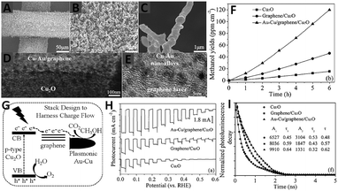 | ||
| Fig. 11 SEM (A–C), TEM (D) and HRTEM (E) images of Au–Cu/graphene/Cu2O arrays; photocatalytic production yield of methanol as a function of time over Cu2O, graphene/Cu2O, and Au–Cu/graphene/Cu2O array photocatalysts (F); diagram of the CO2 photoreduction mechanism for the Au–Cu/graphene/Cu2O array (G); photoelectrochemical performance using Na2SO4 solution (pH = 5) with potassium phosphate (H) and time-resolved photoluminescence decay spectra (excitation λ = 420 nm) for Cu2O, graphene/Cu2O, and Au–Cu/graphene/Cu2O array photocatalysts (I). Reprinted with permission from ref. 87. Copyright 2015 John Wiley & Sons, Inc.87 | ||
3.2 Graphene–organics/biomolecule photocatalysts
Organic compounds and metal organic complexes with suitable light absorption property are another important class of promising materials that are capable of participating in photochemical charge transfer and energy transfer processes.99–102 The integration of graphene with organics and metal organic complexes, such as porphyrins, phthalocyanine–iron complex and phthalocyanine–ruthenium complex, has also been employed to improve the efficiency of harvesting solar energy.103–106 In particular, some recent reports have proven that with the assistance of biological enzymes, the graphene–organics/biomolecule photocatalyst composite systems are able to catalytically convert CO2 to target products efficiently and selectively.89–91For instance, Baeg and co-workers have designed a graphene-based photocatalyst–biocatalyst coupled system, which consists of chemically converted graphene coupled multianthraquinone substituted porphyrin (CCGCMAQSP), an organometallic rhodium complex, nicotinamide adenine dinucleotide (NADH) and formate dehydrogenase, for the photocatalytic reduction of CO2 to formic acid (HCOOH) in sodium phosphate buffer solution with triethanolamine (TEOA) as a hole scavenger.89 As shown in Fig. 12A, the HCOOH yield increases linearly with the reaction time when CCGCMAQSP is used as the photocatalyst. The yield for the production of HCOOH over CCGCMAQSP within 2 h is 110.55 μmol, which is much higher than the values of the reference photocatalysts of W2Fe4Ta2O17 (14.25 μmol) and blank MAQSP (46.53 μmol). The working mechanism of the as-prepared graphene-based photocatalyst–biocatalyst coupled system for the production of formic acid from CO2 is schematically illustrated in Fig. 12B. Under visible light irradiation, MAQSP firstly absorbs photons through the transition between localized orbitals around the chromophore to generate electrons and transfer to the organometallic rhodium complex via graphene. Then, the reduced rhodium complex abstracts protons from aqueous solution and further transfers electrons and hydrides to NAD+, which converts NAD+ to NADH and finishes the photocatalytic cycle. During this process, the rhodium complex shuttles as an electron mediator between the CCGMAQSP photocatalyst and NAD+, which facilitates the regeneration of NADH. Finally, NADH is consumed by the CO2 substrate for its enzymatic (formate dehydrogenase) conversion to HCOOH. The NAD+ released from the enzyme can undergo a photocatalytic cycle in the same way, leading to the photoregeneration of NADH. These two catalytic cycles thus couple integrally to work together, ultimately yielding HCOOH from CO2.89
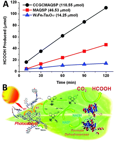 | ||
| Fig. 12 Photocatalytic activities of CCGCMAQSP, MAQSP, and W2Fe4Ta2O17 in visible-light-driven artificial photosynthesis of formic acid from CO2 (A); schematic illustration of artificial photosynthesis of formic acid from CO2 over a graphene-based photocatalyst catalyzed under visible light irradiation (B). Reprinted with permission from ref. 89. Copyright 2012 American Chemical Society.89 | ||
In a following work by Baeg et al., they have further reported the photocatalytic reduction of CO2 to methanol over another new graphene-based photocatalyst–biocatalyst integrated system, which is derived from the covalent attachment of an isatin-porphyrin (IP) chromophore to chemically converted graphene (CCG) forming a CCG–IP photocatalyst, and then coupling with enzymes.90 The production of methanol over the as-synthesized photocatalysts has been performed in CO2-saturated sodium phosphate buffer solution with the addition of a rhodium complex, mixed enzymes (formate dehydrogenase, formaldehyde dehydrogenase and alcohol dehydrogenase) and a hole scavenger of TEOA. The photoactivity test results in Fig. 13A have shown that the methanol yield of the CCG–IP photocatalyst is 11.21 μM after visible light irradiation of 1 h, which is much higher than that of the reference CCGCMAQSP photocatalyst (5.62 μM). In addition, the photoactivity test of the IP chromophore generates a trace amount of methanol which could not be quantified, while CCG fails to produce any methanol. Fig. 13B displays the transient photocurrent study of IP and CCG–IP. The CCG–IP presents significantly higher photocurrent than the IP electrode. The prompt photocurrent response of CCG–IP is in well accordance with its improved photoactivity, indicating a significant co-catalytic role of CCG for enhancing the electron transfer from IP to CCG upon visible light irradiation. Furthermore, the control experiments in the absence of CO2, a CCG–IP photocatalyst (but with enzymes) or visible light irradiation show that no methanol is formed in all these cases, which further confirm the photocatalytic nature of converting CO2 to methanol over the CCG–IP composite.
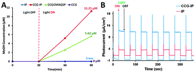 | ||
| Fig. 13 Exclusive production of methanol from CO2 under visible light by CCG–IP, CCGCMAQSP, IP, and CCG upon integration with β-NAD+, a rhodium complex, TEOA, photocatalyst, and enzymes (formate dehydrogenase, formaldehyde dehydrogenase, and alcohol dehydrogenase) in sodium phosphate buffer (A); photocurrent-time profiles of FTO/IP and FTO/CCG–IP electrodes under simulated solar light illumination (electrolyte: 0.1 M NaCl in water, bias potential: 0–0.1 V (vs. Ag/AgCl)) (B). Reprinted with permission from ref. 90. Copyright 2011 American Chemical Society.90 | ||
The above discussed studies clearly demonstrate the possibility of using photoactive graphene–organics to construct a photocatalyst–biocatalyst coupled system for catalytic reduction of CO2 to value-added chemicals and fuels. More importantly, the studies have shown the great potential for controlling the product with high selectivity through choosing appropriate biological enzymes. For example, in the presence of formate dehydrogenase alone, the photocatalytic conversion of CO2 over the CCGMAQSP composite produces formic acid,89 whereas in the case of adding mixed enzymes of formate dehydrogenase, formaldehyde dehydrogenase and alcohol dehydrogenase, methanol is detected as the exclusive product for the photocatalytic conversion of CO2 over the same CCGMAQSP photocatalyst under identical reaction conditions.90 Therefore, the design and fabrication of graphene-based photocatalyst/biomolecule composite systems would be a promising strategy for the selective photocatalytic conversion of CO2 to target products.
3.3 Graphene derivatives-based photocatalysts
In addition to the above discussed graphene–semiconductor and graphene–organics/biomolecule photocatalysts, graphene oxide (GO), the most regularly used precursor of graphene for the synthesis of graphene-based composite photocatalysts,29,60 has also recently been proven to be able to perform as a photocatalyst for solar energy conversion.107–111 In particular, GO has demonstrated to display obvious photoactivity that is comparable with traditional semiconductors such as TiO2 for catalytic reduction of CO2 to produce solar chemicals and fuels.For example, Chen et al. have reported the photocatalytic reduction of CO2 with H2O vapor to CH3OH using GO as a promising photocatalyst under simulated solar light irradiation.95 They have synthesized a series of GO samples under different oxidation conditions and found that GO-3 obtained via the Hummers oxidation with excess KMnO4 and H3PO4 exhibits the highest photocatalytic efficiency. As shown in Fig. 14A, the photocatalytic conversion rate of CO2 to CH3OH on GO-3 achieved is up to 0.172 μmol g cat−1 h−1, which is 6-fold higher than the pure TiO2 P25. The isotope tracer analysis of GO with 13CO2 demonstrates that CH3OH is produced directly from the photocatalytic reduction of CO2 instead of any photo-dissociation of the GO photocatalyst. Besides, the origin of the photoactivity has been described by the band structure of GO, as illustrated in Fig. 14B. In the GO photocatalyst, the oxygenated functional groups provide a 2D network of sp2 and sp3 bonded atoms, leading to the presence of a finite band gap depending on the isolated sp2 domains. During the photocatalytic reduction process, GO with surplus oxygenated components is photoexcited to generate electron–hole pairs, which then migrate to the GO surface to react with absorbed CO2 reactants and produce CH3OH.95
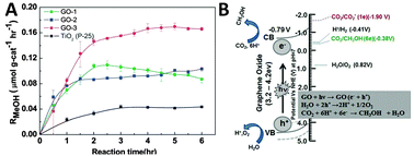 | ||
| Fig. 14 Photocatalytic methanol formation (RMeOH) on different GO samples (GO-1, GO-2, GO-3) and TiO2 using a simulated solar-light source (A) and schematic illustration of the photocatalytic CO2 reduction mechanism on GO (B). Reprinted with permission from ref. 95. Copyright 2013, Royal Society of Chemistry.95 | ||
In a subsequent work of Chen et al., they have further synthesized a series of copper nanoparticles decorated GO photocatalysts with different weight ratios of Cu via a one-step microwave method.96 The as-synthesized GO–Cu composites display significantly enhanced photocatalytic activity for reduction of CO2 to methanol and acetaldehyde in the presence of H2O vapor under visible light irradiation, as shown in Fig. 15A. The rate of formation of solar fuels (methanol and acetaldehyde) over the optimal Cu/GO–2 (10% Cu) composite (6.4 μmol g cat−1 h−1) is 60 times higher than that of pristine GO and 240 times higher than that of commercial P25 under visible light irradiation. The characterization results demonstrate that the incorporation of Cu effectively tunes the work function of GO due to the spontaneous transfer of electrons from GO to Cu nanoparticles.96 As a result, the charge separation at the GO–Cu interface and the suppression of carrier recombination are more efficient than those of GO (Fig. 15B), which thus leads to the enhanced photocatalytic CO2 reduction activity of GO–Cu composites. In addition, the variation in the production rate of different products is suggested to be determined by the band positions of these samples, as displayed in Fig. 15C. The plot shows that the conduction bands (CBs) of Cu/GO–1 (5% Cu) and Cu/GO–2 (10% Cu) are feasible for the multi-electron reduction of CO2 to methanol and acetaldehyde. In contrast, the position of the CB in Cu/GO–3 (15% Cu) is slightly lower than the CO2/CH3OH reduction potential at around −0.35 V, which leads to the removal of methanol in the product.96
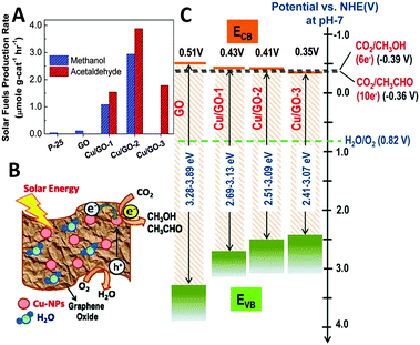 | ||
| Fig. 15 Photocatalytic solar fuel production rate for GO, and Cu/GO-1, Cu/GO–2, and Cu/GO-3 (production rate was derived following 2 h of light irradiation) (A); schematic photocatalytic reaction mechanism (B); and band-edge positions of pristine GO and Cu/GO hybrids in comparison with CO2/CH3OH and CO2/CH3CHO formation potential (C). Reprinted with permission from ref. 96. Copyright 2014 American Chemical Society.96 | ||
Additionally, Jain et al. have reported the immobilization of light responsive metal–organic complexes onto the GO support,97,98,112 which also significantly improves the photocatalytic CO2 reduction activity of GO. For example, they have immobilized ruthenium trinuclear polyazine complexes on phenanthroline modified GO through the complex formation between them.98 The as-synthesized Ru–(phen–GO) composite displays higher visible light photoactivity than GO for catalytic reduction of CO2 to CH3OH in DMF/H2O solution with the addition of triethylamine as a sacrificial agent, as shown in Fig. 16A. After 48 h of illumination, the CH3OH yield of about 3978 μmol gcat−1 is obtained, which is much higher than the yield of CH3OH over blank GO (2201 μmol gcat−1) under identical reaction conditions. The isotopic labeling experiment performed with 13CO2 confirms that the methanol formation is through CO2 reduction. In addition, the recycle test of continuous five runs demonstrates that the Ru–(phen–GO) composite is stable as well as efficient for the photocatalytic reduction of CO2 under the current experimental conditions. The enhanced photocatalytic performance of Ru–(phen–GO) composites is ascribed to the significant sensitization role of the synthesized ruthenium complex. It is able to strongly absorb visible light and be excited to inject electrons into the conduction band (CB) of GO, which subsequently reduces the adsorbed CO2 to methanol on the surface of GO. Meanwhile, the sacrificial agent of triethylamine provides electrons to the oxidized ruthenium for the continuation of the process (Fig. 16B).98
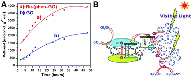 | ||
| Fig. 16 Photocatalytic conversion of CO2 to methanol over the Ru–(phen–GO) composites and GO (A) and the possible mechanism of photocatalytic CO2 reduction over Ru–(phen–GO) composites (B). Reprinted with permission from ref. 98. Copyright 2014 Royal Society of Chemistry.98 | ||
Besides the photocatalytic reduction of CO2 over GO-based composite photocatalysts, recently, Jain et al. have reported that the nitrogen-doped graphene (GrN700) obtained from annealing the dried GO-ethylenediamine material at 700 °C under an argon flow is also efficient for CO2 reduction in DMF/H2O solvent.113 In particular, they have further grafted a copper(II) complex ([Cu(bpy)2(H2O)2]Cl2·2H2O) onto the nitrogen-doped graphene (GrN700) structure, which efficiently improves the photocatalytic CO2 reduction activity by a factor of 2.05. As shown in Fig. 17A, after visible light irradiation for 24 h, the methanol production over a bare copper(II) complex (CuC), GO, GrN700, GrN700–CuC and GrN700![[thin space (1/6-em)]](https://www.rsc.org/images/entities/char_2009.gif) :
:![[thin space (1/6-em)]](https://www.rsc.org/images/entities/char_2009.gif) CuC (physical mixture) displays a total yield of 285, 420, 780, 971 and 1600 μmol g−1, respectively. The GrN700–CuC has shown the highest photoactivity among these samples. The blank experiment performed in a N2 atmosphere demonstrates that no obvious methanol generation has been detected, confirming that the CH3OH is produced directly from the photocatalytic reduction of CO2. Moreover, the recycling experiment after five runs shows that the methanol yield over GrN700–CuC is about 90% of its original photoactivity (Fig. 17B). These results indicate that the synthesized GrN700–CuC photocatalyst is quite stable and can be efficiently used for the catalytic reduction of CO2. The possible photocatalytic mechanism over GrN700–CuC is illustrated as the following. In the GrN700–CuC composite system, the N-doped graphene performed like a semiconductor, and the copper complex with good visible light absorbance works like a photosensitizer. Under visible light irradiation, the copper bipyridine complex would be photoexcited to generate electrons and then transfer to the conduction band of N-doped graphene, while the holes are scavenged by the solvent.113 Due to the high electrical conductivity and the large surface for the attachment of CO2 of N-doped graphene, the electrons in the conduction band of GrN700 efficiently reduce the CO2 molecules to CH3OH.
CuC (physical mixture) displays a total yield of 285, 420, 780, 971 and 1600 μmol g−1, respectively. The GrN700–CuC has shown the highest photoactivity among these samples. The blank experiment performed in a N2 atmosphere demonstrates that no obvious methanol generation has been detected, confirming that the CH3OH is produced directly from the photocatalytic reduction of CO2. Moreover, the recycling experiment after five runs shows that the methanol yield over GrN700–CuC is about 90% of its original photoactivity (Fig. 17B). These results indicate that the synthesized GrN700–CuC photocatalyst is quite stable and can be efficiently used for the catalytic reduction of CO2. The possible photocatalytic mechanism over GrN700–CuC is illustrated as the following. In the GrN700–CuC composite system, the N-doped graphene performed like a semiconductor, and the copper complex with good visible light absorbance works like a photosensitizer. Under visible light irradiation, the copper bipyridine complex would be photoexcited to generate electrons and then transfer to the conduction band of N-doped graphene, while the holes are scavenged by the solvent.113 Due to the high electrical conductivity and the large surface for the attachment of CO2 of N-doped graphene, the electrons in the conduction band of GrN700 efficiently reduce the CO2 molecules to CH3OH.
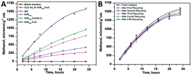 | ||
| Fig. 17 Photocatalytic conversion of CO2 into methanol using various catalytic materials under visible light irradiation (A); methanol yield from the photoreduction of CO2 under visible irradiation using fresh and recycled GrN700–CuC catalysts (B). Reprinted with permission from ref. 113. Copyright 2014 Royal Society of Chemistry.113 | ||
According to the above discussed examples reported by different research groups, it is certain that the modification of graphene such as oxidation and doping would enable the as-obtained graphene derivatives to be photocatalysts for catalytic conversion of CO2. However, the origin of the light driven photoactivity of graphene oxide and nitrogen doped graphene for catalytic reduction of CO2 is still not well understood. In addition, the photostability of the graphene derivatives-based photocatalyst, especially for the graphene oxide, is another important issue that should be carefully concerned. This is because some previous studies have proven that light irradiation of GO during the photocatalytic process would result in an obvious decrease of oxygenated functional groups and thus narrows the band-gap of GO.114
4. Tuning the product selectivity of photocatalytic conversion of CO2 over graphene-based photocatalysts
In addition to the photocatalytic activity, the selectivity toward target products is another important concern related to the photocatalytic conversion of CO2 to produce solar fuels and chemicals. Recently, some reports have proven that in addition to improving the photoactivity, the integration of graphene with the photoactive ingredient is also able to tune the product selectivity for photocatalytic reduction of CO2.For example, Zou et al. have reported the fabrication of G–Ti0.91O2 hollow spheres consisting of molecular-scale alternating Ti0.91O2 nanosheets and G nanosheets for photocatalytic reduction of CO2.79 As shown in Fig. 18, the total conversion of CO2 to renewable fuels (CO and CH4) in the presence of H2O vapor over G–Ti0.91O2 hollow spheres is five-times higher than blank Ti0.91O2 hollow spheres and nine-times higher than commercial P25. The higher photoactivity of G–Ti0.91O2 hollow spheres is attributed to the following: (i) the ultrathin nature of Ti0.91O2 nanosheets favors the rapid transportation of photoelectrons onto the surface to participate in the photoreduction; (ii) the sufficiently compact stacking of ultrathin Ti0.91O2 nanosheets with G nanosheets leads to the spatial separation of the charge carriers; and (iii) the hollow structure allows more efficient, permeable absorption and scattering of light. Notably, the photoactivity result has also shown that CH4 is the major product over the Ti0.91O2 photocatalyst, whereas CO is predominantly produced over G–Ti0.91O2 composites. This photoactivity difference indicates the significant role of graphene in determining the product for photocatalytic reduction of CO2. The possible reason has been explained as the following: the formation of CO and CH4 follows the reaction route of CO2 → CO → C˙ → CH2 → CH4 with the aid of two-electron and eight-electron transfer, respectively.79 The electrons transferred from Ti0.91O2 to G diffuse quickly over a large area of G, benefitting from the enhanced electron mobility of G. This restrains the accumulation of the electrons and decreases the local electron density, which is favorable for the two-electron reaction to form CO.
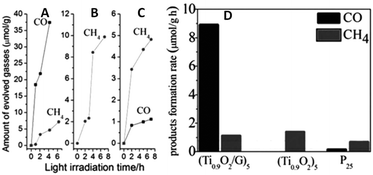 | ||
| Fig. 18 Photocatalytic CH4 (dots) and CO (squares) evolution amounts for (G–Ti0.91O2)5 hollow spheres (A), (Ti0.91O2)5 hollow spheres (B), and P25 (C); and a comparison of the average product formation rates (D). Reprinted with permission from ref. 79. Copyright 2012 John Wiley & Sons, Inc.79 | ||
In a subsequent work, Zou et al. have reported another graphene–TiO2 (G–TiO2) composite prepared by an in situ reduction–hydrolysis technique in a binary ethylenediamine (En)–H2O solvent.78 The reduction of GO to G by En and the formation of TiO2 nanoparticles loaded onto G through chemical bonds (Ti–O–C bond) are achieved simultaneously.78 In particular, owing to the reducing role of En, abundant Ti3+ is formed on the surface of TiO2 in the G–TiO2 composites. Fig. 19A displays the photocatalytic activity for the reduction of CO2 in the presence of H2O vapor over the G–TiO2 samples. The results show that 2% G–TiO2 composite displays the optimal photoactivity (8 μmol g−1 h−1 CH4 and 16.8 μmol g−1 h−1 C2H6), which is much better than blank TiO2 (10.1 μmol g−1 h−1 CH4 and 7.2 μmol g−1 h−1 C2H6) and commercial P25 (0.69 μmol g−1 h−1 CH4 and minor CO 0.16 μmol g−1 h−1, C2H6 is absent). In addition, it is notable that with the increase of the weight ratio of G in the G–TiO2 composites, the production rate of CH4 slowly decreases while the production rate of C2H6 increases to some degree (Fig. 19B and C). This photoactivity change has been ascribed to the presence of surface–Ti3+ and G in the G–TiO2 composites, which are able to couple with ˙CH3 and stabilize the ˙CH3 species via π-conjugation between the unpaired electron of the radical and aromatic regions of the G, respectively.78 As a result, the increasing accumulation of ˙CH3 over G–TiO2 significantly increases the opportunity of formation of C2H6 by the coupling of ˙CH3 and restrains the combination of ˙CH3 with H+ and e− into CH4.
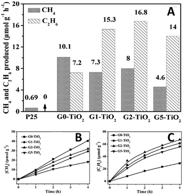 | ||
| Fig. 19 Comparison of photocatalytic activity of samples Gx–TiO2 (x = 0, 1, 2, 5; x is the weight ratio of G in the obtained samples) and P25, the molar ratio of C2H6 to CH4 increases from 0.71 (for G0–TiO2), 2.09 (G1–TiO2), and 2.10 (G2–TiO2) to 3.04 (G5–TiO2) (A); photocatalytic CH4 (B) and C2H6 (C) evolution amounts for samples Gx–TiO2 (x = 0, 1, 2, 5). Reprinted with permission from ref. 78. Copyright 2013 John Wiley & Sons, Inc.78 | ||
Moreover, Wu et al. have also reported the control of photocatalytic products for reduction of CO2 with H2O vapor over graphene-based composites.94 They synthesized two types of graphene–porphyrin composite films via a mist spray method, for which cobalt tetrahydroxyphenyl porphyrin (CoTHPP) and meso-tetrahydroxyphenyl porphyrin (THPP) are chosen as light harvesters due to their suitable light absorption property and high photostability. Fig. 20A and B displays the photoactivities of the synthesized samples, which show that THPP/G and CoTHPP/G both present higher photoactivity than their counterparts THPP and CoTHPP in terms of the yield of hydrocarbon generation. This is mainly because that the graphene sheet with high electrical conductivity can greatly increase the lifetime of photogenerated charge carriers in the composite photocatalysts and improve the adsorption of CO2 molecules, thereby enhancing the photoactivity of the THPP/G and CoTHPP/G composites. In addition, the control experiment of photocatalytic reduction of CO2 over THPP and CoTHPP without graphene has shown that only very small amounts of CH4 and trace amounts of H2 are detected, and no C2H2 is available. The result indicates that graphene plays a key role in the generation of C2H2 in the graphene–porphyrin composite system. The possible reason has been ascribed to the outstanding ability of graphene as an excellent electron transfer mediator and adsorbant for CO2, which promotes the reduction of CO2 on graphene. Simultaneously, H2O is oxidized on the porphyrin in THPP and CoTHPP, by means of which the spatial separation of photoredox processes is realized. Moreover, the reaction intermediates such as the CO2−˙ anion radical with a delocalized electronic structure can also be attached onto graphene through π–π non-covalent bonds and receive electrons uninterruptedly.94 This would improve the stability of the reaction intermediates and enhances the coupling opportunities of them, thereby promoting the formation of C2H2. As for different photoactivities between THPP/G and CoTHPP/G, the theoretical simulation result has proposed that the structural difference in the central ring of the porphyrin molecule between THPP and CoTHPP is the main reason (Fig. 20C and D). The central ring of the CoTHPP molecule is not a planar structure, which breaks the large π-structure and is adverse for the transfer of electrons to graphene for the reduction of CO2.94 Finally, the control experiments in the presence of N2 and heating of the catalysts at 50 °C without light have been carried out. No CH4 and C2H2 can be detected in these circumstances. The result confirms that the CH4 and C2H2 products are generated by the photocatalytic reduction of CO2 over the graphene–porphyrin composites.
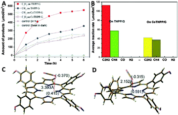 | ||
| Fig. 20 Plots of hydrocarbon generation vs. time for the porphyrin–graphene catalysts obtained using the gas-solid phase reduction method (A) and the corresponding hydrocarbon generation rate (B); the charge distribution and the distance between the positive charges and molecules: THPP+ with CO2 (C), CoTHPP+ with CO2 (D). Reprinted with permission from ref. 94. Copyright 2014 Royal Society of Chemistry.94 | ||
The above reports have obviously demonstrated the important role of graphene in tuning the product selectivity for photocatalytic reduction of CO2. With the incorporation of graphene, the synthesized graphene-based composite photocatalysts show great promise for converting CO2 into more valuable high-grade multi-carbon compounds (such as C2H2 and C2H6). However, currently, there is a lack of direct and detailed experimental evidence to support the proposed reaction mechanism for controlling the CO2 reduction product by graphene. In order to deeply exploit the potential application of graphene in promoting the photocatalytic conversion of CO2 to produce high-energy-density multi-carbon compounds, more attention and efforts should be paid to this area.
5. Summary and perspectives
In this perspective review, we have summarized the literature results reported on exploring efficient graphene-based photocatalysts for the catalytic conversion of CO2 into solar fuels and chemicals. The progress achieved by different research groups in this field demonstrates that coupling graphene with photoactive materials in a suitable manner and modification of graphene itself (e.g., oxidation and doping) hold great potential for improving the efficiency of photocatalytic conversion of CO2. However, despite the considerable developments obtained in this area, there are still some fundamental and essential issues that merit more research attention.Firstly, the photocatalytic CO2 reduction efficiencies of most of the graphene-based composites reported to date remain unsatisfactory (the rate of product formation is measured in μmol g−1 h−1). Further efforts are still required to improve the overall efficiency of the CO2 photoreduction process. In this respect, the construction of multinary graphene-based composite photocatalysts with the optimization of each component and the atomic charge carrier transfer pathway across the interface between the different components would be an effective strategy.29,60 In addition, the theoretical calculations of charge carrier dynamics within the photoactive ingredients and at their interfaces with graphene are also important.
Secondly, the photostability of the graphene-based composite photocatalysts is another important problem that should be considered. During the photocatalytic reaction process, the photoelectrons will be consumed to drive the CO2 reduction half-reaction, leaving the holes in the reaction system, which would be accumulated on the surface of the photocatalysts, and then decompose the photocatalyst component. This issue would be particularly prominent when the composite photocatalysts contain metal sulfide semiconductors, graphene oxide and organic/metal organic complexes. Given this issue, the integration of a high-performance water oxidation co-catalyst into the graphene-based composite photocatalysts to promote the fast consumption of photogenerated holes would be an effective way for enhancing the photoactivity and stability of the graphene-based composite photocatalysts.
Thirdly, the origin of photocatalytically generated products of CO2 reduction over graphene-based composites should be identified, for example, by an isotopic labeling experiment with 13CO2. This is mainly because the organic compounds in the reaction system, such as the residua obtained from the synthesis of photoactive materials with organic precursors, can be the origin of the observed products or at least can contribute in a certain percentage to the products. Moreover, considering the peculiar nature of the graphene-based composite photocatalysts with the carbon source of graphene, it is especially significant and necessary to confirm the origin of the products. However, a lot of studies commented in this review have neglected this confirmation.
Finally, the underlying photocatalytic mechanism for reduction of CO2 over graphene-based photocatalysts, and in particular, the reaction mechanism of graphene for tuning the product selectivity of photocatalytic conversion of CO2 should be clarified in detail. In this regard, the experimental and computational methods, such as in situ time-resolved spectroscopy (time-resolved fluorescence spectroscopy and femtosecond transient absorption spectroscopy), electron paramagnetic resonance spectroscopy and density functional theory calculations,20 should be integratively employed. The rational understanding of the mechanism would in turn offer guided information to design more efficient and highly selective graphene-based composites to promote the conversion of CO2 with sunlight.
Acknowledgements
The support from the Key Project of National Natural Science Foundation of China (U1463204), the National Natural Science Foundation of China (20903023 and 21173045), the Award Program for Minjiang Scholar Professorship, the Natural Science Foundation of Fujian Province for Distinguished Young Investigator Grant (2012J06003), the Independent Research Project of State Key Laboratory of Photocatalysis on Energy and Environment (No. 2014A05), the first Program of Fujian Province for Top Creative Young Talents, and the Program for Returned High-Level Overseas Chinese Scholars of Fujian province is kindly acknowledged.Notes and references
- S. N. Habisreutinger, L. Schmidt-Mende and J. K. Stolarczyk, Angew. Chem., Int. Ed., 2013, 52, 7372–7408 CrossRef CAS PubMed.
- P. D. Tran, L. H. Wong, J. Barber and J. S. C. Loo, Energy Environ. Sci., 2012, 5, 5902–5918 CAS.
- N. S. Lewis and D. G. Nocera, Proc. Natl. Acad. Sci. U. S. A., 2006, 103, 15729–15735 CrossRef CAS PubMed.
- D. C. Grills and E. Fujita, J. Phys. Chem. Lett., 2010, 1, 2709–2718 CrossRef CAS.
- J. J. Concepcion, R. L. House, J. M. Papanikolas and T. J. Meyer, Proc. Natl. Acad. Sci. U. S. A., 2012, 109, 15560–15564 CrossRef CAS PubMed.
- S. C. Roy, O. K. Varghese, M. Paulose and C. A. Grimes, ACS Nano, 2010, 4, 1259–1278 CrossRef CAS PubMed.
- H. Tong, S. Ouyang, Y. Bi, N. Umezawa, M. Oshikiri and J. Ye, Adv. Mater., 2012, 24, 229–251 CrossRef CAS PubMed.
- T. Inoue, A. Fujishima, S. Konishi and K. Honda, Nature, 1979, 277, 637–638 CrossRef CAS.
- X. Chen, C. Li, M. Gratzel, R. Kostecki and S. S. Mao, Chem. Soc. Rev., 2012, 41, 7909–7937 RSC.
- N. Zhang, R. Ciriminna, M. Pagliaro and Y.-J. Xu, Chem. Soc. Rev., 2014, 43, 5276–5287 RSC.
- C. Chen, W. Ma and J. Zhao, Chem. Soc. Rev., 2010, 39, 4206–4219 RSC.
- J. C. Colmenares and R. Luque, Chem. Soc. Rev., 2014, 43, 765–778 RSC.
- M. R. Hoffmann, S. T. Martin, W. Choi and D. W. Bahnemann, Chem. Rev., 1995, 95, 69–96 CrossRef CAS.
- X. Lang, X. Chen and J. Zhao, Chem. Soc. Rev., 2014, 43, 473–486 RSC.
- S. Navalón, A. Dhakshinamoorthy, M. Álvaro and H. Garcia, ChemSusChem, 2013, 6, 562–577 CrossRef PubMed.
- A. Corma and H. Garcia, J. Catal., 2013, 308, 168–175 CrossRef CAS.
- W. Fan, Q. Zhang and Y. Wang, Phys. Chem. Chem. Phys., 2013, 15, 2632–2649 RSC.
- K. Mori, H. Yamashita and M. Anpo, RSC Adv., 2012, 2, 3165–3172 RSC.
- M. Anpo, J. CO2 Util., 2013, 1, 8–17 CrossRef CAS.
- L. Yuan and Y.-J. Xu, Appl. Surf. Sci., 2015, 342, 154–167 CrossRef CAS.
- L. Jing, W. Zhou, G. Tian and H. Fu, Chem. Soc. Rev., 2013, 42, 9509–9549 RSC.
- C. Han, M.-Q. Yang, B. Weng and Y.-J. Xu, Phys. Chem. Chem. Phys., 2014, 16, 16891–16903 RSC.
- R. Asahi, T. Morikawa, H. Irie and T. Ohwaki, Chem. Rev., 2014, 114, 9824–9852 CrossRef CAS PubMed.
- N. Zhang, S. Liu and Y.-J. Xu, Nanoscale, 2012, 4, 2227–2238 RSC.
- G. Liu, H. G. Yang, J. Pan, Y. Q. Yang, G. Q. Lu and H.-M. Cheng, Chem. Rev., 2014, 114, 9559–9612 CrossRef CAS PubMed.
- R. Leary and A. Westwood, Carbon, 2011, 49, 741–772 CrossRef CAS.
- Y. H. Ng, S. Ikeda, M. Matsumura and R. Amal, Energy Environ. Sci., 2012, 5, 9307–9318 CAS.
- K. S. Novoselov, A. K. Geim, S. V. Morozov, D. Jiang, Y. Zhang, S. V. Dubonos, I. V. Grigorieva and A. A. Firsov, Science, 2004, 306, 666–669 CrossRef CAS PubMed.
- N. Zhang, M.-Q. Yang, S. Liu, Y. Sun and Y.-J. Xu, Chem. Rev., 2015, 115, 10307–10377 CrossRef CAS PubMed.
- M. J. Allen, V. C. Tung and R. B. Kaner, Chem. Rev., 2010, 110, 132–145 CrossRef CAS PubMed.
- S. Stankovich, D. A. Dikin, G. H. B. Dommett, K. M. Kohlhaas, E. J. Zimney, E. A. Stach, R. D. Piner, S. T. Nguyen and R. S. Ruoff, Nature, 2006, 442, 282–286 CrossRef CAS PubMed.
- K. S. Novoselov, V. I. Falko, L. Colombo, P. R. Gellert, M. G. Schwab and K. Kim, Nature, 2012, 490, 192–200 CrossRef CAS PubMed.
- A. K. Geim, Science, 2009, 324, 1530–1534 CrossRef CAS PubMed.
- A. K. Geim and K. S. Novoselov, Nat. Mater., 2007, 6, 183–191 CrossRef CAS PubMed.
- Y. Zhang, Z.-R. Tang, X. Fu and Y.-J. Xu, ACS Nano, 2010, 4, 7303–7314 CrossRef CAS PubMed.
- M.-Q. Yang, X. Pan, N. Zhang and Y.-J. Xu, CrystEngComm, 2013, 15, 6819–6828 RSC.
- X. Xie, K. Kretschmer and G. Wang, Nanoscale, 2015, 7, 13278–13292 RSC.
- Y. Zhang, Z.-R. Tang, X. Fu and Y.-J. Xu, ACS Nano, 2011, 5, 7426–7435 CrossRef CAS PubMed.
- N. Zhang, Y. Zhang, X. Pan, M.-Q. Yang and Y.-J. Xu, J. Phys. Chem. C, 2012, 116, 18023–18031 CAS.
- J. Zhang, F.-X. Xiao, G. Xiao and B. Liu, Nanoscale, 2014, 6, 11293–11302 RSC.
- A. Ye, W. Fan, Q. Zhang, W. Deng and Y. Wang, Catal. Sci. Technol., 2012, 2, 969–978 CAS.
- M.-Q. Yang, B. Weng and Y.-J. Xu, Langmuir, 2013, 29, 10549–10558 CrossRef CAS PubMed.
- B. Liu, L. Tian and Y. Wang, ACS Appl. Mater. Interfaces, 2013, 5, 8414–8422 CAS.
- H. Zhang, X. Lv, Y. Li, Y. Wang and J. Li, ACS Nano, 2010, 4, 380–386 CrossRef CAS PubMed.
- W. Fan, Q. Lai, Q. Zhang and Y. Wang, J. Phys. Chem. C, 2011, 115, 10694–10701 CAS.
- L. Yuan, M.-Q. Yang and Y.-J. Xu, Nanoscale, 2014, 6, 6335–6345 RSC.
- M.-Q. Yang, Y. Zhang, N. Zhang, Z.-R. Tang and Y.-J. Xu, Sci. Rep., 2013, 3, 3314 Search PubMed.
- M.-Q. Yang and Y.-J. Xu, J. Phys. Chem. C, 2013, 117, 21724–21734 CAS.
- N. Zhang, M.-Q. Yang, Z.-R. Tang and Y.-J. Xu, ACS Nano, 2014, 8, 623–633 CrossRef CAS PubMed.
- C. Han, Z. Chen, N. Zhang, J. C. Colmenares and Y.-J. Xu, Adv. Funct. Mater., 2015, 25, 221–229 CrossRef CAS.
- M. Gao, C. K. N. Peh, W. L. Ong and G. W. Ho, RSC Adv., 2013, 3, 13169–13177 RSC.
- X. Cao, G. Tian, Y. Chen, J. Zhou, W. Zhou, C. Tian and H. Fu, J. Mater. Chem. A, 2014, 2, 4366–4374 CAS.
- B. Qiu, M. Xing and J. Zhang, J. Am. Chem. Soc., 2014, 136, 5852–5855 CrossRef CAS PubMed.
- A. Iwase, Y. H. Ng, Y. Ishiguro, A. Kudo and R. Amal, J. Am. Chem. Soc., 2011, 133, 11054–11057 CrossRef CAS PubMed.
- X. Pan, M.-Q. Yang, Z.-R. Tang and Y.-J. Xu, J. Phys. Chem. C, 2014, 118, 27325–27335 CAS.
- Y. Zhang, N. Zhang, Z.-R. Tang and Y.-J. Xu, ACS Nano, 2012, 6, 9777–9789 CrossRef CAS PubMed.
- N. Zhang, Y. Zhang, M.-Q. Yang, Z.-R. Tang and Y.-J. Xu, J. Catal., 2013, 299, 210–221 CrossRef CAS.
- F.-X. Xiao, J. Miao and B. Liu, J. Am. Chem. Soc., 2014, 136, 1559–1569 CrossRef CAS PubMed.
- M.-Q. Yang and Y.-J. Xu, Phys. Chem. Chem. Phys., 2013, 15, 19102–19118 RSC.
- M.-Q. Yang, N. Zhang, M. Pagliaro and Y.-J. Xu, Chem. Soc. Rev., 2014, 43, 8240–8254 RSC.
- N. Zhang and Y.-J. Xu, CrystEngComm, 2016, 18, 24–37 RSC.
- G. Xie, K. Zhang, B. Guo, Q. Liu, L. Fang and J. R. Gong, Adv. Mater., 2013, 25, 3820–3839 CrossRef CAS PubMed.
- X. An and J. C. Yu, RSC Adv., 2011, 1, 1426–1434 RSC.
- P. V. Kamat, J. Phys. Chem. Lett., 2011, 2, 242–251 CrossRef CAS.
- N. Zhang, Y. Zhang and Y.-J. Xu, Nanoscale, 2012, 4, 5792–5813 RSC.
- Q. Xiang, B. Cheng and J. Yu, Angew. Chem., Int. Ed., 2015, 54, 11350–11366 CrossRef CAS PubMed.
- J. Low, J. Yu and W. Ho, J. Phys. Chem. Lett., 2015, 6, 4244–4251 CrossRef CAS PubMed.
- J. R. Bolton, Science, 1978, 202, 705–711 CAS.
- F.-X. Xiao, J. Miao, H. B. Tao, S.-F. Hung, H.-Y. Wang, H. B. Yang, J. Chen, R. Chen and B. Liu, Small, 2015, 11, 2115–2131 CrossRef CAS PubMed.
- S. Liu, Z.-R. Tang, Y. Sun, J. C. Colmenares and Y.-J. Xu, Chem. Soc. Rev., 2015, 44, 5053–5075 RSC.
- L. Yuan, M.-Q. Yang and Y.-J. Xu, J. Mater. Chem. A, 2014, 2, 14401–14412 CAS.
- L.-L. Tan, S.-P. Chai and A. R. Mohamed, ChemSusChem, 2012, 5, 1868–1882 CrossRef CAS PubMed.
- B. Weng, M.-Q. Yang, N. Zhang and Y.-J. Xu, J. Mater. Chem. A, 2014, 2, 9380–9389 CAS.
- W.-J. Ong, L.-L. Tan, S.-P. Chai and S.-T. Yong, Chem. Commun., 2015, 51, 858–861 RSC.
- J. Yu, J. Jin, B. Cheng and M. Jaroniec, J. Mater. Chem. A, 2014, 2, 3407–3416 CAS.
- Y. T. Liang, B. K. Vijayan, K. A. Gray and M. C. Hersam, Nano Lett., 2011, 11, 2865–2870 CrossRef CAS PubMed.
- Y. T. Liang, B. K. Vijayan, O. Lyandres, K. A. Gray and M. C. Hersam, J. Phys. Chem. Lett., 2012, 3, 1760–1765 CrossRef CAS PubMed.
- W. Tu, Y. Zhou, Q. Liu, S. Yan, S. Bao, X. Wang, M. Xiao and Z. Zou, Adv. Funct. Mater., 2013, 23, 1743–1749 CrossRef CAS.
- W. Tu, Y. Zhou, Q. Liu, Z. Tian, J. Gao, X. Chen, H. Zhang, J. Liu and Z. Zou, Adv. Funct. Mater., 2012, 22, 1215–1221 CrossRef CAS.
- X. An, K. Li and J. Tang, ChemSusChem, 2014, 7, 1086–1093 CrossRef CAS PubMed.
- A. Wang, X. Li, Y. Zhao, W. Wu, J. Chen and H. Meng, Powder Technol., 2014, 261, 42–48 CrossRef CAS.
- P.-Q. Wang, Y. Bai, P.-Y. Luo and J.-Y. Liu, Catal. Commun., 2013, 38, 82–85 CrossRef CAS.
- X. Li, Q. Wang, Y. Zhao, W. Wu, J. Chen and H. Meng, J. Colloid Interface Sci., 2013, 411, 69–75 CrossRef CAS PubMed.
- L.-L. Tan, W.-J. Ong, S.-P. Chai and A. R. Mohamed, Appl. Catal., B, 2015, 166–167, 251–259 CrossRef CAS.
- S. Liu, B. Weng, Z.-R. Tang and Y.-J. Xu, Nanoscale, 2015, 7, 861–866 RSC.
- P. Li, Y. Zhou, H. Li, Q. Xu, X. Meng, X. Wang, M. Xiao and Z. Zou, Chem. Commun., 2015, 51, 800–803 RSC.
- J. Hou, H. Cheng, O. Takeda and H. Zhu, Angew. Chem., 2015, 127, 8600–8604 CrossRef.
- X.-J. Lv, W.-F. Fu, C.-Y. Hu, Y. Chen and W.-B. Zhou, RSC Adv., 2013, 3, 1753–1757 RSC.
- R. K. Yadav, J.-O. Baeg, G. H. Oh, N.-J. Park, K.-j. Kong, J. Kim, D. W. Hwang and S. K. Biswas, J. Am. Chem. Soc., 2012, 134, 11455–11461 CrossRef CAS PubMed.
- R. K. Yadav, G. H. Oh, N.-J. Park, A. Kumar, K.-j. Kong and J.-O. Baeg, J. Am. Chem. Soc., 2014, 136, 16728–16731 CrossRef CAS PubMed.
- R. K. Yadav, J.-O. Baeg, A. Kumar, K.-j. Kong, G. H. Oh and N.-J. Park, J. Mater. Chem. A, 2014, 2, 5068–5076 CAS.
- M. Xing, F. Shen, B. Qiu and J. Zhang, Sci. Rep., 2014, 4, 6341 CrossRef CAS PubMed.
- W.-J. Ong, L.-L. Tan, S.-P. Chai, S.-T. Yong and A. Mohamed, Nano Res., 2014, 7, 1528–1547 CrossRef CAS.
- T. Wu, L. Zou, D. Han, F. Li, Q. Zhang and L. Niu, Green Chem., 2014, 16, 2142–2146 RSC.
- H.-C. Hsu, I. Shown, H.-Y. Wei, Y.-C. Chang, H.-Y. Du, Y.-G. Lin, C.-A. Tseng, C.-H. Wang, L.-C. Chen, Y.-C. Lin and K.-H. Chen, Nanoscale, 2013, 5, 262–268 RSC.
- I. Shown, H.-C. Hsu, Y.-C. Chang, C.-H. Lin, P. K. Roy, A. Ganguly, C.-H. Wang, J.-K. Chang, C.-I. Wu, L.-C. Chen and K.-H. Chen, Nano Lett., 2014, 14, 6097–6103 CrossRef CAS PubMed.
- P. Kumar, A. Kumar, B. Sreedhar, B. Sain, S. S. Ray and S. L. Jain, Chem. – Eur. J., 2014, 20, 6154–6161 CrossRef CAS PubMed.
- P. Kumar, B. Sain and S. L. Jain, J. Mater. Chem. A, 2014, 2, 11246–11253 CAS.
- M. L. Marin, L. Santos-Juanes, A. Arques, A. M. Amat and M. A. Miranda, Chem. Rev., 2012, 112, 1710–1750 CrossRef CAS PubMed.
- C. G. Silva, A. Corma and H. Garcia, J. Mater. Chem., 2010, 20, 3141–3156 RSC.
- M. Alvaro, E. Carbonell, B. Ferrer, F. X. Llabrés i Xamena and H. Garcia, Chem. – Eur. J., 2007, 13, 5106–5112 CrossRef CAS PubMed.
- M. A. Nasalevich, M. van der Veen, F. Kapteijn and J. Gascon, CrystEngComm, 2014, 16, 4919–4926 RSC.
- P. Wang, N. M. Dimitrijevic, A. Y. Chang, R. D. Schaller, Y. Liu, T. Rajh and E. A. Rozhkova, ACS Nano, 2014, 8, 7995–8002 CrossRef CAS PubMed.
- M. Zhu, Z. Li, B. Xiao, Y. Lu, Y. Du, P. Yang and X. Wang, ACS Appl. Mater. Interfaces, 2013, 5, 1732–1740 CAS.
- M. Zhu, Y. Dong, B. Xiao, Y. Du, P. Yang and X. Wang, J. Mater. Chem., 2012, 22, 23773–23779 RSC.
- L. Shen, L. Huang, S. Liang, R. Liang, N. Qin and L. Wu, RSC Adv., 2014, 4, 2546–2549 RSC.
- T.-F. Yeh, F.-F. Chan, C.-T. Hsieh and H. Teng, J. Phys. Chem. C, 2011, 115, 22587–22597 CAS.
- K. Krishnamoorthy, R. Mohan and S.-J. Kim, Appl. Phys. Lett., 2011, 98, 244101 CrossRef.
- T.-F. Yeh, J.-M. Syu, C. Cheng, T.-H. Chang and H. Teng, Adv. Funct. Mater., 2010, 20, 2255–2262 CrossRef CAS.
- T.-F. Yeh, C.-Y. Teng, S.-J. Chen and H. Teng, Adv. Mater., 2014, 26, 3297–3303 CrossRef CAS PubMed.
- T.-F. Yeh, J. Cihlář, C.-Y. Chang, C. Cheng and H. Teng, Mater. Today, 2013, 16, 78–84 CrossRef CAS.
- P. Kumar, A. Bansiwal, N. Labhsetwar and S. L. Jain, Green Chem., 2015, 17, 1605–1609 RSC.
- P. Kumar, H. P. Mungse, O. P. Khatri and S. L. Jain, RSC Adv., 2015, 5, 54929–54935 RSC.
- Y. Matsumoto, M. Koinuma, S. Ida, S. Hayami, T. Taniguchi, K. Hatakeyama, H. Tateishi, Y. Watanabe and S. Amano, J. Phys. Chem. C, 2011, 115, 19280–19286 CAS.
| This journal is © The Royal Society of Chemistry 2016 |


