Molecular engineering of fluorescein dyes as complementary absorbers in dye co-sensitized solar cells†
Giulio
Pepe
a,
Jacqueline M.
Cole
*abcd,
Paul G.
Waddell‡
ae and
Joseph R. D.
Griffiths
a
aCavendish Laboratory, University of Cambridge, J. J. Thomson Avenue, Cambridge, CB3 0HE, UK. E-mail: jmc61@cam.ac.uk
bISIS Neutron and Muon Source, STFC Rutherford Appleton Laboratory, Harwell Science and Innovation Campus, Didcot, Oxfordshire OX11 0QX, UK
cArgonne National Laboratory, 9700 S. Cass Avenue, Argonne, IL 60439, USA
dDepartment of Chemical Engineering and Biotechnology, University of Cambridge, Charles Babbage Road, Cambridge, CB3 0FS, UK
eAustralian Nuclear Science and Technology Organisation, Lucas Heights, NSW 2234, Australia
First published on 22nd September 2016
Abstract
Fluorescein dye derivatives exhibit extended optical absorption up to 500 nm, rendering these compounds suitable as co-absorbers in dye-sensitized solar cells (DSCs). A molecular engineering approach is presented, which embraces this intrinsic optical attribute of fluoresceins, while modifying the dye chemistry to enhance their light harvesting efficiency, in order to effectively tailor them for DSC applications. This approach first realizes relationships between the molecular structure and the optoelectronic properties for a series of five a priori known (parent) fluorescein dyes: 5-carboxyfluorescein (1), a mixture of m-carboxyfluorescein where m = 5 or 6 (2), 5-carboxyfluorescein diacetate (3), 6-carboxyfluorescein diacetate (4), a mixture of n-carboxy-2′,7′-dichlorofluorescein diacetate where n = 5 or 6 (5). The first step in this approach combines, where available, experimental and computational methods so that electronic structure calculations can also be validated for representative fluorescein dyes. Such calculations can then be used reliably to predict the structure and properties of fluorescein dyes for cases where experimental data are lacking. Structure–function relationships established from this initial step inform the selection of parent dye 1, which is taken forward to the second step in molecular engineering: in silico chemical derivation to re-functionalize 1 for DSC applications. For this purpose, computational calculations are used to extend the charge conjugation in 1 between its donor and acceptor moieties. These structural modifications result in a bathochromic shift of the lowest excitation by ∼1.3–1.9 eV (100–170 nm), making the dye optically absorb in the visible region. Further calculations on dye molecules adsorbed onto the surface of a TiO2 cluster are used to investigate the dye sensitization behavior via dye adsorption energies and anchoring modes. The results of this theoretical investigation lead to two molecularly engineered fluoresceins being proposed to act as co-sensitizers together with a rhodamine dye. This combination of three dyes ensures chemical compatibility, panchromatic absorption, and restores optical absorption dipping otherwise observed in a DSC device at ∼350–400 nm owing to the I−/I3− electrolyte. Overall, the results of this study demonstrate that molecular engineering can be used to identify suitable chemical modifications for organic dyes with improved light harvesting properties for photovoltaic applications.
Design, System, ApplicationThe transparent and low-cost nature of dye-sensitized solar cells (DSCs) affords them niche prospects for solar-powered windows, which could provide energy-sustainable buildings for future cities. However, the technology suffers from a material bottleneck: we need more efficient light-harvesting dyes which also deliver electronic charge to its semiconducting TiO2 working electrode counterpart to initiate the photovoltaic current. Since these dyes operate at the molecular scale, they would highly benefit from rational design whereby their optical and charge transfer functionality was systematically tailored. To this end, a molecular engineering strategy was employed to design better fluorescein dyes for DSC applications. A set of ‘parent’ fluorescein dyes bearing unsuitable optical absorption and charge transfer properties for DSC functionality was structurally modified to engineer DSC-desirable dye features: panchromatic UV-vis light absorption; good dye-to-TiO2 binding ability, whereby the dye ‘anchors’ to the TiO2 surface and injects an electron into its conduction band to initiate electrical current; sufficiently ‘push-pull’ intramolecular charge transfer with charge directing towards this ‘anchor’; quantum energy levels that are interoperable with other device components. In silico computation is used to design these features into the parent fluorescein dyes, generating new fluorescein derivatives, several of which prospect good potential as co-sensitizers for DSCs. |
1 Introduction
The development of renewable energy technologies is of the utmost importance, especially considering the accelerating depletion of fossil fuels,1 the harmful environmental effects associated with their combustion,2 and the steadily increasing global demand for energy. Dye-sensitized solar cells (DSCs) represent a promising photovoltaic solution to this problem, as they are cheaper to produce than their silicon counterparts, exhibit excellent indoor performance,3 and potentially offer applications in building-integrated photovoltaics (BIPV) as solar-powered ‘smart windows’.4–6 However, their power conversion efficiencies (PCEs) still remain lower than those of other types of photovoltaic devices, and DSCs have therefore been limited to niche, rather than generic applications.7Nevertheless, recent efforts in the co-sensitization of dyes for DSC applications have significantly increased PCEs, which place DSCs in a competitive position in the general photovoltaic market. For example, the PCE of a zinc-based porphyrin dye (∼9.5%) was augmented by ∼3% upon co-sensitization to produce the world-record DSC performance in 2011.8 Last year, this benchmark was surpassed by using, for the first time, a combination of metal-free organic dyes, where co-sensitization yielded 14.3% PCE under one sun illumination.9
Despite these successes, rational systematic molecular design strategies based on engineering co-sensitized DSCs (hereafter called co-DSCs) still remain elusive. Applying such design strategies to DSC dyes would be particularly helpful since the dye is one of the most important DSC device components, whose function can be controlled at the molecular level. The dye fulfills two central tasks in a DSC: light harvesting and driving the initiation of the electrical current via the dye⋯TiO2 electron injection process (TiO2 being the most common choice of semi-conducting mesoporous layer3).
Accordingly, the optical absorption profile of a dye, which is determined by the molecular structure, strongly influences its DSC performance. The optical absorption profile should be as broad as possible so that the dye can harness the maximum range of the solar spectrum. Ru-based dyes historically feature as the most commonly used DSC sensitizers, owing to the good breadth of their UV/vis absorption spectra.10 However, given their high cost, toxicity, and the relative scarcity of the transition metal ruthenium, it is hardly surprising that metal-free organic dyes have recently received more attention,11 mostly on account of their high molar extinction coefficients (ε) and their low toxicity. Moreover, they are easily available and cost effective.3 Relative to metal–organic dyes, though, a major drawback of organic dyes is their typically narrow optical absorption spectra, which limit the maximum short-circuit current density (JSC) attainable.12 However, this problem can be tackled by co-sensitization. Indeed, one of the key benefits of co-DSCs is that the co-sensitization of multiple dyes allows absorbing light at complementary wavelengths, so that their combined use results in a device that exhibits a broad optical absorption spectrum.13
To this end, we have recently reported four case studies, each prospecting co-DSC applications for a chemical family of dyes: 4-(1,3-pentadienyl)-N,N-dimethylanilines,14 oxazines,15 cyanines,16 and rhodamines.17 These studies used a combined experimental and computational approach to successively elucidate and exploit relationships between dye structure and optical function in a chemical family of molecular chromophores that were a priori known as dyes for other applications. The structure–function relationships, so formed for the dyes in three of those studies,14–16 were subsequently used as reference dyes in a molecular engineering workflow that was designed to generate new, hypothetical chemical derivatives, via computational calculations. Suitable DSC dyes exhibited attributes such as appropriate dye⋯TiO2 anchoring groups and optical absorption spectra that complement those of other dyes within this hypothetical series, to the extent that the co-sensitization of certain pairs of these computationally generated dyes were predicted to afford an overall panchromatic optical response in a co-DSC device.
The study presented herein, employs a similar combined experimental and computational approach to uncover relationships between molecular structure and optical function for fluorescein dyes. The rationale for combining experimental and computational methods for studying this set of dyes is twofold: (i) molecular properties can be analyzed from an experimental and theoretical perspective, confirming the results of theoretical calculations via reliable experiments, and (ii) computational calculations may provide information that might potentially not be attainable experimentally. Various obstacles commonly faced during experimental procedures, such as obtaining a required level of purity for a compound, crystallization difficulties, solubility issues, or limited sample quantities, can be circumvented by employing a theoretical approach. In this study, we managed to collect only limited experimental information on fluoresceins, and in two instances had only dye mixtures available, which motivated us to employ computational calculations and molecular engineering, i.e. theoretical structural modifications of these dyes, to predict sensitizers with improved DSC properties.
Looking ahead, a more general point regarding the availability of experimental data is worth adding. While the aforementioned experimental limitations have historically been confined to issues in the chemical production or characterization of a given material, a new type of missing experimental data is emerging. As the ‘big data’ research field starts to unfold, large sets of data, sourced from a multitude of different experimental studies, will become available for data-mining studies. These assembled material databases will contain manifold quantities of missing experimental data, owing to their fragmented and diverse origins. Accordingly, molecular engineering workflows based on in silico computational methods that have been validated by all relevant experimental data that is available, will become increasingly important to fill the experimental data gaps in chemical databases with reliable computationally-generated chemical data; these computational data will also complement experimental information where it exists. Such molecular engineering workflows that function on a small scale are needed in preparation for dealing with this nascent ‘big data’ issue. That way, workflows can eventually be scaled up to overcome missing data from ‘big data’ initiatives. Placing these considerations in the context of this case study, the molecular engineering of fluorescein dyes for co-DSC applications represents one of the many examples of this type of development that are needed to maximize the potential of ‘big data’ analysis for materials chemistry.
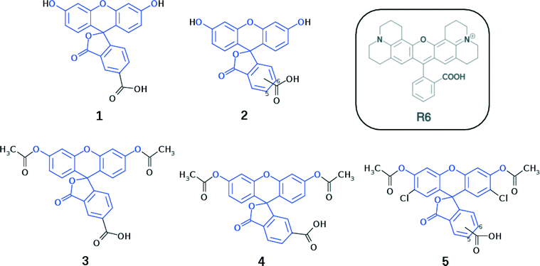
Fluorescein dyes are commonly used in biological research, as their high fluorescence quantum yields render these compounds attractive fluorescent probes for labeling macromolecules.18 The high molecular extinction coefficient of fluoresceins and their high photostability are additional attractive features for DSC sensitizers. Structurally, fluoresceins consist of a xanthene ring with terminal oxygen atoms that is connected to a benzoxolane moiety through a quaternary carbon atom (Fig. 1).
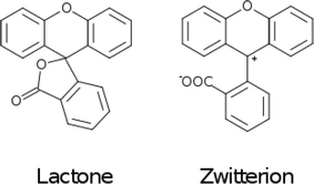
The fluoresceins used in this study may adopt two isomeric forms: lactone and zwitterion (Fig. 2). Our earlier studies on a series of the structurally-related rhodamine dyes revealed substantially different optical absorption profiles for each isomer.17 The results of the computational aspects of that study on rhodamines suggested increased levels of π-conjugation between the two principal moieties (in this case: xanthene and benzoxolane moieties) of zwitterionic dyes, resulting in a bathochromic shift of the absorption. This structure–property relationship can be used to facilitate panchromatic light harvesting in co-DSCs.
We herein examine experimentally five fluoresceins that contain a carboxylic anchoring group at different positions and acetyl groups on the terminal nitrogen atoms, in order to determine their structure, charge conjugation and spectral properties in the lactone and zwitterionic isomers: 5-carboxyfluorescein (1), a mixture of m-carboxyfluorescein where m = 5 (para) or 6 (meta) (2), 5-carboxyfluorescein diacetate (3), 6-carboxyfluorescein diacetate (4), and a mixture of n-carboxy-2′,7′-dichlorofluorescein diacetate where n = 5 (para) or 6 (meta) (5) (Fig. 1). 2 and 5 represent isomeric mixtures, which differ in the position of the carboxylic acid group on the phenyl ring of the benzoxolane (5 or 6). Specifically, 2 is a mixture of 1 and 6-carboxyfluorescein, the use of which is restricted to the study of solvent interactions in fluoresceins (ESI† S.1–S.3), driven by the limited availability of 1, 3, 4 and 5.
Crystal structures for 3–5 are determined from single-crystal X-ray diffraction, while calculated molecular structures shall be presented for 1, 3, 4, and 5. Subsequently, the highest occupied molecular orbital (HOMO) energy levels for 1, 3, 4, and 5 are determined theoretically, while UV/vis absorption properties are established experimentally (1, 2, 3, and 5) and theoretically (1, 3, 4, and 5). For 2, a combined 1H and 13C{1H} NMR study is carried out in order to examine the solvent-dependent structural and optical properties, to derive structure–property relationships.
On the basis of all these results, we show how parent dye 1 is selected for in silico molecular engineering studies, whereby a range of its chemical derivatives are generated. To this end, these derivatives are subjected to a theoretical examination of their molecular structure, energies of the HOMO and lowest unoccupied molecular orbital (LUMO), and lowest-lying vertical excitation energies (EV). Based on the results of this examination, we short-list a selection of these derivatives (1, 1m, 3, 4, and 1πp) that are theoretically examined at the dye⋯TiO2 interface using a (TiO2)9 model cluster. We show how these results are combined with those from a molecular engineering study on rhodamine dyes17 which, in turn, leads to a short-listing of two fluorescein derivatives (1πdp and 1πep) for co-sensitization trials using rhodamine dye R6 as a co-absorber.
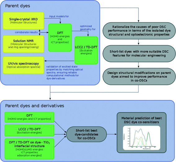
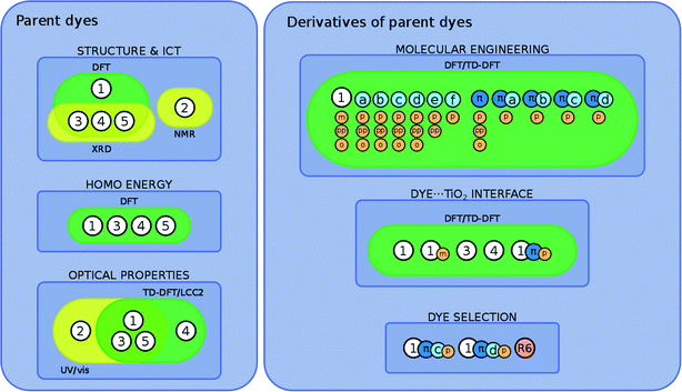
The overarching molecular engineering workflow used in this work (Fig. 3) therefore provides an internal experimental validation of the predicted co-DSC attributes, and allows the development of a molecular engineering strategy and, ultimately, the proposal of novel engineered co-sensitizers. Fig. 4 presents a summary of what type of experimental and/or computational tools were used to extract certain types of information from individual dyes. Therein, yellow and green boxes discriminate experimental and theoretical results, respectively.
2 Experimental and computational methods
2.1 Materials
Commercially available powders of 1–5 were purchased from Sigma Aldrich.2.2 Single-crystal X-ray diffraction
Single crystals of 3, 4 and the 5 (para) component of 5, suitable for X-ray diffraction analysis, were grown by slow evaporation of saturated ethanol solutions of 3–5 at room temperature. 5 is a mixture of two different chemicals (where the carboxylic acid group is either attached at position 5 (para) or 6 (meta) of the corresponding phenyl ring); yet the X-ray diffraction analysis revealed that only the isomer containing the carboxylic acid substituent at position 5 was present in the crystal structure. Despite numerous attempts, suitable crystals of 1, 2 or the 6-substituted (meta) component of 5 could not be obtained. Single-crystal diffraction data for 3, 4 and the 5-substituted (para) component of 5 were collected at 120 K, using a Rigaku Saturn 724+ CCD diffractometer, equipped with a Mo X-ray source (λMo-Kα = 0.71073 Å), SHINE Optics focusing device, and an Oxford Cryosystems CryostreamPlus open-flow N2 cooling device. Cell refinement, data collection, and integration were carried out using the Rigaku CrystalClear-SM Expert 2.0 software package,19 while absorption correction was applied using ABSCOR.20 Structures were solved by direct methods and refined by a full-matrix least-squares method on F2. All refinements were carried out in SHELXS.21 Hydrogen atoms of residual disordered water molecules were located using peaks in the Fourier difference map. The rest of the hydrogen atoms were positioned geometrically and refined as riding on their parent atoms. A full summary of crystallographic data and refinement details is reported in the associated deposition material.2.3 Nuclear magnetic resonance spectroscopy
All NMR measurements were carried out by the NMR service facility in the Department of Chemistry, University of Cambridge (UK). 1H and 13C{1H} NMR spectra for 2 (9.3 mM) were recorded in deuterated acetonitrile (CD3CN), dimethyl sulfoxide (DMSO-d6), or methanol (CD3OD) on a Bruker Avance 500 Cryo Ultrashield NMR spectrometer at room temperature. Chemical shifts (δ) are expressed in ppm relative to the internal standard tetramethylsilane (δ = 0 ppm). NMR spectra are shown in the ESI† S.2.2.4 UV/vis absorption and fluorescence spectroscopy
UV/vis absorption spectra for 1, 2, 3, and 5 (0.04 mM) were recorded in methanol (Fig. 6) on an Agilent Cary 300 UV-vis spectrophotometer. The limited sample quantities available for 4 did not allow the measurement of its UV/vis absorption spectrum. Peak molar extinction coefficients, ε, were calculated from the slope of the linear regression obtained from the measurement of peak absorbances using five different dye concentrations. Peak absorbance measurements for each concentration were repeated five times in order to eliminate potential systematic errors and obtain a standard deviation for the measurement.2.5 Computational studies
Electronic structures were calculated for 1, 3, 4, and both components of 5, as well as for their molecularly engineered derivatives. These studies included DFT and TD-DFT calculations carried out using Gaussian 09,22 as well as ab initio equation-of-motion coupled-cluster methods (EOM-CC)23 using Molpro24 and the local coupled-cluster response method (LT-DF-LCC2).25,26The structures of 3, 4 and the 5-substituted (para) component of 5, obtained from single-crystal X-ray diffraction analyses, were used as the initial input geometries for subsequent geometry optimizations using the PBE0 hybrid functional27–30 in combination with a 6-31G(p) basis set.31 Solvent effects were considered via the polarizable continuum model (PCM)32,33 in methanol. Positive vibrational frequencies were calculated for all dyes, indicating reliable ground-state structures.
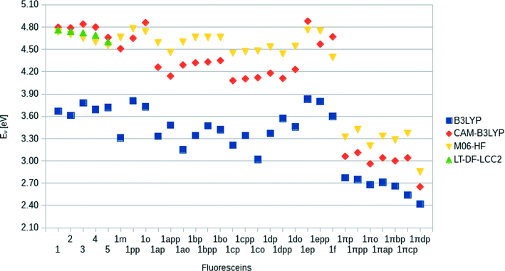
Single-point DFT energy calculations were performed on the optimized geometries in order to determine HOMO energies and spatial distributions of molecular orbitals. These calculations were performed at the PBE0/6-311+G(2d,p) level of theory34 in methanol using the PCM model. Orbitals were processed using cubgen22 and visualized in Avogadro35 (isovalues: 0.02). Difference-density plots between the squares of the HOMO and LUMO plots (LUMO2–HOMO2) were calculated for 1, 3, 4, and both components of 5 (isovalues: 0.0014) and all other dye derivatives (isovalues: 0.0007). Lowest-vertical excitation energies (EV) were obtained using TD-DFT calculations at the CAM-B3LYP/6-311+G(p) level of theory, including solvent effects. This functional was chosen after benchmark tests including B3LYP, CAM-B3LYP, and M06-HF functionals with LT-DF-LCC2 (cc-pVDZ basis set, including CIS solvent-shift effects) as a reference. LUMO energies were estimated from the sum of EV and EHOMO and the simulated UV/vis spectra were constructed by convoluting a Gaussian window function to the excitation energies, weighted by the oscillator frequencies.
The geometry of the dye⋯TiO2 interface was optimized using DFT calculations at the B3LYP level of theory and 6-31G* basis set in ethanol (PCM). Single-point energy calculations and excitation energies were generated using DFT and TD-DFT calculations, respectively, at the B3LYP level of theory and 6-311+G* basis set in ethanol (PCM).
3 Results and discussion
3.1 Establishing prerequisites for the molecular design of optimal dyes
This study of fluorescein dyes employed an analysis of their structural and optoelectronic properties, via a rational strategy aimed at increasing the performance of fluorescein-containing DSCs. The plan involved a preliminary experimental and computational study of a priori known fluorescein (parent) dyes 1–5. The implementation of computation in this preliminary study of the parent dyes overcame various experimental difficulties and limited sample availability, by complementing and corroborating the experimental results that were available (Fig. 4). The investigation of 1–5 was aimed at rationalizing the causes of their poor performance when used in DSC devices.16 The information gathered from the study was thence used to construct a set of molecularly-engineered fluorescein derivatives. The molecular design rules were aimed at: (i) ensuring chemical compatibility between the chemical derivatives, (ii) lowering EV by the extension of π-conjugation within the parent dye molecules, (iii) providing a suitably positioned anchoring group that favors electron injection and sterically allows adsorption of the dye onto the TiO2 surface.A subsequent analysis of the structural and optoelectronic properties of the in silico generated fluorescein derivatives, modeled in solution and at the dye⋯TiO2 interface, led to the short-listing of a handful of dyes from the large pool of molecularly-engineered derivatives. This short-listing procedure employed the following selection rules: (i) the dye must satisfy the energetic requirements of a DSC, i.e. the energy of the LUMO must exceed the conduction-band energy of TiO2 (ECB) and the energy of the HOMO must be lower than the redox energy of the electrolyte (Eredox). (ii) Short-listed dyes must exhibit a complementary absorption spectrum in order to increase light harvesting in a co-DSC.36,37 (iii) Optimal fluorescein derivatives should display high levels of electron density on the anchoring group, which favors electron injection and thus ideally prevents unwanted dye aggregation and electrolyte recombination.
Given the optical absorption of fluoresceins in the UV region of the electromagnetic spectrum, co-sensitization may also be able to solve a recurring issue caused by the I−/I3− electrolyte. The optical absorption of DSCs using I−/I3− electrolytes is reduced at ∼350–400 nm on account of the optical absorption window of the electrolyte. However, previous reports have demonstrated that this dip may be restored by co-sensitization of dyes absorbing at 300–400 nm.38,39 Using molecularly engineered fluoresceins for this purpose may moreover ensure chemical compatibility.
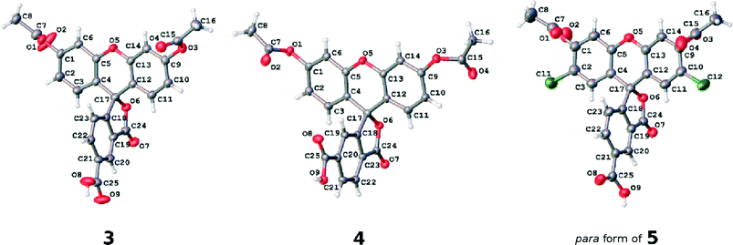 | ||
| Fig. 5 The asymmetric units of the crystal structures of parent dyes 3, 4 and the 5-substituted (para) component of 5. Atomic displacement parameters are drawn at the 50% probability level. | ||
The individual arene rings that are separated by this single-bonded intramolecular structural architecture nonetheless show π-conjugated behavior within themselves. They each bear a small degree of bond-length alternation; while this pattern is consistent, this trend does not span a difference of more than 0.03 Å, and so one can regard these arene rings as essentially delocalized structures. Such delocalization seems to be quite isolated from any chemical substituent effects, judging from its bond-length character being little affected by the presence of the anchoring group at different positions on the benzoxolane ring, from comparisons of the C18–C23 rings between 3 with 4 or the 5 (para) component of 5.
Since significant ‘push-pull’ intramolecular charge transfer, which extends across a good portion of the molecular chromophore, is regarded as a necessary criterion for a functional DSC dye, these findings show that the molecular architecture of these parent dyes in their lactone form would present poor applicability for DSC dye functionalization. However, if such fluorescein dyes could be reconfigured into their zwitterionic form, this would mitigate an interruption of the π-conjugated pathway across the molecule caused by the single-bonded internal character of the lactone form. Then, acceptor and donor moieties on opposing sides of the zwitterionic molecule would have the opportunity to become π-conjugated via the benzoxolane ring, exhibiting a quinoidal structure such that a C![[double bond, length as m-dash]](https://www.rsc.org/images/entities/char_e001.gif) C bond forms between this ring and the formally charged carbocation that joins the xanthene and benzoxolane moieties (cf.Fig. 2). π-conjugation that spans the xanthene and benzoxolane moieties would also enhance the ‘push-pull’ nature of the molecular chromophore to the extent that the associated optical absorption would then likely extend into the visible region of the electromagnetic spectrum. The COO– anion formed as a result of this zwitterion formation would also offer an extra anchoring option for dye⋯TiO2 binding at the DSC working electrode. Meanwhile, the anchoring group(s) could be connected easily to the intra-molecular charge transfer (ICT) pathway, thus affording good adsorption prospects for the dye at the dye⋯TiO2 interface that constitutes the DSC working electrode.
C bond forms between this ring and the formally charged carbocation that joins the xanthene and benzoxolane moieties (cf.Fig. 2). π-conjugation that spans the xanthene and benzoxolane moieties would also enhance the ‘push-pull’ nature of the molecular chromophore to the extent that the associated optical absorption would then likely extend into the visible region of the electromagnetic spectrum. The COO– anion formed as a result of this zwitterion formation would also offer an extra anchoring option for dye⋯TiO2 binding at the DSC working electrode. Meanwhile, the anchoring group(s) could be connected easily to the intra-molecular charge transfer (ICT) pathway, thus affording good adsorption prospects for the dye at the dye⋯TiO2 interface that constitutes the DSC working electrode.
Overall, these findings suggest that a way to molecular engineer fluorescein dyes which exist primarily in their zwitterionic form is needed, if one is to functionalize fluorescein dyes for effective DSC device application.
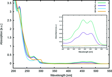 | ||
| Fig. 6 UV/vis absorption spectra of 1, 2, 3, and 5 in methanol (0.04 mM). The inset shows a magnification for the 280–540 nm region. | ||
Computational calculations (LT-DF-LCC2 with solvent-shift correction) on the cyclic lactone structural forms of 1 and 3–5 corroborated these experimentally-determined optical absorption findings, showing EV values in the UV-region of the absorption spectrum: 4.76 (1), 4.72 (3), 4.69 (4), and 4.60 eV (5), which correspond to the peak optical absorption wavelengths, λmax: 260 nm, 262 nm, 264 nm, 269 nm, respectively. EV values of 5 were calculated for both para and meta components of its mixture, reporting insignificant differences, within 0.03 eV. Despite the inclusion of an implicit solvent model (PCM, deemed necessary from previously established benchmarks17), computational efforts to model the zwitterionic isomer of 1–5, via both implicit and explicit solvent models, failed to produce geometrically stable structures. This suggests that the lactone configuration is markedly the most stable form of 1–5 in solution as well as in the solid state as judged by the aforementioned crystal structure analysis. Since dyes in DSC manufacture manifest in the solution state, and their lactone configuration bears limited ICT on account of the aforementioned interrupted π-conjugation, these parent dyes 1–5 will therefore exhibit poor optical performance in a DSC. Yet, as the crystal structure analysis concluded, if fluorescein dyes can be molecularly engineered to feature the zwitterionic form as their most stable configuration, they will likely portray optical absorption characteristics in the visible region of the electromagnetic spectrum, and thence could be applied as co-DSC dyes to afford good device performance. Having characterized the structural and optoelectronic attributes of 1–5, by forming a representative experimental and computational knowledge base of these fluorescein dyes, this molecular engineering goal was therefore set.
3.2 Molecular engineering of DSC dyes
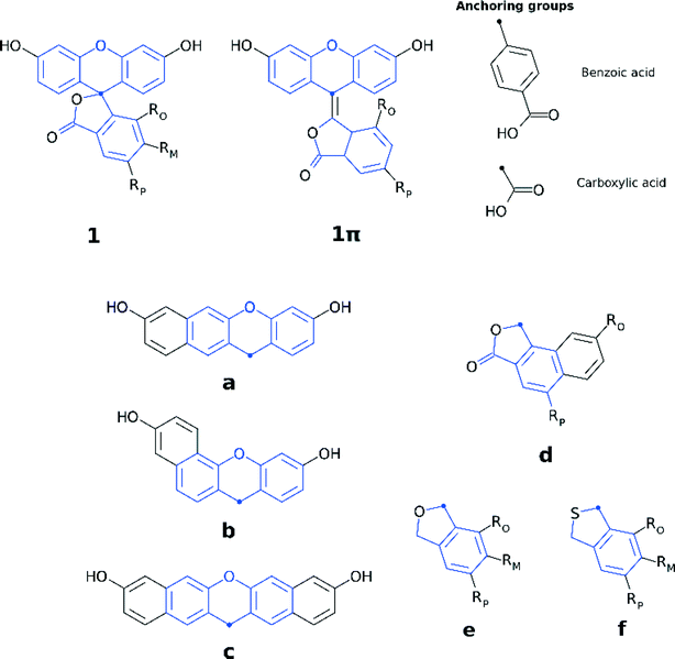
Three sets of structural modifications can be distinguished and are labeled XYZ: (i) extension of the π-conjugation through the xanthene and benzoxolane moieties in order to simulate the formation of zwitterionic isomers (X); (ii) modifications to the xanthene or benzoxolane moieties, involving addition of rings or substitution of core atoms (Y); and (iii) addition of carboxylic or benzoic acid anchoring groups at ortho, meta, or para position (Z). These sets of modifications can be combined, in order to achieve greater control over the optoelectronic properties of the dyes and the creation of a wide range of different dyes. The parent dyes showed similar optoelectronic properties (cf. section 3.1.2), rendering 1–5 equally good potential candidates for molecular engineering. Given the similar optoelectronic properties, structural modifications were carried out on 1, as its relatively small size affords the most favorable ratio between the extent of modifications and computational cost.
The three sets of structural modifications for 1 are: (i) the addition of a single arene ring (benzannulation) of the xanthene moiety at two different positions (XaZ and XbZ), twofold benzannulation of the xanthene moiety (XcZ), benzannulation of the benzoxolane moiety (XdZ), removal of the double-bonded oxygen from the benzoxolane moiety (XeZ), substitution of oxygen with sulfur in the benzoxolane moiety (XfZ); (ii) extension of the π-conjugation between the xanthene and benzoxolane moiety (1πYZ); (iii) substitution of the carboxylic acid anchor at the para-position (XYp), substitution of the benzoic acid anchor at the para-position (XYpp), substitution of the carboxylic acid anchor at the ortho-position (XYo), substitution of the carboxylic acid anchor at the meta-position (XYm). A complete list of molecular engineering combinations is shown in Fig. 4, while Fig. 7 shows the chemical structure schematics of the engineered derivatives.
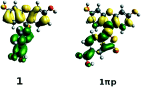
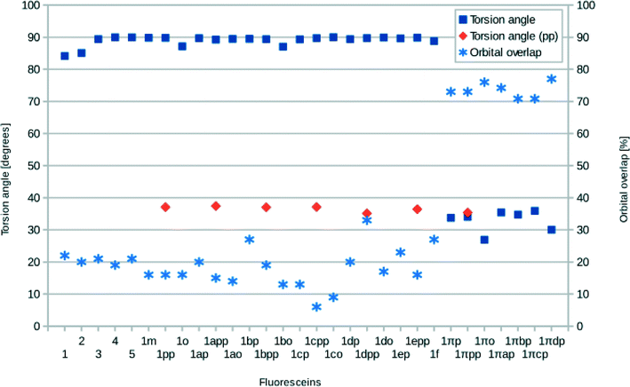
The structures of all derivatives converged to a stable geometry. Torsion angles of ∼90° were observed between the formerly xanthenes and benzoxolane moieties, except for 1πYZ, which exhibited a substantially smaller torsion angle of ∼30°. This exception occurs presumably because of the change from sp3 to sp2 hybridization at the juncture of xanthene and benzoxolane moieties that is enforced by adding a double bond in this in silico chemical derivation (the π signature as labeled). There is a corresponding increase in the molecular orbital overlap from 1YZ (20%) to 1πYZ (∼75%; Fig. 10). The analysis of the Kohn–Sham orbitals clearly showed different electronic structures for derivatives exhibiting different levels of conjugation. Derivatives of 1 exhibit HOMOs and LUMOs located on the formerly benzoxolane and xanthene units, respectively, while derivatives of 1π revealed overlapping HOMOs and LUMOs at the formerly xanthene and benzoxolane moieties (Fig. 8). Even though a separated HOMO/LUMO orbital arrangement is usually more favorable for unidirectional ICT, the resulting lowest excitation energies constitute a more important discriminator for the short-listing of derivatives. Furthermore, 1π exhibited high electron density on the anchoring group, which is indicative of an overall anisotropic ‘push-pull’ charge movement towards the benzoxolane acceptor unit. Charge separation is further considered in §3.3, which analyzes the modeled dyes at the dye⋯TiO2 interface and shows that it is a more prominent feature in the dye-adsorbed composite structure. This is as expected since this composite represents the DSC working electrode.
Following the same trend, the low-lying vertical excitation energies, EV, between derivatives of 1 and 1π differ substantially. The increased π-conjugation in 1πYZ resulted in a marked shift in EV (Fig. 9). While in derivatives of 1YZ the energy decreased by ∼0.7 eV, shifts of ∼1.3–1.9 eV were observed for derivatives of 1πYZ. These results were consistently observed for all functionals employed in the calculations.
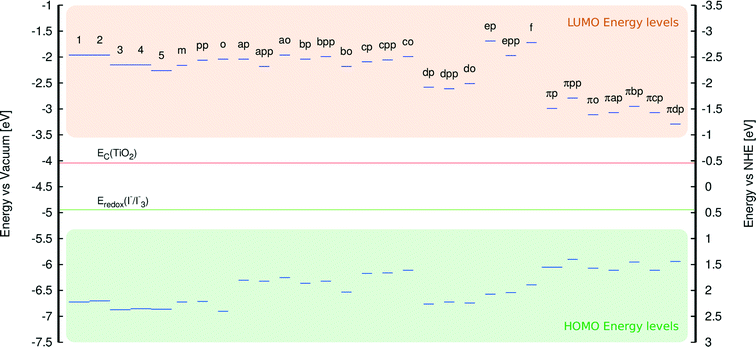
An analysis of the HOMO and LUMO energy levels revealed that all examined dyes satisfy the energetic conditions required for the use in DSCs, which were stipulated in section 3.1. This analysis is borne out by Fig. 11 which shows that the LUMO energies of all dyes are well above the conduction band edge of TiO2, while their HOMO energies are substantially below the energy corresponding to the redox electrolyte.
3.3 Modeling the dye⋯TiO2 interface
The behavior of fluoresceins at the TiO2 surface was examined by DFT and TD-DFT calculations at the dye⋯TiO2 interface using a (TiO2)9 cluster model. Owing to the higher computational cost of this study, compared with calculations on the isolated dyes, a subset of dyes was selected for these interfacial studies, based on the convergence criteria of the calculations. Previous studies had identified the cluster (TiO2)9 as a good compromise between computational cost and accuracy,41–43 and so this cluster was also used in this work (see ESI† S.4).Three different types of anchoring modes were analyzed in this study: monodentate (m), bidentate bridging (bb), and bidentate chelating (bc). Calculations involved dyes 1 (m, bc), 3 (bb), 4 (m, bc), 1m (m, bc), and 1πp (bc). Calculations involving 2, 5, and the 1Z dyes (except for 1m) did not produce a satisfactory optimized geometry to perform further calculations, whilst 1YZ dyes were too large to be included in this calculation. Owing to the computational cost of this study, only 1πp was selected from the 1πYZ dyes, due to its size and suitable anchoring group. The adsorption energies were obtained according to:
| Eads = Edye + ETiO2 − Edye/TiO2, | (3) |
The results did not reveal any significant changes in the structural and optoelectronic properties relative to the calculations for the molecular dyes in solution. However, a notable change was observed in the molecular orbital overlap index, Λ, which decreased (0–10%) relative to the isolated dyes in solution (13–23%). Such low orbital overlap values for the dye⋯TiO2 composites indicate successful electron injection during the excitation process (Fig. 12). Whilst EV values remained constant, significantly different oscillator strengths were observed for 1πp⋯TiO2 compared to 1, 3, 4, and 1m (see ESI† S.4). Average adsorption energies of −0.5 (m), −0.3 (bb), −1.9 (bc) were calculated, showing that the bridging chelating mode should represent the most stable anchoring mode for this set of dyes, regardless of the dye used.
 | ||
| Fig. 12 Molecular orbitals of 1πp attached to a (TiO2)9 cluster. Excited states show a deposition of charge on the TiO2 cluster, which is consistent with successful electron injection. | ||
3.4 Determining a suitable combination of dyes for co-DSCs
On the basis of the molecular engineering results from the dye solution and dye⋯TiO2 interface models, we tried to identify the best dye pairs for potential applications in co-sensitized DSCs.The selection process thereby considered all the requirements defined at the beginning of the study. For example, all dyes containing a benzoic acid anchoring group were excluded, as their EV values did not significantly differ from those of their parent dyes. Furthermore, the size of the benzoic acid anchoring group might negatively influence the anchoring process by reducing the stability. Dyes with the anchoring group at the ortho position (XYo) were also excluded on account of their lower absorption intensity and small EV changes.
Conversely, enhanced optical absorption intensities were observed for 1cp and 1πcp, which contain twofold benzannulated xanthene moieties, while 1πdp showed the lowest EV value of all the remaining derivatives. Furthermore, 1π dyes also presented excitation energies in the UV region of the electromagnetic spectrum, i.e. leading towards panchromatic optical absorption.
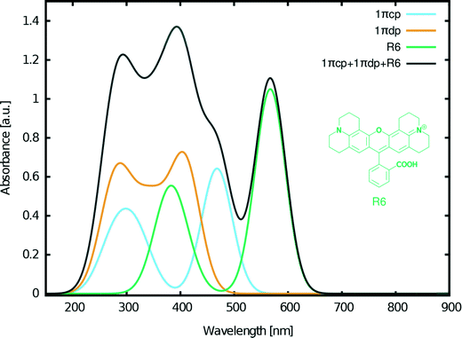
Despite these positive results of our molecular engineering efforts in designing fluorescein dyes that exhibit optical absorption in the visible as well as UV regions of the electromagnetic spectrum, a significant portion of the solar emission spectrum remained uncovered by any combination of the examined fluoresceins. However, this part of the spectrum (>500 nm) can be covered by the closely related rhodamine dye R6 (Fig. 13) which we previously investigated via another molecular engineering study.17 The chemical structure of rhodamines is very similar to that of fluoresceins, thus ensuring chemical compatibility. Furthermore, our previous studies on this dye in combination with 2 showed synergistic adsorption of both dyes onto a TiO2 substrate when co-sensitized for a DSC via either cocktail or sequential device fabrication methods.17
Based on these considerations, the following three dyes were selected for DSC co-sensitization: 1πcp + 1πdp + R6 (Fig. 13). The superimposed absorption spectrum that emulates the optical range of a co-DSC device which uses these three dyes (Fig. 13, black curve), evidences a panchromatic optical absorption range from ∼200–650 nm. To this end, the contribution of R6 in further extending the light harvesting of the fluorescein-designed co-DSCs into the visible part of the optical spectrum is significant. Fig. 13 also shows high optical absorption at ∼400 nm, thereby evidencing that this dye combination can be used to recover the dip in the absorption spectrum that is known to occur when forming the full co-DSC device owing to the I−/I3− electrolyte.38,39
4 Conclusions
A set of fluorescein dyes (1–5) has been examined for their suitability in potential co-sensitized DSC applications. In order to determine their structural and optoelectronic properties, the parent dyes were examined experimentally where possible, via X-ray diffraction (3–5), nuclear magnetic resonance spectroscopy (2) and/or UV/vis absorption spectroscopy (1–3, 5). Information that was not attainable by experiment was obtained via quantum chemical calculations. This synergistic application of experimental and computational methods also helped to validate the theoretical foundation by which the electronic structures of the molecularly-engineered, in silico generated, dyes were predicted. To this end, having used the findings of 1–5 to define the molecular design rules needed to create fluorescein-based DSC dyes, a set of 26 molecularly engineered dyes, based on the core structure of 1, with different levels of π-conjugation was calculated by: (i) adding molecular fragments to the xanthene and benzoxolane moieties of 1 (1Z, 1aZ, 1bZ, 1cZ, 1dZ, 1eZ, and 1fZ), (ii) extending the π-conjugation between these two moieties (1πZ, 1πaZ, 1πbZ, 1πcZ, and 1πdZ), (iii) adding anchoring groups at different positions (XYp, XYpp, XYo, and XYm). Their structures and optoelectronic properties were examined by DFT and TD-DFT calculations, which furnished HOMO and LUMO energy levels, molecular orbital shapes, and vertical excitation energies, Ev. A subset of these in silico generated dyes were short-listed for further analysis whereby changes were explored in their structure, optical and electronic properties upon adsorption of the dye onto a TiO2 surface, since the resulting dye⋯TiO2 interface represents the DSC working electrode. The associated structural models for these calculations involved the dyes being anchored onto a (TiO2)9 cluster in various binding configurations; the bridging bidentate form was found to be the most stable as is generally expected for DSC dyes.3,44Additional molecular design criteria were then defined in order to predict which of these fluorescein dyes might be suitable for co-DSC applications. These criteria envisage the generation of chemically compatible dyes, with extended π-conjugation for lower absorption energies and suitable anchoring locations for enhanced electron injection. Based on the objectives required (suitable HOMO/LUMO energy levels, complementary absorption spectra, and the regeneration of the dip in optical absorption spectrum that occurs when the DSC device is formed owing to the redox couple), the accumulated data from this study and the results from a previous molecular-engineering investigation on a closely related dye family, rhodamines,17 three dyes were selected to be used in concert in a co-DSC: 1πcp, 1πdp and the rhodamine dye, R6. This produced an overarching spectrum that is panchromatic across the optical absorption range ∼200–650 nm. The three dyes involved showed complementary optical absorption spectra to each other and are chemically compatible. The two derivatives of 1π displayed bathochromic shifts of 1.3 eV (100 nm) and a 1.9 eV (170 nm), respectively, while the rhodamine dye improved the range of optical absorption in the visible region of the electromagnetic spectrum. Furthermore, the concerted use of these three dyes produced an overall optical absorption profile that features a peak at ∼400 nm, which is in the region of I−/I3− electrolyte absorption, so co-DSCs bearing these dyes could regenerate this otherwise dip in DSC device optical absorption.
More generally, we have shown that molecular engineering provides a cheap way of predicting new efficient chromophores for co-DSC applications. The “bottom up” approach used in this and previous studies14–16 complements the “top down” approach, which envisions large-scale data mining for suggesting new classes of DSC dyes.45 The necessity for a molecular engineering approach lies in the flexibility of this method to predict dyes for a variety of purposes by refunctionalizing them for a new type of device application. By establishing the prerequisite molecular design rules, different molecular properties can be targeted and are easily tested for selection. Fine-tuning is convenient to adapt dyes to new DSC niche applications such as “smart windows” and, particularly, co-sensitization. This study has shown that predictive methods such as molecular engineering offer a systematic approach to the discovery of highly efficient DSC dyes.
Acknowledgements
G. P. thanks the EPSRC for a DTA Studentship (Reference: EP/K503009/1). J. M. C. is grateful to the 1851 Royal Commission for the 2014 Design Fellowship, and Argonne National Laboratory where work done was supported by DOE Office of Science, Office of Basic Energy Sciences, under Contract No. DEAC02-06CH11357. The Bragg Institute at ANSTO is gratefully acknowledged for funding (for P. G. W.). All authors thank the EPSRC UK National Service for Computational Chemistry Software (NSCCS) and acknowledge contributions from its staff in supporting this work.Notes and references
- S. Shafiee and E. Topal, Energy Policy, 2009, 37, 181 CrossRef.
- D. J. Hofmann, J. H. Butler and P. P. Tans, Atmos. Environ., 2009, 43, 2084 CrossRef CAS.
- A. Hagfeldt, G. Boschloo, L. Sun, L. Kloo and H. Pettersson, Chem. Rev., 2010, 110, 6595 CrossRef CAS PubMed.
- Z. Xie, et al. , Chem. Commun., 2014, 50, 608 RSC.
- C. Bechinger, S. Ferrere, A. Zaban, J. Sprague and B. A. Gregg, Nature, 1996, 383, 608 CrossRef CAS.
- K.-S. Ahn, S. J. Yoo, M.-S. Kang, J.-W. Lee and Y.-E. Sung, J. Power Sources, 2007, 168, 533 CrossRef CAS.
- B. O'Regan and M. Grätzel, Nature, 1991, 353, 737 CrossRef.
- A. Yella, et al. , Science, 2011, 334, 629 CrossRef CAS PubMed.
- K. Kakiage, et al. , Chem. Commun., 2015, 51, 15894 RSC.
- M. Kimura, H. Nomoto, N. Masaki and S. Mori, Angew. Chem., 2012, 124, 4447 CrossRef.
- A. Mishra, M. K. R. Fischer and P. Bäuerle, Angew. Chem., Int. Ed., 2009, 48, 2474 CrossRef CAS PubMed.
- M. Cheng, X. Yang, J. Li, F. Zhang and L. Sun, ChemSusChem, 2012, 6, 70 CrossRef PubMed.
- G. D. Sharma, M. S. Roy and S. P. Singh, J. Mater. Chem., 2012, 22, 18788 RSC.
- S. L. Bayliss, J. M. Cole, P. G. Waddell, S. McKechnie and X. Liu, J. Phys. Chem. C, 2014, 118(26), 14082–14090 CAS.
- F. A. Y. N. Schröder, J. M. Cole, P. G. Waddell and S. McKechnie, Adv. Energy Mater., 2015, 5, 1401728 CrossRef.
- G. Pepe, J. M. Cole, P. G. Waddell and S. McKechnie, Mol. Syst. Des. Eng., 2016, 1, 86 Search PubMed.
- G. Pepe, J. M. Cole and P. G. Waddell, Mol. Syst. Des. Eng., 2016 10.1039/C6ME00075D.
- H. Zheng, X.-Q. Zhan, Q.-N. Bian and X.-J. Zhang, Chem. Commun., 2013, 49, 429 RSC.
- CrystalClear-SM Expert, 2.0 Software Package, 2009 Search PubMed.
- A. Messerschmidt, M. Schneider and R. Huber, J. Appl. Crystallogr., 1990, 23, 436 CrossRef CAS.
- G. M. Sheldrick, Acta Crystallogr., Sect. A: Found. Crystallogr., 2007, 64, 112 CrossRef PubMed.
- M. J. Frisch, et al., Gaussian09 Revision D.01, Gaussian Inc., Wallingford CT, 2009 Search PubMed.
- J. F. Stanton and R. J. Bartlett, J. Chem. Phys., 1993, 98, 7029 CrossRef CAS.
- H.-J. Werner, et al., MOLPRO, version 2012.1, a package of ab initio programs, 2012 Search PubMed.
- D. Kats, T. Korona and M. Schutz, J. Chem. Phys., 2006, 125, 104106 CrossRef PubMed.
- D. Kats and M. Schutz, J. Chem. Phys., 2009, 131, 124117 CrossRef PubMed.
- B. Hammer, L. Hansen and J. Norskov, Phys. Rev. B: Condens. Matter Mater. Phys., 1999, 59, 7413 CrossRef.
- J. P. Perdew, K. Burke and M. Ernzerhof, Phys. Rev. Lett., 1996, 77, 3865 CrossRef CAS PubMed.
- J. P. Perdew, M. Ernzerhof and K. Burke, J. Chem. Phys., 1996, 105, 9982 CrossRef CAS.
- C. Adamo and V. Barone, Chem. Phys. Lett., 1998, 298, 113 CrossRef CAS.
- P. C. Hariharan and J. A. Pople, Theor. Chim. Acta, 1973, 28, 213 CrossRef CAS.
- D. M. Chipman, J. Chem. Phys., 2000, 112, 5558 CrossRef CAS.
- S. Miertus, E. Scrocco and J. Tomasi, Chem. Phys., 1981, 55, 117 CrossRef CAS.
- R. Krishnan, J. S. Binkley, R. Seeger and J. A. Pople, J. Chem. Phys., 1980, 72, 650 CrossRef CAS.
- M. D. Hanwell, et al. , J. Cheminf., 2012, 4, 17 CAS.
- W. Wu, F. Meng, J. Li, X. Teng and J. Hua, Synth. Met., 2009, 159, 1028 CrossRef CAS.
- A. Burke, L. Schmidt-Mende, S. Ito and M. Grätzel, Chem. Commun., 2007, 234–236 RSC.
- L. Han, et al. , Energy Environ. Sci., 2012, 5, 6057 CAS.
- N. Shibayama, H. Ozawa, M. Abe, Y. Ooyama and H. Arakawa, Chem. Commun., 2014, 50, 6398 RSC.
- F. H. Allen, et al. , J. Chem. Soc. Dalton Trans., 1987, 12 Search PubMed.
- R. S. de Armas, et al. , J. Chem. Theory Comput., 2010, 6, 2856 CrossRef PubMed.
- R. S. de Armas, M. A. S. Miguel, J. Oviedo and J. F. Sanz, Phys. Chem. Chem. Phys., 2012, 14, 225 RSC.
- R. S. de Armas, M. A. San-Miguel, J. Oviedo, A. Marquez and J. F. Sanz, Phys. Chem. Chem. Phys., 2011, 13, 1506 RSC.
- L. Zhang, J. M. Cole and C. Dai, ACS Appl. Mater. Interfaces, 2014, 6, 7535 CAS.
- J. M. Cole, et al. , Phys. Chem. Chem. Phys., 2014, 16, 26684 RSC.
Footnotes |
| † Electronic supplementary information (ESI) available. See DOI: 10.1039/c6me00075d |
| ‡ Current address: School of Chemistry, Newcastle University, Newcastle upon Tyne, NE1 7RU, UK. |
| This journal is © The Royal Society of Chemistry 2016 |

