
New insights into the complex regulation of the glycolytic pathway in Lactococcus lactis. I. Construction and diagnosis of a comprehensive dynamic model
Sepideh
Dolatshahi
,
Luis L.
Fonseca
and
Eberhard O.
Voit
*
Department of Biomedical Engineering, Georgia Institute of Technology, Atlanta, GA 30332, USA. E-mail: sepideh@gatech.edu; llfonseca@gatech.edu; eberhard.voit@bme.gatech.edu
First published on 6th November 2015
Abstract
This article and the companion paper use computational systems modeling to decipher the complex coordination of regulatory signals controlling the glycolytic pathway in the dairy bacterium Lactococcus lactis. In this first article, the development of a comprehensive kinetic dynamic model is described. The model is based on in vivo NMR data that consist of concentration trends in key glycolytic metabolites and cofactors. The model structure and parameter values are identified with a customized optimization strategy that uses as its core the method of dynamic flux estimation. For the first time, a dynamic model with a single parameter set fits all available glycolytic time course data under anaerobic operation. The model captures observations that had not been addressed so far and suggests the existence of regulatory effects that had been observed in other species, but not in L. lactis. The companion paper uses this model to analyze details of the dynamic control of glycolysis under aerobic and anaerobic conditions.
1 Introduction
The results of most experiments in biology are snapshots that shed light on one or a few aspects of a phenomenon of interest. These snapshots are usually singular, sometimes comparative, contrasting two different conditions, or increasingly in the form of time series that represent cellular responses following a stimulus. The snapshots may be very complicated, for instance, by consisting of detailed images, capturing the expression levels of whole genomes, or revealing thousands of peaks in a proteomic or metabolomics mass spectrogram. Yet, each snapshot is separately frozen in time, and inferring a comprehensive cellular strategy from these data requires an additional and genuinely different cognitive process in the form of a conceptual or formal model. Particularly well suited for this purpose are dynamic models, which have the unparalleled capacity of permitting the weaving of multiple, often heterogeneous data into chains of events with which a cell or organism responds to a change in its milieu.This article and its companion1 describe this process of connecting snapshots into cohesive storylines within the context of a complex task that the bacterium Lactococcus lactis must solve. Namely, the bacterium has to survive periods of starvation and at the same time be optimally positioned to take up substrate once it becomes available again, which is not a trivial matter, as we will discuss. Expressed differently, it must reach a “ready-to-respond” state while substrate is running out. The goal of these two papers is to decipher through dynamical modeling how the cells coordinate a complex control program to ensure this state. The first paper focuses on the construction of the model, while the second paper1 utilizes this model to shed light on the complex regulatory program, with which the organism controls glycolysis and ensures a viable ready-to-respond state.
The construction of a dynamic model of the type envisioned here has become possible with the recent availability of comprehensive time series data that characterize the dynamics of genomic, proteomic, metabolic, and physiological responses. Of particular interest for biochemical pathway modeling is the availability of relatively dense time profiles of metabolites through measurement techniques such as mass spectrometry (MS2,3), nuclear magnetic resonance (NMR4), protein kinase phosphorylation, or mass cytometry (CyTOF5). These data contain valuable, but implicit, information about the structure and dynamics of the biological system under study and permit the use of top-down modeling approaches. These approaches consist of minimizing the residual error between the measured data, i.e., the time profiles, and the assumed model, which typically consists of a system of nonlinear ordinary differential equations (ODE) that are to be parameterized.6
In an effort to build a kinetic-dynamic model using time-series data, the most challenging steps are the identification of suitable mathematical formats for all flux representations and the estimation of their unknown kinetic parameters. Central to these tasks is the methodology of dynamic flux estimation (DFE).7
In contrast to previous models, which captured the dynamics of single datasets (e.g., ref. 8 and 9), this paper describes a single aggregate model that combines three datasets for different input glucose concentrations. This single model enables the assessment of several intriguing observations, which to date had not been explained convincingly.
A particular observation that has been puzzling for a long time is the following: if glucose is supplied to the medium in different amounts, one would expect a corresponding increase in the peak level of the downstream metabolite fructose-1,6-bisphosphate (FBP). However, the data clearly show that the peak concentration is largely independent of the external glucose concentrations. Specifically, comparing the different series of experimental results with increasing glucose concentrations, the FBP accumulation shows a progressively more noticeable plateau, whose duration, but not height, varies with substrate availability (Fig. 1). A previous model for aerobic conditions9 was able to fit glycolytic data for a single glucose concentration of 20 mM, but extrapolating the model toward different glucose inputs, such as 40 or 80 mM, predicted almost a doubling or quadrupling of the FBP peak height, which is in obvious contrast to the experimental measurements under anaerobic conditions. Here, we analyze the situation in detail and extract constraints that the model and its parameters must satisfy to yield a good fit to the data.
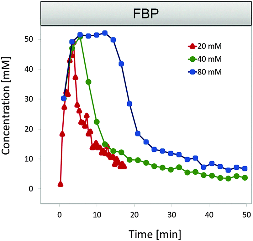 | ||
| Fig. 1 FBP data for three external glucose concentrations under anaerobic conditions. The peak level appears to be independent of the available substrate concentrations. One also notes that FBP does not vanish completely and instead maintains some residual concentration. Data summarized from ref. 12 and 13. | ||
Throughout the analysis here and in the companion paper, such sometimes non-intuitive observations will be discussed, and the roles of numerous precisely timed regulatory mechanisms will be explained through controlled simulations with and without such mechanisms.
2 Data
The time series data on which this study is based were collected through in vivo nuclear magnetic resonance (NMR) spectroscopy10 from L. lactis cells that were initially starved and then offered a pulse of labeled glucose at time zero. These data contain extensive information about the structure, dynamics and regulation of the organism's metabolism, which in this method is essentially unadulterated by cell disruption, purification, centrifugation or other harsh experimental methods. The technical aspects of the non-invasive determination of the concentrations of the intracellular pools of intermediate metabolites using in vivo NMR (13C- and 31P-NMR) experiments were thoroughly discussed in ref. 10–12. A brief summary of the data follows below.The measured time series include the external concentrations of glucose and of the end product lactate in the medium, along with several of the more abundant intermediate metabolites, namely glucose 6-phosphate (G6P), fructose 1,6-bisphosphate (FBP), phosphoenol pyruvate (PEP), 3-phosphoglycerate (3PGA). The time series reflect three experiments performed with 20, 40, or 80 mM of glucose input, respectively. Additional time series are available for some ubiquitous cofactors, such as NAD+ and NADH, which are detectable with somewhat limited detection capability due to the required NMR acquisition time.12 Finally, the level of NTP was measured using 31P-NMR. The datasets used for modeling are summarized in Table 1.
| Experiment | Condition | Technique | Metabolites measured | Time interval |
|---|---|---|---|---|
| (1) 20 mM [6-13C] glucose |
Anaerobic
pH = 6.5 |
13C-NMR | glc, G6P, FBP, 3PGA, lac | 30 s |
| (2) 40 mM [1-13C] glucose and [5-13C] nicotinate |
Anaerobic
pH = 6.5 |
13C-NMR
31P-NMR |
glc, FBP, 3PGA, PEP, lac, NAD+, NADH
ATP, Pi |
2.2 min
2.75 min |
| (3) 80 mM [1-13C] glucose and [5-13C] nicotinate |
Anaerobic
pH = 6.5 |
13C-NMR
31P-NMR |
glc, FBP, 3PGA, PEP, lac, NAD+, NADH
ATP, Pi |
2.2 min
2.75 min |
In Experiment 1, 20 mM of [6-13C] glucose were supplied to the cell suspension, and time series of concentrations were recorded for glucose, G6P, FBP, 3PGA, and lactate with a resolution of 30 seconds. In Experiments 2 and 3, cells were supplied beforehand with labeled [5-13C] nicotinic acid, a precursor of NADH, thus ensuring this pool to be 100% labeled.12 To start the in vivo NMR experiments, cells were supplied with 40 and 80 mM of [1-13C] glucose, respectively, and time series of glucose, FBP, PEP, 3PGA, lactate, NAD+ and NADH were recorded. The time resolution in these experiments was 2.2 minutes, which was needed to accommodate the determination of NAD+ and NADH with a reasonable signal-to-noise ratio. In a separate, comparable experiment, cellular metabolism was investigated with 31P-NMR, which allowed the measurement of NTP (mostly ATP), Pi and pH with a time resolution of 2.75 min. Usage of [1-13C] glucose prevents the determination of G6P in these datasets, due to the similarity in chemical shifts of [1-13C] glucose and [1-13C] G6P. However, some measurements of G6P are available from experiments with 20 mM [6-13C] glucose. Although the data described above exhibit experimental noise and are incomplete, with some metabolites or time points missing in each set, they are as good as a modeler can presently hope for. Duplicates are available for Experiments 1 and 2. These replicate datasets have a highly similar behavior to the modeled datasets, which shows that the data obtained with these NMR methods are highly reproducible. The additional datasets are not used for the modeling for the same reason of similarity and the fact that they contain time series data for fewer intermediate metabolites.
Under the given experimental conditions, cells are not able to synthesize ATP (nor ADP) de novo, because they are suspended in phosphate buffer and supplied only with glucose, which is insufficient for L. lactis to grow. Once the culture is harvested and washed prior to the NMR experiment, the total amount of ATP + ADP remains constant. This fact enables us to infer ADP from the ATP data where these are available (for Experiments 2 and 3), which is beneficial for the initial parameter estimation. By the same token, the cells do not synthesize proteins and they do not alter the expression of their genes.
In all datasets, the concentrations of 3PGA and PEP are highly covariant, due to the fact that these two metabolites can be converted into 2PGA by two enzymatic steps (phosphoglycerate mutase and enolase). These reactions are fast and reversible with equilibria that favor 3PGA and PEP,14–16 thus maintaining 2PGA in a concentration range below the in vivo13C-NMR detection level. Since this covariance is maintained even during high glycolytic flux, we decided to aggregate these two pools into one dependent variable (X4). Nonetheless, we are still able to calculate the concentration of each intermediate from the constant proportionality of ∼0.6444 (3PGA/PEP).
The data seem to indicate an apparent absence of PEP and FBP at the beginning of the experiment. However, these metabolites are present, but just not labeled initially and therefore missed by the NMR detection. The concentrations of these metabolites were measured in a control experiment,11 supporting the reasonable assumption that the cells re-enter a state of starvation at the end of the experiment and that the residual values of now labeled PEP and FBP constitute a state that is similar to the state at the beginning of the experiment. This conjecture is further supported by a tandem experiment in which glucose was presented twice after periods of starvation.10
3 Model design
Generically, a mathematical model of a metabolic system consists of a system of ordinary differential equations with three components: (1) a stoichiometric matrix; (2) a vector of fluxes; and (3a) the functional forms of these fluxes and (3b) their corresponding parameter values. The stoichiometric matrix represents the essentially time-invariant wiring diagram of the pathway and shows which fluxes enter or leave each pool. It is often assumed to be known from biochemical experimentation, and the results of uncounted such studies are collected in databases like KEGG17 and MetaCyc.18 Kinetic details and regulatory features are represented by parameters that are incorporated in appropriate functional forms representing the fluxes.The structure of the pathway at hand is presented in Fig. 2. A dynamic model for a similar type of experiments with 20 mM external glucose, but under aerobic conditions, was developed previously.9 We started out with this model attempting to adjust it toward anaerobic conditions by including additional regulatory mechanisms from the biochemical literature, accounting for ubiquitous metabolites including NAD+, NADH, ATP, and ADP as dependent variables, and making other necessary adjustments to the pathway based on biological literature. Unfortunately, the final task of parameter estimation did not succeed when the three datasets were to be captured simultaneously. Thorough analysis suggested a revisiting of the assumptions that were made originally regarding the pathway regulation and of the subtle, but genuine differences between operation under aerobic and anaerobic conditions. The amendments and alterations that became necessary will be explained in the following sections.
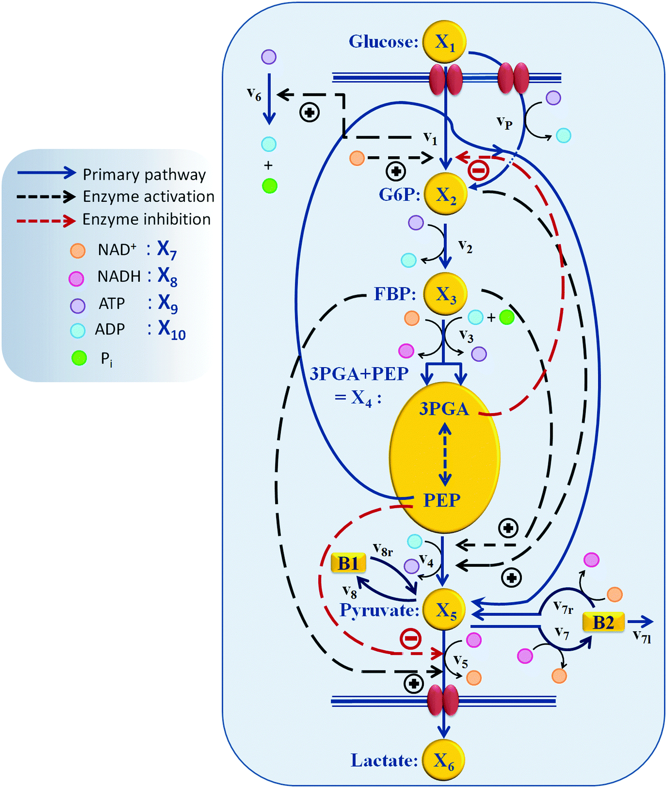 | ||
| Fig. 2 Model structure of the glycolytic pathway in L. lactis. Of particular importance are the PTS mechanism, which uses PEP for the initial phosphorylation of glucose, and several regulatory signals, indicated here with dashed arrows. | ||
3.1. Dynamic flux estimation
The numerical characterization of an appropriate metabolic pathway model consists of the identification of mathematical formats for all process steps, and the estimation of optimal numerical parameter values in these process formulations. The determination of optimal representations for the processes in the model is by no means trivial, as no guidelines are available, but it is very important, because inadequate representations, even if they fit a target dataset, run the risk of error compensation among flux terms and of incurring problems during extrapolations.7,19,20We use for this identification step dynamic flux estimation (DFE).7 In a nutshell, DFE works in the following manner. First, the time courses of all metabolites are smoothed, so that slopes can be estimated. These slopes are substituted for the derivatives on the left-hand sides of the ordinary differential equations (ODEs) at many time points, thereby replacing each ODE with a set of algebraic equations. At each time point, the algebraic equations can be solved by matrix inversion, with the help of pseudo-inverses, or with auxiliary methods.21–24 Combining these solutions yields graphical or numerical representations of all fluxes, either plotted against time or against the variables on which they depend. These representations can secondarily be fitted with functions that might be appropriate, which directly permits an assessment of the appropriateness and quality of the chosen functions.
The main attraction of DFE is the fact that this method does not presuppose a functional form for any of the flux representations. This feature allows us to test in an objective manner whether particular functions, such as power-laws, Michaelis–Menten rate laws, or Hill functions, are capable of appropriately modeling a specific flux, or if other formulations should be considered. Importantly, careful analyses of all fluxes in this manner may suggest the existence of regulatory signals that had been missing from the assumed pathway structure. Such a suggestion corresponds to a novel hypothesis that is in principle testable with lab experiments and may lead to biological discoveries. An example is the glucose uptake process, which the companion paper1 discusses in detail. In this case, slopes can directly be obtained through numerical differentiation of the uptake profile. The result of the first phase of DFE, which is independent of any model assumptions, reveals that this process must be regulated and suggests candidate regulators. These insights are used to refine the model construction.
In addition to its diagnostic capacities, DFE allows for a much more efficient parameter estimation strategy in terms of computation costs that are associated with the integration of ODEs and with global optimization. Namely, the parameters can be estimated one flux at a time. This decoupling is very advantageous, as one uses explicit functions, thereby avoiding—or at least reducing—the need to integrate ODEs numerous times, and because there is no risk of error compensation among terms or equations.
The first, model-free phase of DFE requires the estimation of slopes from the metabolic time course data. Several methods have been proposed for this purpose (e.g., see discussion in ref. 25); as a further alternative, a smoothing algorithm was introduced in ref. 26 based on the wavelet transforms that ensures conservation of mass.
Not all processes in the model can be directly assessed with DFE because; for instance, some time courses are missing. Nonetheless, DFE provides a beneficial initial step that significantly constrains the subsequent parameter estimation.
Our generic strategy thus is the following. As far as feasible, we use DFE to identify candidates for possibly missing regulatory effects. Next, we computationally select reasonable functional forms in a process that is ideally guided by biology known from the literature. Then we use DFE to obtain starting points for as many parameters as possible. For the remaining parameters, we use multi-start and randomized search algorithms, implemented with generous search intervals, to make sure that the candidate parameter sets are not unduly restricted. We do not impose limits on the rate constants, except that they have to be non-negative, and allow the kinetic orders to vary within boundaries of [−3,3], which are considered in the field as rather wide. Once a working parameter set is obtained, we use evolutionary and randomized optimization methods, followed by local searches, to attain the best parameter set according to the criterion of minimizing the sum of squared errors between data and model simulations. Finally, a search in the vicinity of the optimal solution will indicate the sloppiness of the solution, and large-scale random searches outside the vicinity indicate whether the solution is more or less unique.
One should note that the model construction process is not always cut and dry. In particular, some of the insights obtained in the companion paper fed back into the estimation process, as they constrained the parameter space. More generally, the state of the art is at this point not advanced enough to permit a fully automated parameter estimation of complex models.
3.2. Specific issues of parameter estimation in the glycolytic pathway
Once functional forms for all processes are determined through DFE and appropriate additional assumptions and settings, the model is to be fitted per optimization of parameter values. This optimization generically calls for minimizing a cost function, calculated as the sum of squared differences between the experimental data points and simulated values, summed over all time points and metabolites, and over all three data sets simultaneously. Although straightforward in principle, this optimization is almost always difficult.6In our specific case, several factors render the estimation of system parameters particularly challenging. First, the regulatory structure and reaction mechanisms of the model are a priori unknown, and their identification is by itself non-trivial, even if aided by DFE. Second, the error surface is embedded within a large parameter space of 44 dimensions. This surface is complicated, and one has to expect numerous local minima that severely confound steepest descent, evolutionary, or randomized optimization techniques that are typically used for parameter estimation. Third, datasets for some of the intermediate metabolites are not available, due to experimental limitations and, in particular, of the NMR-technique, which include higher detection limits for the various metabolites than would be desirable. Also, the 13C- and 31P-NMR experiments were executed separately and therefore both exclude some of the dependent variables. Missing data include time series for pyruvate for all three datasets, G6P for Datasets 2 and 3, and ATP, NAD+, and NADH for Dataset 1, as well as F6P, G3P, DHAP, 1,3GBP, 2PGA, and ADP for all datasets. Fourth, stiffness and other numerical issues associated with the model equations can lead to substantial algorithmic difficulties while integrating the differential equations. While these issues may not even be present in the ultimate, optimized model, they are frequently encountered when an estimation algorithm determines inopportune combinations of settings during its scanning of a high-dimensional parameter space.27 Finally, even if a good fit has been determined, one cannot be sure of its uniqueness and must assume that the system might have a certain degree of sloppiness.28–32 In the present case, incorporating three datasets in conjunction with DFE can alleviate the identifiability issues30 and help reveal regulatory information about the pathway.
3.3. Functional formats of fluxes: biochemical systems theory
Biochemical systems theory (BST) is a mathematical and computational framework of ordinary differential equations (ODEs), which was originally developed for modeling and simulating biochemical pathways but has been widely applied to other biological systems ever since.33–35 BST is considered “canonical,” which implies that the construction of the system of ODEs, its analysis, and its diagnosis follow relatively strict, well-structured guidelines. The power-law representation of each reaction is the key ingredient of BST. It constitutes a multi-variate, linear approximation in a logarithmic space and expresses a process as a product of power-law functions of all variables that directly affect the process.35,36 It has been shown that these power-law models are highly effective representations of biochemical kinetics.34,37 Power-laws offer the flexibility of non-integer kinetic orders, which enable a representation of situations commonly found in real biological systems. Additional support for the richness of power-laws in presenting complex nonlinear dynamic behavior comes from work showing that essentially any set of continuous nonlinear differential equations can be recast equivalently as a power-law system.38A generic reaction vik within the ith equation of a BST model is represented as 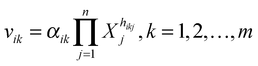 , where the rate constant αik and the kinetic orders hikj are fundamental characteristics. The rate constant describes the turn-over of the process, while the kinetic orders quantify the strengths with which reactants and regulators affect the process. These parameters need to be estimated to provide a full description of the metabolic pathway under study.
3.4. Details of the mathematical representation of the L. lactis model
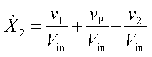
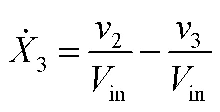
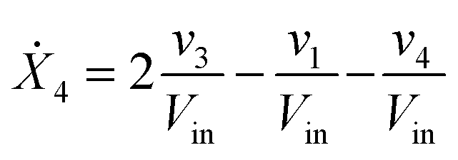
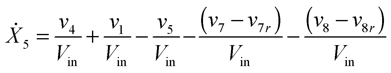
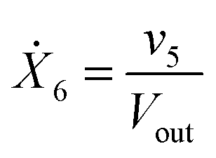
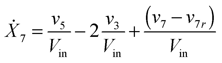
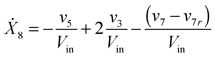
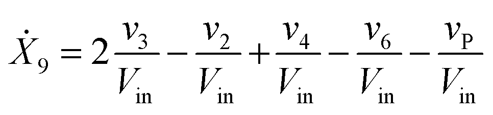
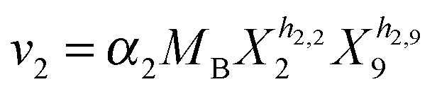
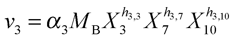
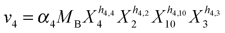
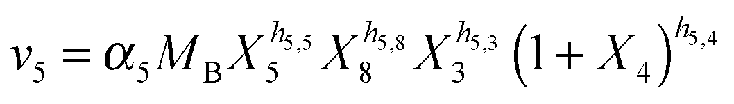
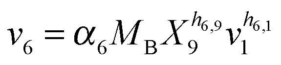
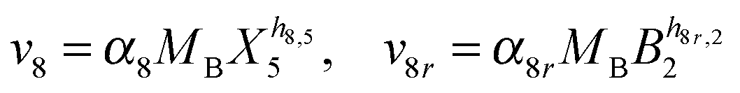
Our default for the functional forms of fluxes in the L. lactis model is a product of power-law functions, so that the model is mostly in the generalized mass action (GMA) format within the framework of BST. However, we allow for deviations from this format if they are suggested by the DFE analysis. The result is presented in eqn (1) and (2). In addition to the typical BST parameters, namely rate constants and kinetic orders, the equations contain the intracellular and extracellular volumes Vin and Vout. The extracellular volume of the bioreactor is 50 ml in all three experiments, while the intracellular volume is calculated from the measured biomass concentration, MB, in each case, using a conversion value of 2.9 μL mg−1 of protein for the intracellular volume.39 Thus, Vin = 0.0029 VoutMB. The differential equations need to account for these volume differences, because the amounts of biomass differ among the experiments. B1 and B2 in eqn (2h) and (2i) are temporary buffers.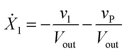 | (1a) |
 | (1b) |
 | (1c) |
 | (1d) |
 | (1e) |
 | (1f) |
 | (1g) |
 | (1h) |
 | (1i) |
 | (1j) |
 | (1k) |
 | (1l) |
 | (2a) |
 | (2b) |
 | (2c) |
 | (2d) |
 | (2e) |
 | (2f) |
 | (2g) |
 | (2h) |
 | (2i) |
 and (1 + X4)−h1,4 in eqn (2a).
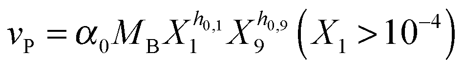
Several options are available to address the initial brief rise in PTS. First, one could attempt to identify the true mechanisms leading to the initial increase in glucose uptake, which corresponds to the sigmoidal shape of the glucose concentration curve. For instance, one could explain this observation with the fact that the experimental set-up causes slight delays, which could affect the uptake profile. It has also been argued9 that the cells might recover from starvation with some variability, which could be due to cell-to-cell variation in the speed of glucose uptake or slight differences in glucose availability to individual cells, or could be caused by the process of mixing of glucose throughout the medium or other extraneous factors. Indeed, it was shown with simulations that a narrowly distributed uptake profile can directly convert the monotonic trend in glucose consumption, as predicted by the model structure, into a sigmoidal trend, as it is observed.9 As an alternative, one could try to identify some fitting function without being constrained by mechanistic considerations.41 One could furthermore use the data directly as (“off-line”) inputs instead of representing them functionally in the model.42 Finally, one could imagine that insufficient amounts of FBP accumulate during the first two minutes, thereby limiting the material flux into the pool of PEP and 3PGA. As a consequence, the initial PEP concentration might not be able to produce the high level of v1 that we directly computed through numerical differentiation of the glucose consumption profile. This short-term discrepancy can be resolved when we account for a small auxiliary permease flux (vP), which has been observed in this strain of L. lactis,43 but was never used in earlier models.
Given the variety of speculations, we decided on a hybrid option, where we use a black-box adjustment function for the first two minutes and dynamically model glucose uptake afterwards, starting at t = 2 [min]. Specifically, we multiply a term of the form 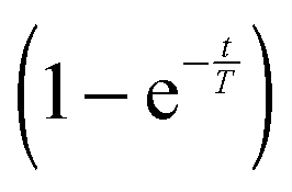 to the modeled PTS flux. This term, which is borrowed from physics and engineering,44 where it typically represents a delayed response of a linear time-invariant system to a constant input starting at time zero, does not convey biological meaning. It is simply useful since it exponentially approaches 1 and loses its effect after a short period of time. For instance, at 3T minutes, it is equal to 1 − e−3 = 0.9502. Thus, the term is ineffective for most of the experimental period. Different time constants T were allowed for different experiments.
3.5. Summary of the model design procedure
In broad strokes, the modeling strategy employed here consisted of the following main steps: (1) initially, the first phase of DFE was used, which resulted in the identification of a subset of fluxes. However, because the stoichiometric matrix is not full rank and some of the measurements were missing, some fluxes could not be identified in this step. (2) For the identifiable subset of fluxes, diagnostic methods were utilized in the second phase of DFE to ensure the validity of power-law representation as well as the reasonableness of each of the hypothesized underlying regulatory mechanisms. This step provided starting points for parameters that were used in the later optimization algorithms. (3) Loose boundaries on parameter values were imposed and additional constraints were taken into account including those resulting from the detailed analysis of the FBP dynamics (see Section 4.2). (4) The information from steps 2 and 3 was used as input to a suite of several global and local optimization algorithms, which ultimately led to one parameter set that minimizes the error between the experimental measurements and the simulation results. Finally, Monte-Carlo methods and randomization schemes were utilized to search the parameter space as thoroughly as possible to ensure the optimality of the parameter set and to characterize a compact ensemble of close-by, good solutions. While these strategies reduced the chance of other, distinctly different solutions, they do not provide a mathematical proof.4 Results
4.1. General features of the model
Based on literature information, we established an initial model diagram (Fig. 2), determined fluxes with methods of DFE, and subsequently performed parameter estimation. The fully parameterized model was diagnosed with standard methods of stability, sensitivity, and robustness analysis, and subsequently used for representative simulations.The analysis led to several slight amendments of the original diagram. First, we observed that the actually measured total carbon mass decreases over time for all three datasets, with about 7–10% of the mass being unaccounted (see Fig. 6A in a later section), in spite of the fact that, outside glycolysis, the organism is metabolically inactive under the given conditions.10 The loss is biologically not very significant, but it is immediately inconsistent with the model structure of the initial diagram, where glucose is the only input substrate and lactate is the only output. The most reasonable option for remedying this inconsistency is the addition of a minor efflux out of one or more metabolite pools. A good candidate is pyruvate, because several reactions may use pyruvate as a substrate and thereby be responsible for the diversion of material.45 Because some of these effluxes potentially affect the NAD+/NADH balance, we included two types of leakage from pyruvate, one with and one without the consumption of NADH. Optimization determined the very low capacities of these fluxes. We also considered alternative locations of leakage, such as PEP and G6P, but did not find them beneficial under the given experimental conditions. Other amendments are discussed in the following sections.
The model contains twelve dependent variables. Six represent the main metabolites glucose, G6P, FBP, the aggregated pool of 3PGA and PEP, pyruvate, and lactate, four variables represent the cofactors ATP, ADP, NAD+, and NADH, and the remaining two represent temporary buffers.46 The buffers were used for the following reason. When we studied both carbon flow and electron flow, we observed a temporal mismatch that required some NADH to be consumed but later returned to the pathway. We rationalized this observation with the possibility that one or more pools must exist in connection with some glycolytic intermediates that allow NADH to be consumed and later returned. These reactions could include processes such as the mannitol-1P dehydrogenase or glycerol-3P dehydrogenase steps. The fact that there are several possible pools might explain why no other metabolite was actually measured by the NMR, because if the missing mass is distributed among several pools, none would have a concentration high enough to be detectable by the NMR. We therefore allowed for two buffers to exist in the model, one out of G6P and one out of pyruvate. No parameter set was ever obtained, by optimization, which used the buffer out of G6P, which suggested removal of this buffer. The best data consistency was always obtained with the two buffers presented, one NADH dependent and one NADH independent. These allowed the model to accommodate the carbon-electron temporal mismatch.
Eqn (1) of the previous section presents ordinary differential equations describing the system connectivity, while eqn (2) shows the functional representations. The model is more complicated than earlier models of glycolysis in L. lactis, as it addresses the pathway dynamics under anaerobic conditions. In contrast to aerobic conditions, the organism cannot easily recycle NAD+ under anaerobic conditions, and the balance between NAD+ and NADH therefore changes dynamically. These changes must be expected to affect the dynamics of glycolysis and are therefore considered important for the model.
4.2. Temporarily steady FBP peak
An intriguing observation among the three experiments is that FBP reaches more or less the same peak level as long as a certain minimal level of glucose is available to the system (Fig. 1). This observation has been puzzling for a long time but can now be explained with a detailed analysis of the model structure and the quantitative features of its fluxes. The mathematical and biological details of the explanation are discussed below. In a nutshell, the shapes of the peaks are driven by saturation of the PTS flux (v1), while the subsequent production flux of FBP (v3) operates below saturation and while the FBP concentration results in a v3 flux equal to the saturated PTS flux v1. The proposed relationship between v1 and v3 yields strong mathematical constraints that restrict the admissible parameter space. In particular, the analysis reveals that glucose must have a low kinetic order in the PTS flux. Interestingly, similar considerations of relationships among kinetic Michaelis–Menten parameters have recently helped explain ultra-sensitivity in cascaded signaling systems.47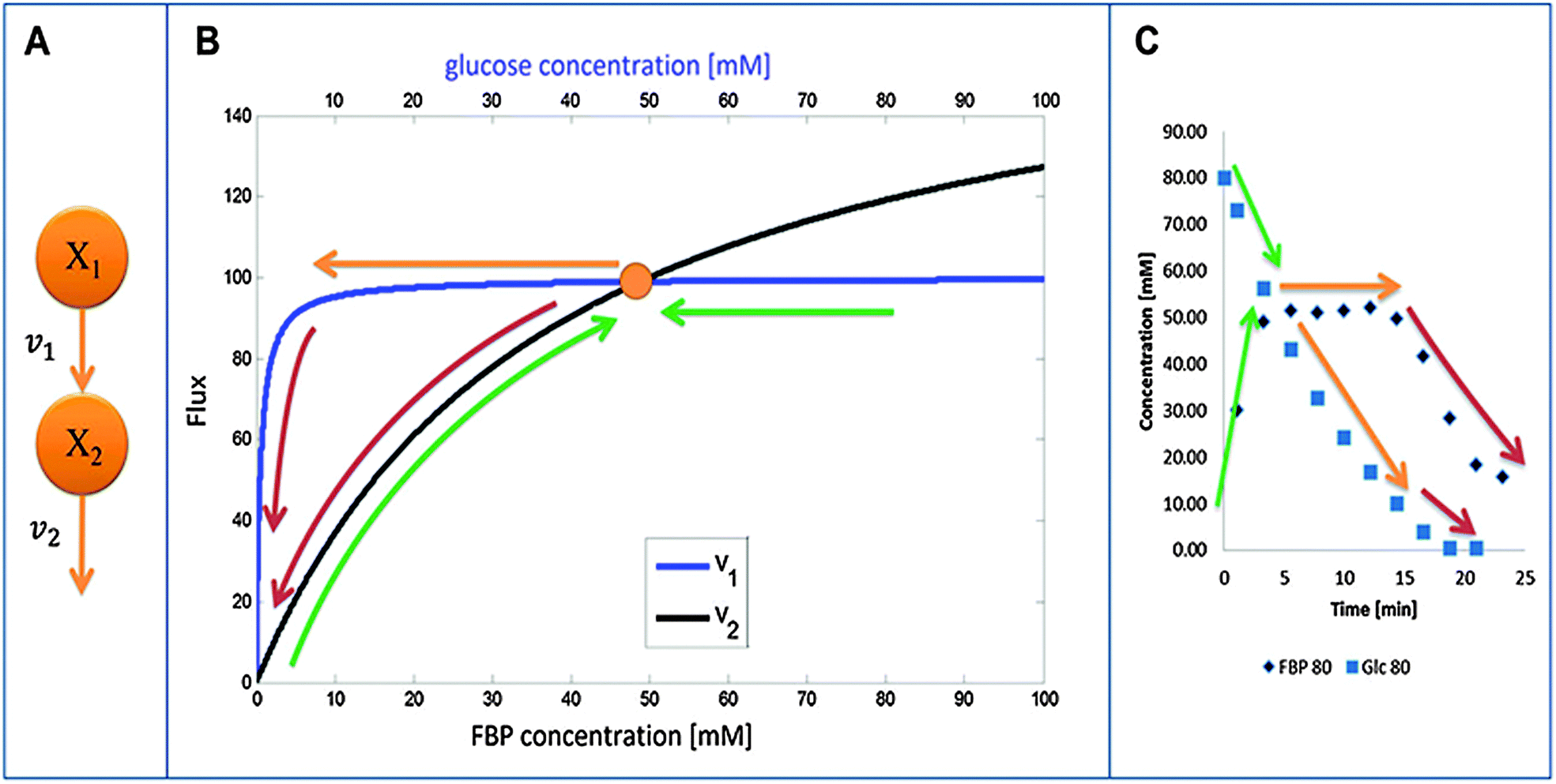 | ||
| Fig. 3 (A) Simplified diagram of glucose (X1) conversion into FBP (X2). Panel (B) depicts the relative shapes of v1 and v2 as functions of their substrate concentrations. Colored arrows show different phases of the dynamic behavior of FBP. Green: FBP accumulation and decrease in glucose (first 5 minutes); orange: FBP constancy at peak level and further decrease in glucose (∼15 minutes for 80 mM glucose); red: glucose and FBP depletion. Panel (C) shows the same phases on a concentration vs. time plot. The color coding is consistent between (B and C). | ||
Fig. 3B visualizes the dynamics of fluxes of accumulation (v1) and consumption (v2) of FBP relative to one another for the representative case of Experiment 3 with 80 mM of initial glucose. The horizontal top and bottom axes for the two curves are different and color-coded with blue (glucose) and black (FBP). In the first phase of the experiment, glucose is abundant and FBP accumulates (shown with a curved green upward arrow) while glucose is being consumed at a more or less constant rate (shown with the horizontal green arrow indicating that glucose is consumed at the same time as FBP accumulates). The intersection of the curves represents a temporarily steady state for FBP with a concentration of about 50 mM. At this state, accumulation and consumption of FBP are in balance: v1 = v2, while other processes in the system are not. As the experiment proceeds, FBP remains constant, whereas glucose is being consumed from about 50 mM down to about 10 mM (color-coded with straight orange arrow). Since the value of v1 is essentially constant, FBP remains at its temporary plateau during this period. As soon as the glucose concentration drops below about 10 mM, FBP becomes depleted while glucose is being used up as the two red arrows indicate. Panel (C) shows the same three phases on a concentration vs. time plot of glucose and FBP for further clarification.
The concepts outlined above were implemented in a simple model. We start by representing the flux terms with Michaelis–Menten rate laws. In order to obtain the same peak for different amounts of glucose, v1 needs to be saturated and equal to Vmax1 for glucose with a value between about 10 to 80 mM for Experiment 1 and between about 5 to 40 mM for Experiment 2. These numerical settings permit the temporarily steady state and extended peak for FBP if v2 has a high Vmax2 and a low Km2. In fact, these values must be such that for the peak FBP concentration (about 50 mM), v2 equals v1 for the appropriate glucose concentrations.
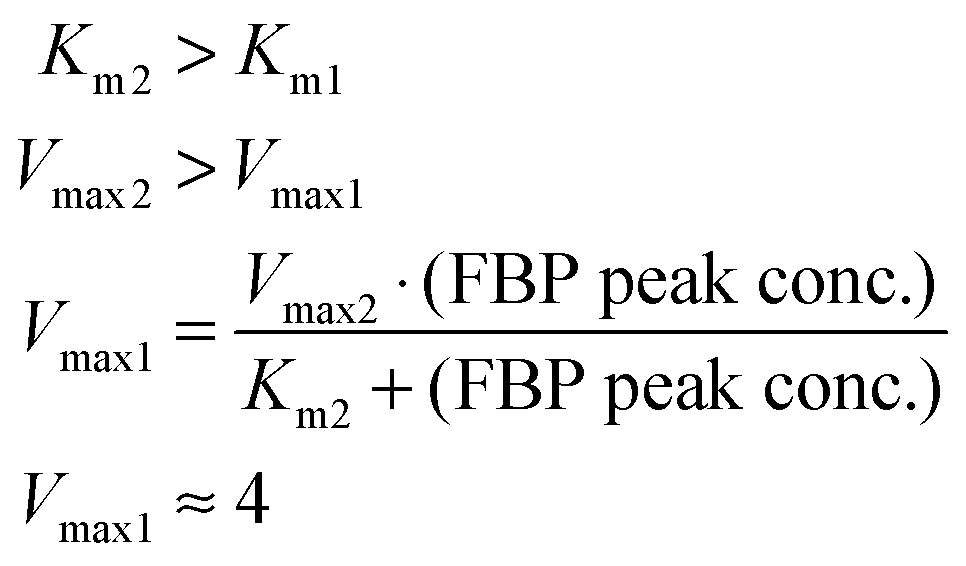
These quantitative considerations can be converted into constraints for the model parameters. Specifically, the equation v2(FBP = 50) = v1(5 ≤ glucose ≤ 50) mandates the following: First, Km1 must be such that v1 is saturated for high glucose values (above about 5 mM); this ensures a similar FBP peak for all pertinent glucose concentrations in the three experiments. Second, the FBP accumulation and consumption fluxes v1 and v2 need to intersect. This requires Km2 > Km1 and Vmax2 > Vmax1, and the values must be set such that v1 = v2 when FBP is at the observed plateau of about 50 mM. A solution to these constraints is:
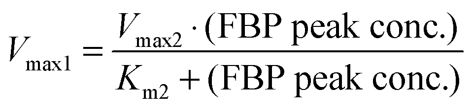
Fig. 4A shows the glucose and FBP dynamics resulting from a representative example for which the inferred sets of constraints hold. The concentration curves are very similar to the measurement data (Fig. 1).
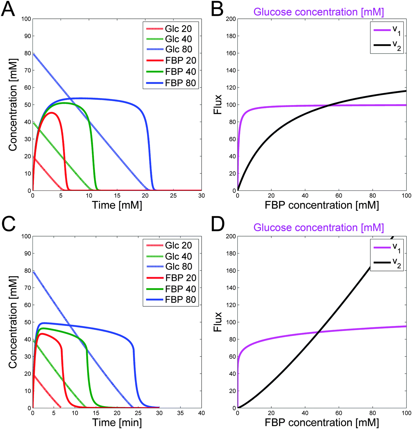 | ||
| Fig. 4 (A) Computed concentrations of glucose (more or less linear) and FBP (humped) for 20 (red), 40 (green), and 80 mM (blue) of initial glucose, using the constraints on parameters in a Michaelis–Menten formulation with representative values of Vmax1 = 4, Vmax2 = 145, Km1 = 0.5, Km2 = 25 and an external to internal volume ratio of 25. (B) Corresponding glucose and FBP trends vs. time for the Michaelis–Menten formulation in (A). (C) Plots of flux vs. concentration for the v1 and v2 fluxes in power-law format. v1 has a low kinetic order. (D) Corresponding glucose and FBP trends vs. time for the power-law formula in (C). Experiment 3 with the highest amount of glucose input results in the most extended FBP peak. | ||
The relationships between fluxes are not dependent on the choice of the Michaelis–Menten framework. To reproduce similar conditions for power-law representations, one must simply require a low kinetic order and rate constant for glucose that results in the correct dynamics for v1. The result is a similar flux value for different glucose concentrations between 5 and 50 mM. Furthermore, v2 needs to have a higher kinetic order so that the two flux curves intersect. Rate constants are calculated such that v1 = v2 for the peak FBP concentration of about 50 mM. Similar to the Michaelis–Menten case, the kinetic order and rate constant for v1 need to be set such that they satisfy the speed for glucose depletion. Results for a representative, feasible parameter set with power-law functions are illustrated with the fluxes in Fig. 4C. Fig. 4D shows the corresponding glucose and FBP concentrations for the three experiments with different initial glucose concentrations.
The question arises of whether the above considerations are affected by the existence of G6P as an intermediate between glucose and FBP. The short answer is no. Unfortunately, the [1-13C] NMR experiments did not permit measurements of G6P for the three experiments. However, it is likely that the G6P dynamics is similar to the FBP dynamics, although with a lower peak value or a very low saturation threshold as it is observed for Experiment 1 with initial glucose of 20 mM.
Supposing that v3 is a function of FBP only, we find: (i) at times when FBP is constant, v3 is constant as well; and (ii) FBP being constant requires that v2 = v3. (i) and (ii) are possible in the following two scenarios only when G6P and FBP are constant simultaneously, or when v2 is saturated for the amount of G6P during that time period, and therefore has a very low Km. Furthermore, no matter whether G6P is constant or v2 has a low Km (high affinity) for G6P, v1 = v2 = v3 must hold at the FBP peak, and v1 must thus be saturated for glucose values between about 5 and 50 mM as reasoned before. Thus, the earlier conclusions regarding the FBP dynamics hold, whether or not G6P is explicitly presented.
4.3. Fully parameterized model and model fits
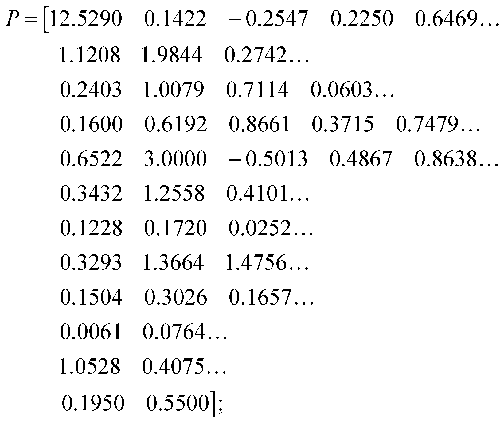
Methods of DFE, combined with numerous parameter estimation techniques, led to the following set of parameter values, which lead to simultaneous fits for the three available experiments. They are displayed below with one row per flux: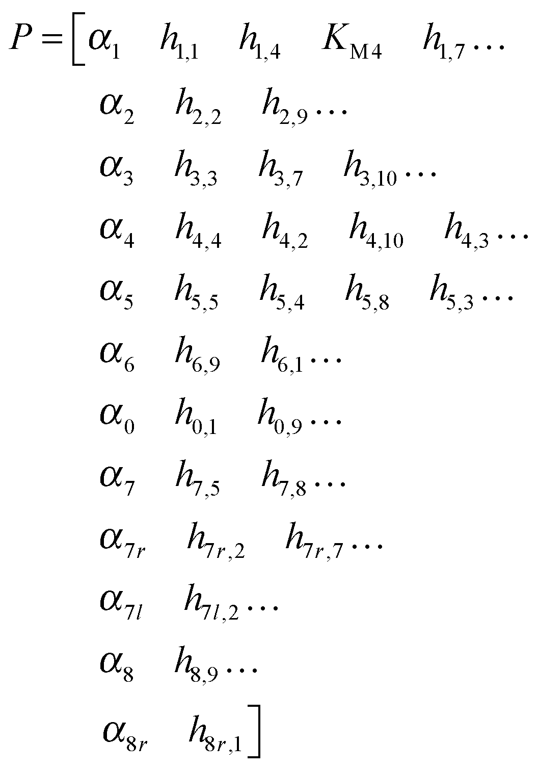 | (3) |
 | (4) |
| X080 = [80; 0.1; 4; 14.8; 0.1; 0.1; 5.74; 0.1; 0.1; 8.815; 0.1; 0.1]; |
| X040 = [40; 0.1; 4; 14.8; 0.1; 0.1; 5.74; 0.1; 0.1; 8.815; 0.1; 0.1]; |
| X020 = [20; 0.1; 4; 14.8; 0.1; 0.1; 5.74; 0.1; 0.1; 8.815; 0.1; 0.1]; |
| MB−20 = 13.92 mg protein per ml |
| MB−40 = 17.11 mg protein per ml |
| MB−80 = 19.53 mg protein per ml |
| T20 = 0.7124 min |
| T40 = 0.7450 min |
| T80 = 1.6661 min |
These parameter settings lead to good fits of the data, which are displayed in panels (A–C) of Fig. 5. The capacity of a single parameter set to capture different conditions is important, because it significantly increases the predictive power of the model. Furthermore, since this parameter set was derived from DFE, its extrapolation reliability is increased, because the risk of error compensation among flux terms within the same or in different equations is greatly reduced.7
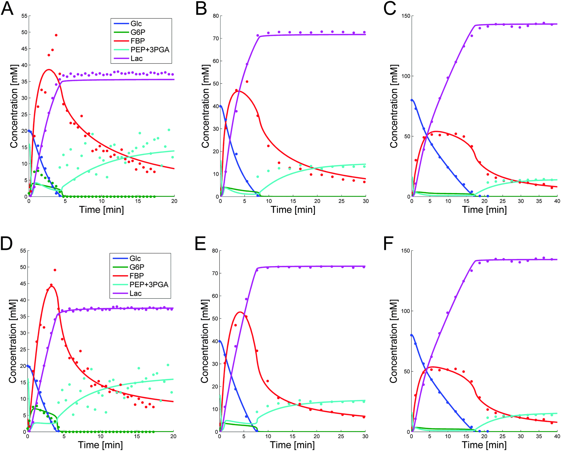 | ||
| Fig. 5 Simulation results for glucose, lactate, G6P, FBP and PEP + 3PGA, superimposed on the corresponding data, for Experiment 1 (panel A), Experiment 2 (panel B), and Experiment 3 (panel C). Note the different Y-scales. Accounting for modest variability among cell populations, the parameters in the common set of panels (A–C) were allowed to vary slightly among experiments. The resulting fits are depicted in panels (D–F). | ||
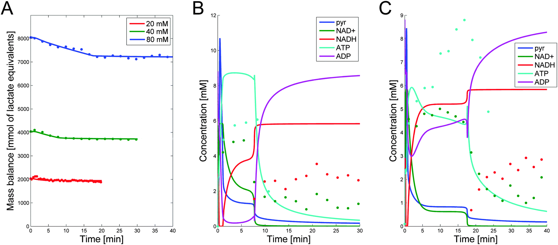 | ||
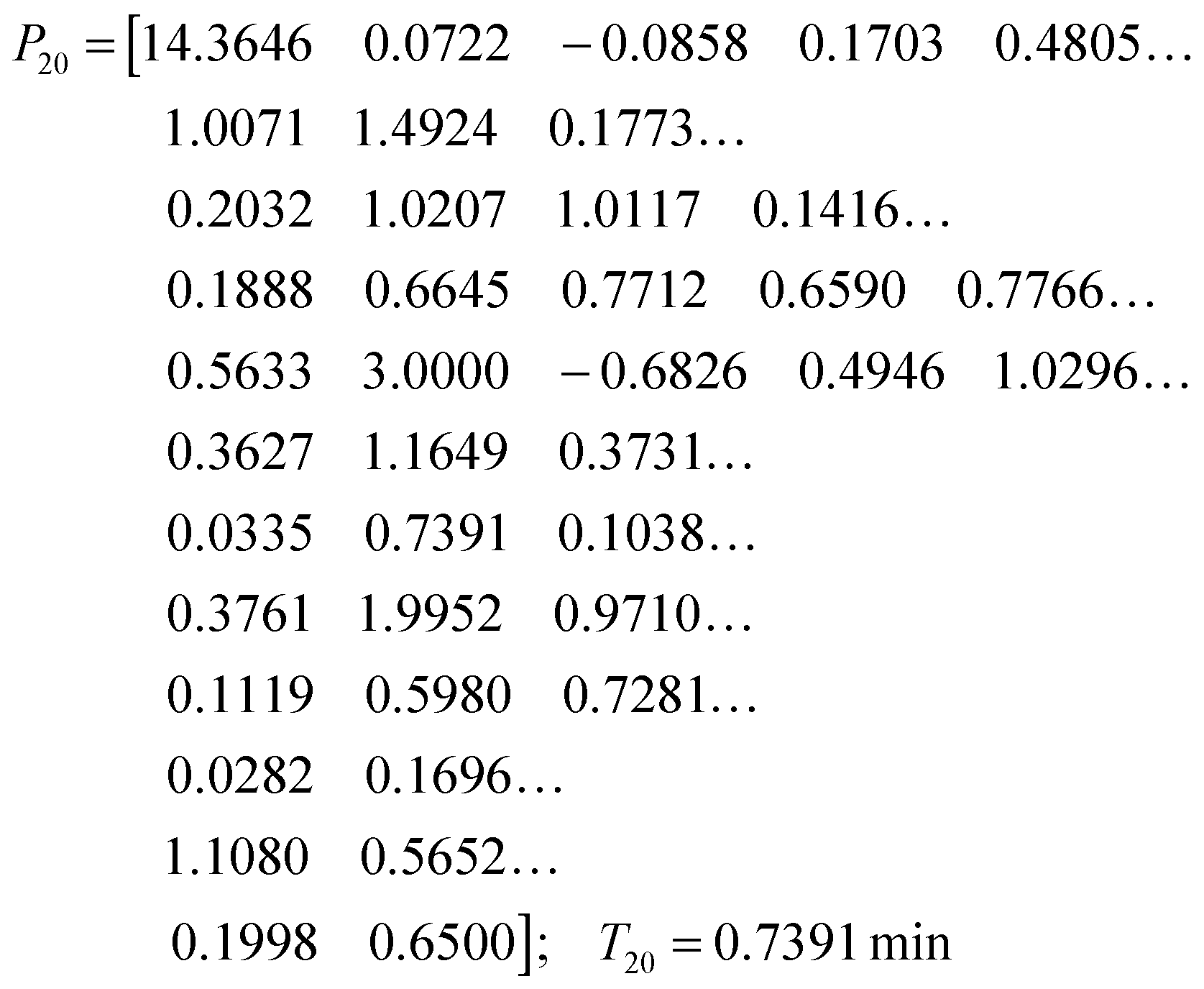
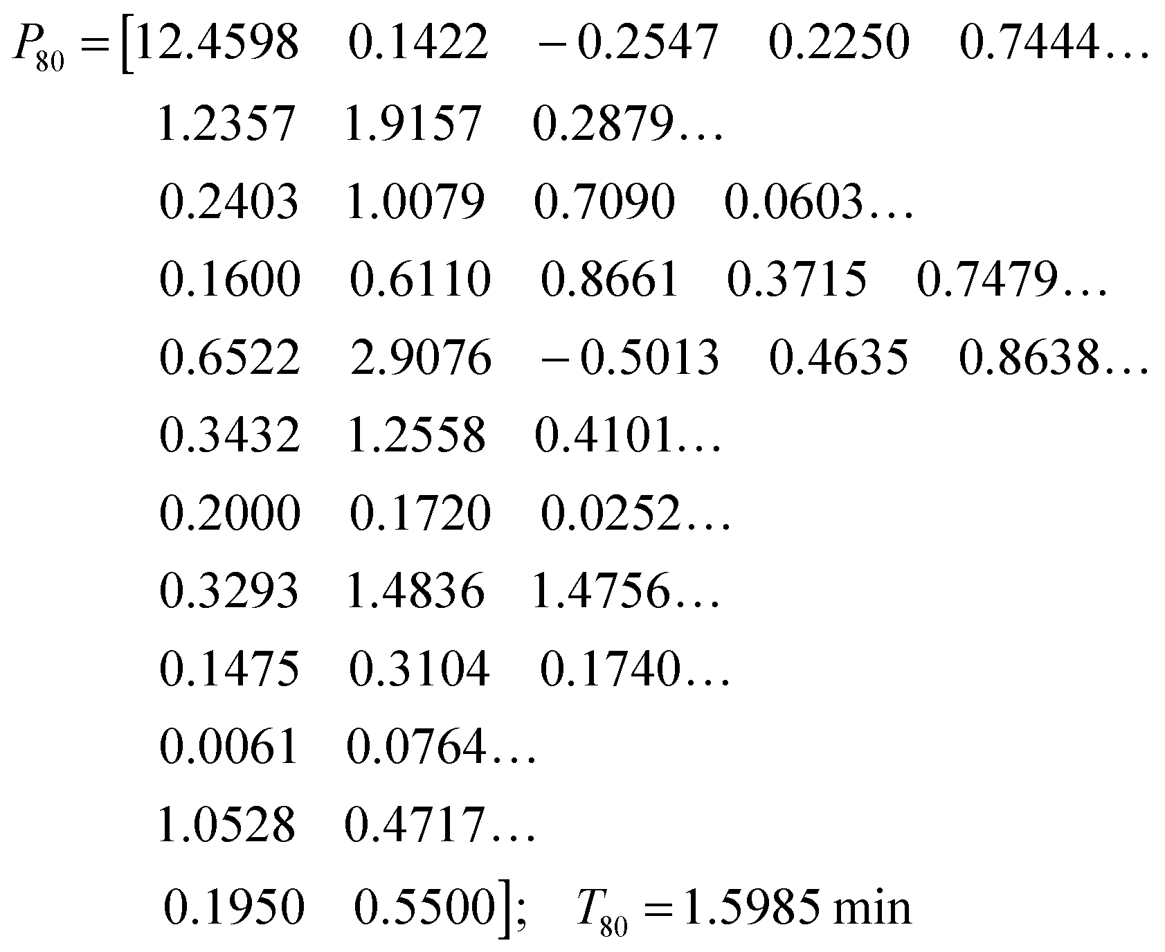
| Fig. 6 (A) Mass balance in mmol of lactate equivalents vs. time, calculated by taking into account the appropriate stoichiometry and volume conversions. The mass is plotted for the three datasets. The dots show the total carbon mass calculated from the measured data, and the lines show the calculated amounts resulting from the simulated model with leakage terms. (B,C) Data of NAD+, NADH and ATP are shown as dots. Simulation results for NAD+, NADH and ATP are superimposed. No data are available for pyruvate; simulation results are shown in dark blue. Panels B and C show the data and simulation results for Experiment 2 (40 mM glucose) and Experiment 3 (80 mM of glucose), respectively. | ||
While the simultaneous fitting with one parameter set is important, one should consider that, in reality, natural systems obviously exhibit a certain degree of variability. We therefore allowed the parameters in the common set, which fits the three experiments simultaneously, to vary slightly in order to account for this variability among the different cell populations. The results are shown in panels (D–F) of Fig. 5. These model instantiations used the following parameter sets for the 20, 40, and 80 mM experiment. A parameter-by-parameter comparison demonstrates how close the three sets are.
 | (5) |
 | (6) |
 | (7) |
4.4. Simulation results for secondary metabolites
NAD+, NADH, and ATP data are available only for Experiments 2 and 3. The simulation results for these metabolites as well as pyruvate are shown in Fig. 6B and C. Although the fits are not as good as those for the main metabolites, they capture the trends and timing. Three aspects are of note. First, these secondary metabolites all have concentrations below 10 mM and are often close to the detection limit. Second, the ATP measurements had to be performed in a separate experiment, as phosphate was labeled, and while an attempt was made to match the experimental conditions as closely as possible to the 40 and 80 mM experiments, the data did not come from the same experiments. Finally, NADH was not observed until the time point when glucose was depleted in these experiments. With these limitations in mind, emphasis with respect to ATP was given to the general trend of an increase to high concentrations in the beginning of the experiment, remaining high for the duration of experiment until glucose was depleted, then being depleted. For NADH, it was important to remain at its high concentration for the duration of time after the glucose depletion. Furthermore, no pyruvate was detected in the experiments. Consistently, the simulation results are below the detection limit of each experiment, except for the first few minutes where unlabeled PEP and 3PGA are converted into unlabeled pyruvate that remains undetected in NMR experiments. The simulation results show this spike in the beginning; shortly afterwards, pyruvate decreases to below 2 mM for all experiments and stays below the detection limit until it approaches zero toward the end of the experiment.5 Conclusions and future directions
A dynamic mathematical model was devised that accounts for the key glycolytic metabolites in L. lactis, as well as the dynamics of such cofactors as NAD+, NADH, ATP, and ADP. As with many modeling studies, the most difficult step of model development was the estimation of parameter values. Here, this estimation was based on experimental time series of glycolytic intermediates from three experiments with different substrate availability. The technical difficulties of the estimation process were directly related to the high dimensionality of the parameter space, the enormous complexity of the landscape of residual errors between model and data, and the often ignored fact that we do not really know what functions are best suited to represent each process within a biological system. To address these issues, a combination of mathematical and computational techniques were developed, including a custom-tailored Monte-Carlo algorithm, various optimization techniques and, most importantly, methods of dynamic flux estimation (DFE), which enabled us to reduce the admissible parameter space and prevent flux terms from compensating errors in their representations.For the first time, a single model fits all available metabolic time courses reasonably well with the same parameter set and also captures the counterintuitive FBP dynamics across the three experiments. Because this model reflects three independent datasets, one might expect that it has a higher extrapolation potential than earlier models that were based on single datasets. The companion paper1 discusses key aspects of the control of the pathway, and explains in detail how the organism terminates glycolysis at the end of glucose availability such that it is ready to take up now glucose as soon as substrate becomes available again.
Acknowledgements
The authors are grateful to Dr Helena Santos and Dr Ana Rute Neves of the Instituto de Tecnologia Química e Biológica (ITQB) at the New University of Lisbon (Portugal) for allowing them to use the in vivo NMR data presented here. The NMR spectrometers are part of The National NMR Facility (RECI/BBB-BQB/0230/2012), supported by Fundação para a Ciência e a Tecnologia. This work was funded in part by the National Science Foundation (Projects MCB-0958172 and MCB-0946595; PI: EOV). The funding agency is not responsible for the content of this article.References
- S. Dolatshahi, L. L. Fonseca and E. O. Voit, Mol. BioSyst., 2015 10.1039/c5mb00726g.
- A. El-Aneed, A. Cohen and J. Banoub, Appl. Spectrosc. Rev., 2009, 44, 210–230 CrossRef CAS.
- S. Li, Y. Park, S. Duraisingham, F. H. Strobel, N. Khan, Q. A. Soltow, D. P. Jones and B. Pulendran, PLoS Comput. Biol., 2013, 9, e1003123 CrossRef CAS PubMed.
- A. R. Neves, W. A. Pool, J. Kok, O. P. Kuipers and H. Santos, FEMS Microbiol. Rev., 2005, 29, 531–554 CAS.
- R. V. Bruggner, B. Bodenmiller, D. L. Dill, R. J. Tibshirani and G. P. Nolan, Proc. Natl. Acad. Sci. U. S. A., 2014, 111, E2770–E2777 CrossRef CAS PubMed.
- I.-C. Chou and E. O. Voit, Math. Biosci., 2009, 219, 57–83 CrossRef CAS PubMed.
- G. Goel, I. C. Chou and E. O. Voit, Bioinformatics, 2008, 24, 2505–2511 CrossRef CAS PubMed.
- M. H. Hoefnagel, A. van der Burgt, D. E. Martens, J. Hugenholtz and J. L. Snoep, Mol. Biol. Rep., 2002, 29, 157–161 CrossRef CAS PubMed.
- E. O. Voit, J. Almeida, S. Marino, R. Lall, G. Goel, A. R. Neves and H. Santos, Syst. Biol., 2006, 153, 286–298 CrossRef CAS.
- A. R. Neves, A. Ramos, M. C. Nunes, M. Kleerebezem, J. Hugenholtz, W. M. de Vos, J. Almeida and H. Santos, Biotechnol. Bioeng., 1999, 64, 200–212 CrossRef CAS PubMed.
- A. R. Neves, PhD dissertation, Universidade Nova de Lisboa, 2001.
- A. R. Neves, A. Ramos, H. Costa, S. van, II, J. Hugenholtz, M. Kleerebezem, W. de Vos and H. Santos, Appl. Environ. Microbiol., 2002, 68, 6332–6342 CrossRef CAS PubMed.
- A. R. Neves, R. Ventura, N. Mansour, C. Shearman, M. J. Gasson, C. Maycock, A. Ramos and H. Santos, J. Biol. Chem., 2002, 277, 28088–28098 CrossRef CAS PubMed.
- J. B. Clarke, M. Birch and H. G. Britton, Biochem. J., 1974, 139, 491–497 CrossRef CAS PubMed.
- B. G. Malmstrom, The Enzymes, ed. P. D. Boyer, H. Lardy and K. Myrbäck, Academic Press, New York and London, 2nd edn, 1961, ch. 471, vol. V Search PubMed.
- F. Marcel and S. Elmer, Comprehensive Biochemistry, Elsevier, 1969, vol. 17, p. 136 Search PubMed.
- M. Kanehisa, S. Goto, Y. Sato, M. Kawashima, M. Furumichi and M. Tanabe, Nucleic Acids Res., 2014, 42, D199–D205 CrossRef CAS PubMed.
- R. Caspi, T. Altman, R. Billington, K. Dreher, H. Foerster, C. A. Fulcher, T. A. Holland, I. M. Keseler, A. Kothari, A. Kubo, M. Krummenacker, M. Latendresse, L. A. Mueller, Q. Ong, S. Paley, P. Subhraveti, D. S. Weaver, D. Weerasinghe, P. Zhang and P. D. Karp, Nucleic Acids Res., 2014, 42, D459–D471 CrossRef CAS PubMed.
- P. Gennemark and D. A. G. Wedelin, J. Bioinf. Comput. Biol., 2013, 12, 1350015 CrossRef PubMed.
- E. O. Voit, in Applied Statistics for Biological Networks, ed. M. Dehmer, F. Emmert-Streib and A. Salvador, J. Wiley and Sons, New York, 2011, pp. 183–200 Search PubMed.
- I. C. Chou and E. O. Voit, BMC Syst. Biol., 2012, 6, 84 CrossRef PubMed.
- M. Iwata, F. Shiraishi and E. O. Voit, Int. J. Syst. Biol., 2013, 4, 57–72 Search PubMed.
- E. O. Voit, Math. Biosci., 2013, 246, 315–325 CrossRef CAS PubMed.
- E. O. Voit, G. Goel, I.-C. Chou and L. da Fonseca, IEE Proc.: Syst. Biol., 2009, 3, 513–522 CAS.
- M. Vilela, C. C. Borges, S. Vinga, A. T. Vasconcelos, H. Santos, E. O. Voit and J. S. Almeida, BMC Bioinf., 2007, 8, 305 CrossRef PubMed.
- S. Dolatshahi, B. Vidakovic and E. O. Voit, Comput. Chem. Eng., 2014, 71, 728–733 CrossRef CAS.
- E. O. Voit and J. Almeida, Bioinformatics, 2004, 20, 1670–1681 CrossRef CAS PubMed.
- R. N. Gutenkunst, F. P. Casey, J. J. Waterfall, C. R. Myers and J. P. Sethna, Ann. N. Y. Acad. Sci., 2007, 1115, 203–211 CrossRef PubMed.
- R. N. Gutenkunst, J. J. Waterfall, F. P. Casey, K. S. Brown, C. R. Myers and J. P. Sethna, PLoS Comput. Biol., 2007, 3, 1871–1878 CrossRef CAS PubMed.
- S. Srinath and R. Gunawan, J. Biotechnol., 2010, 149, 132–140 CrossRef CAS PubMed.
- M. Vilela, S. Vinga, M. A. Maia, E. O. Voit and J. S. Almeida, BMC Syst. Biol., 2009, 3, 47 CrossRef PubMed.
- P. J. Sands and E. O. Voit, Ecol. Modell., 1996, 93, 75–88 CrossRef.
- E. O. Voit, ISRN Biomath., 2013, 2013, 53 Search PubMed.
- M. A. Savageau, Biochemical Systems Analysis: A Study of Function and Design in Molecular Biology, Addison-Wesley Pub. Co., Advanced Book Program (reprinted 2009), Reading, Mass, 1976 Search PubMed.
- E. O. Voit, Computational analysis of biochemical systems: a practical guide for biochemists and molecular biologists, Cambridge University Press, Cambridge, New York, 2000 Search PubMed.
- M. A. Savageau, J. Theor. Biol., 1969, 25, 365–369 CrossRef CAS PubMed.
- Canonical Nonlinear Modeling. S-System Approach to Understanding Complexity, ed. E. O. Voit, Van Nostrand Reinhold, NY, 1991 Search PubMed.
- M. A. Savageau and E. O. Voit, Math. Biosci., 1987, 87, 83–115 CrossRef.
- B. Poolman, K. J. Hellingwerf and W. N. Konings, J. Bacteriol., 1987, 169, 2272–2276 CrossRef CAS PubMed.
- J. L. Galazzo and J. E. Bailey, Enzyme Microb. Technol., 1990, 12, 162–172 CrossRef CAS.
- A. Hartmann, J. M. Lemos and S. Vinga, Comput. Biol. Med., 2015, 63, 301–309 CrossRef CAS PubMed.
- S. Marino and E. O. Voit, J. Bioinf. Comput. Biol., 2006, 4, 665–691 CrossRef CAS.
- R. Castro, A. R. Neves, L. L. Fonseca, W. A. Pool, J. Kok, O. P. Kuipers and H. Santos, Mol. Microbiol., 2009, 71, 795–806 CrossRef CAS PubMed.
- B. G. Lipták, Instrument Engineers' Handbook- Process Control and Optimization, Taylor & Francis, 4th edn, 2006 Search PubMed.
- P. Gaspar, A. L. Carvalho, S. Vinga, H. Santos and A. R. Neves, Biotechnol. Adv., 2013, 31, 764–788 CrossRef CAS PubMed.
- E. O. Voit and A. E. N. Ferreira, J. Theor. Biol., 1998, 191, 429–438 CrossRef CAS.
- J. E. J. Ferrell and S. H. Ha, Trends Biochem. Sci., 2014, 39, 496–503 CrossRef CAS PubMed.
| This journal is © The Royal Society of Chemistry 2016 |