
 Open Access Article
 This Open Access Article is licensed under a Creative Commons Attribution-Non Commercial 3.0 Unported Licence
Assessment of colorimetric amplification methods in a paper-based immunoassay for diagnosis of malaria†
Shefali
Lathwal
and
Hadley D.
Sikes
*
Department of Chemical Engineering, Massachusetts Institute of Technology, 77 Massachusetts Avenue, Cambridge, MA 02139, USA. E-mail: sikes@mit.edu
First published on 9th March 2016
Abstract
Colorimetric detection methods that produce results readable by eye are important for diagnostic tests in resource-limited settings. In this work, we have compared three main types of colorimetric methods – enzymatic reactions, silver deposition catalyzed by gold nanoparticles, and polymerization-based amplification – in a paper-based immunoassay for detection of Plasmodium falciparum histidine-rich protein 2, a biomarker of malarial infection. We kept the binding events in the immunoassay constant in order to isolate the effect of the detection method on the outcome of the test. We have highlighted that the optimal readout time in a test can vary significantly – ranging from immediately after addition of a visualization agent to 25 minutes after addition of a visualization agent – depending on the colorimetric method being used, and accurate time keeping is essential to prevent false positives in methods where substantial color develops over time in negative tests. We have also shown that the choice of a colorimetric method impacts the calculated limit-of-detection, the ease of visual perception of the readout, and the total cost of the assay, and therefore directly impacts the feasibility and the ease-of-use of a test in field settings.
1. Introduction
Detection methods that produce a visible change in color in the presence of an analyte are widely used in point-of-care (POC) assays.1,2 These colorimetric methods provide an equipment-free readout using the unaided eye, which is useful in resource-limited settings (RLS) without laboratory infrastructure.3 In recent years, cellulose-based materials such as chromatography paper and filter paper have emerged as an attractive platform for developing colorimetric tests for RLS1,4,5 because of their low cost and ease of fabrication.1,6 Such paper-based tests have been developed for many applications including diagnostics.1Currently, the most widely used colorimetric diagnostic tests in RLS are lateral flow immunoassays.2,7 These tests are commercially available for a variety of analytes, but unreliable appearance of color is a commonly reported problem8,9 that decreases confidence in these tests. In paper-based immunoassays, colorimetric methods based on enzymatic amplification10–12 and gold nanoparticles with11 and without13 silver deposition have been reported. The results for these tests are recorded within a specific time interval since the color produced is dependent on time. This time-dependence is often overlooked during development since accurate time-keeping is not a concern in laboratory settings. However, accurate time-keeping is an undesirable requirement in field settings5 and can become a hurdle when only a few health care workers are available to tend to the needs of many patients. We recently reported the development of a colorimetric method that uses photo-initiated polymerization reactions to provide signal amplification in paper-based immunoassays.14 In polymerization-based amplification (PBA), illumination of the sample with visible light controls the beginning and end of a reaction that proceeds through a radical mechanism in air.15 Controlling the light with an automated timing switch removes the burden of time-keeping from the user.
In this work that expands upon our previous short communication,14 we systematically compare colorimetric detection methods in a paper-based immunoassay. We use a sandwich immunoassay of Plasmodium falciparum histidine-rich protein 2 (PfHRP2), which is useful in the diagnosis of malaria,16 in human serum as a basis for comparison (Scheme 1A). In a sandwich immunoassay, capture molecules immobilized on a surface bind to an analyte of interest present in a sample. A reporter molecule that also binds specifically to the analyte is labeled directly or indirectly (e.g. with streptavidin–biotin interactions) with a species capable of inducing a visible change in color on the surface. The three methods of producing amplified colorimetric signals (Scheme 1B), i) enzymatic reactions, ii) gold nanoparticles with silver deposition, and iii) polymerization-based amplification, have not been compared previously in a common paper-based assay.
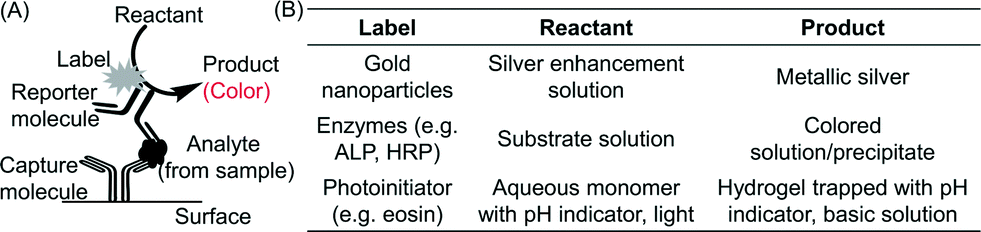 | ||
| Scheme 1 Colorimetric sensing mechanisms in a sandwich immunoassay. (A) Capture molecules immobilized on a surface bind to an analyte present in a sample. A reporter molecule that also specifically binds the analyte is either directly or indirectly (e.g. through streptavidin–biotin binding) labeled with an agent capable of producing a colorimetric product. (B) Labels such as gold nanoparticles, enzymes and photoinitiators can be used to generate a colorimetric readout. Gold nanoparticles are widely used commercially for direct visualization on nitrocellulose membranes without any silver deposition. We found that on pure cellulose surfaces such as the chromatography paper used in our study, visualization using gold nanoparticles required silver deposition (see ESI†). | ||
In order to evaluate only the effect of the colorimetric method on the readout, we kept the binding events constant and used biotin–streptavidin binding to vary the colorimetric detection method in the immunoassay. In enzymatic reactions, we used horseradish peroxidase (HRP) label with two different substrates, i) DAB/H2O2 – a mixture of 3,3-diaminobenzidine (DAB) and hydrogen peroxide (Scheme 2A), and ii) TMB/H2O2 – a mixture of 3,3′,5,5′-tetramethylbenzidine (TMB) and hydrogen peroxide (Scheme 2B) and alkaline phosphatase (ALP) label with BCIP/NBT – a mixture of nitro-blue tetrazolium (NBT) and 5-bromo-4-chloro-3-indolyl phosphate (BCIP) (Scheme 2C). With gold nanoparticle label, we used a silver enhancement solution to deposit metallic silver on the paper surface (Scheme 2D), and in PBA we used eosin as a label and a pH indicator, phenolphthalein, as a visualization agent (Scheme 2E).14
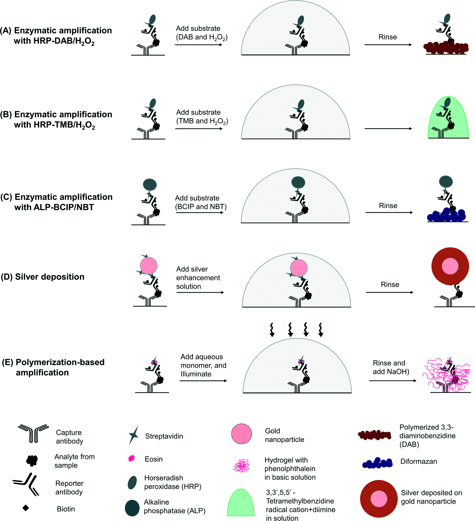 | ||
| Scheme 2 Schematic of the colorimetric sensing mechanisms tested in the study. (A) Enzymatic amplification using horseradish peroxidase with 3,3-diaminobenzidine and hydrogen peroxide mixture as substrate. DAB is oxidized to a free radical and polymerizes as a precipitate. (B) Enzymatic amplification using horseradish peroxidase with 3,3′,5,5′-tetramethylbenzidine (TMB) and hydrogen peroxide mixture as substrate. TMB is oxidized to a cation free radical (blue) and diimine (yellow), resulting in blue, green and yellow shades depending on the extent of reaction. (C) Enzymatic amplification using alkaline phosphatase with a mixture of BCIP/NBT as substrate. ALP catalyzes the formation of an insoluble diformazan product that precipitates on the surface of the paper. (D) Silver deposition, catalyzed by gold nanoparticles. The gold nanoparticles on the surface act as nucleation sites for deposition of metallic silver from the solution onto the surface. (E) Polymerization-based amplification. Photoinitiator molecules present on the surface, when irradiated with light in the presence of a monomer solution, initiate the formation of a hydrogel. A pH indicator trapped in the hydrogel during the polymerization allows visualization by addition of a base. | ||
Different colorimetric methods also differ in the hue‡ of the color produced, as well as the visible intensity§ of the colorimetric readout. Both these qualities can impact the ease of accurate interpretation by a user. A recent field test of a colorimetric paper-based test identified matching different hues to the color bar guide as the most challenging part of the test.5 In addition, weaker intensity of color makes it difficult to visually differentiate positive tests from negative tests.11–13 Therefore, the metric used to compare different colorimetric methods needs to be chosen carefully. Quantification in RGB color space, which is the most commonly used method to quantify the data obtained from colorimetric tests,17 does not capture the effect of hue and intensity on visual perception and is unsuitable for comparison between different colorimetric methods. Analysis in CIE 1931 color space coordinates provides a useful method to compare different colors with each other.18,19 Additionally, CIELAB color space, which is derived from CIE 1931 coordinates, has been designed to be linear in human perception,20 and is used as a measure of perceived visual contrast.21
In this work, we tested different concentrations of the label (Scheme 2) for each of the colorimetric methods and chose the concentrations that maximized the visible difference in color between the positive and the negative controls. Using these optimal concentrations, we documented the appearance of the colorimetric readout with time on both the negative and positive samples. We also recorded the colorimetric result of each method at its optimal readout time for a dilution series of analyte. The results were imaged with a cellphone and the colorimetric intensity was quantified in RGB color space to measure the calculated limit-of-detection (LoD). We also quantified the contrast perceptible to a user by analyzing the data from dilution series in CIELAB color space.
2. Experimental section
2.1. Preparation of paper surfaces
Paper surfaces were prepared for the assays by reaction with 30 mM sodium (meta) periodate (NaIO4) for two hours at 65 °C to oxidize the hydroxyl groups in cellulose to aldehyde groups, as described previously.14 The modified paper was washed with water, allowed to dry, and printed with a mask containing circular wax-free regions, 3 mm in diameter, surrounded by dark regions using a commercial solid ink Xerox ColorQube 8570 printer. The printed paper was heated to allow the wax (ink) to melt and penetrate through the paper22 to create isolated hydrophilic, unprinted regions surrounded by hydrophobic barriers. Each hydrophilic region can then be used independently and is referred to as a ‘test zone’ in the rest of the text. The paper was stored in a desiccator until further use.2.2. Preparation of reagents
Eosin was covalently coupled to streptavidin (SA) and reporter antibody (a mouse anti-PfHRP2, Clone 45) through reaction of the isothiocyanate group of eosin 5-isothiocyanate (EITC) with the lysine residues of the proteins. The reporter antibody was also covalently coupled to biotin using a sulfo-NHS biotinylation reagent (additional details of the conjugation reactions are provided in the ESI† Fig. S1–S3).The binding reactions on paper consisted of a capture antibody (a mouse anti-PfHRP2, Clone 44), an analyte (PfHRP2) and a modified reporter antibody (a mouse anti-PfHRP2, Clone 45). 2 μL of 1 mg mL−1 solution of the capture antibody was immobilized on each test zone of the modified paper overnight in humid chamber (HC). 2 μL solution is sufficient to thoroughly wet the entire test zone. Therefore, the spot size in our immunoassays was identical to the area of the hydrophilic region and was constant for all the detection methods in the study. The excess antibody was washed with 1× phosphate buffered saline solution (1× PBS) and the test zones were blocked with 10 μL of 1× Tris-buffered saline for one hour. After washing with 1× PBS, each positive surface was contacted with 10 μL of a specified concentration of PfHRP2 in undiluted human serum, and each corresponding negative surface was contacted with 10 μL undiluted human serum without any PfHRP2 for 30 minutes in a HC. The surfaces were washed with 1× PBS and contacted with 5 μL of 50 μg mL−1 solution of biotin-conjugated reporter antibody for 30 minutes. The excess unbound reporter antibody was washed with 1× PBS and the surfaces were further treated according to the colorimetric method being used. The optimal concentrations for the antibodies were determined in the previous study.14
2.3. Generation of colorimetric results
Positive and negative surfaces prepared above were contacted with 10 μL solution of 5 μg mL−1 streptavidin alkaline phosphatase conjugate (SA–ALP) (range tested, 0.1–20 μg mL−1) or 5 μg mL−1 streptavidin horseradish peroxidase conjugate (SA–HRP) (range tested, 2–50 μg mL−1) for enzymatic amplification reactions, 10 μg mL−1 streptavidin–eosin (SA–eosin) conjugate for PBA (range tested, 5–20 μg mL−1) and streptavidin-20 nm gold conjugate (SA–AuNP) at OD = 0.6 (range tested, OD 0.3 and OD 0.6) for silver deposition for 10 minutes. The above solutions were made in 1% PBSA (1% bovine serum albumin in 1× PBS). The surfaces were washed with 0.1% Tween 20 in 1× PBS (0.1% PBST), 1× PBS, and diH2O in sequence and treated as described in the following sections. , where L, a and b are CIELAB coordinates of a positive surface and L0, a0 and b0 are CIELAB coordinates of negative control surface. Additional details of image processing are provided in the ESI† Tables S1 and S2.
3. Results and discussion
3.1. Effect of time on the appearance of color
We characterized the kinetics of the visualization step, i.e., the color-generating step for each of the colorimetric detection methods by imaging the surfaces with time and comparing the colorimetric response between the positive and negative surfaces (Fig. 1). We also tracked the change in intensity of the negative surfaces and the difference in intensity between the positive and the negative surfaces with time (ESI,† Fig. S6).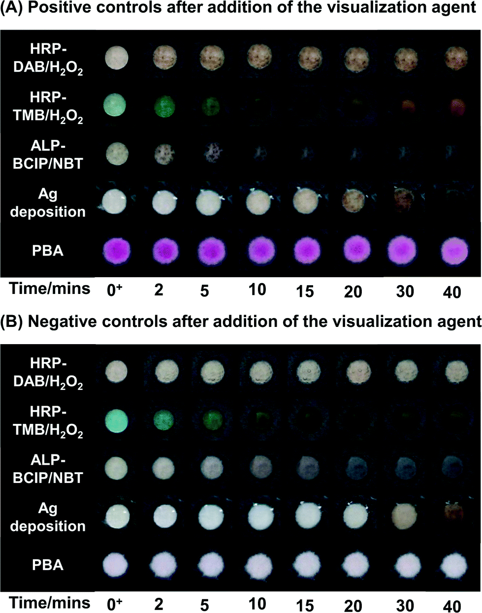 | ||
| Fig. 1 Time course for color generation on negative and the positive surfaces. Representative (A) positive (260 nM PfHRP2 in human serum) and (B) negative (undiluted human serum) surfaces were tested with different colorimetric methods and the visualization step for each method was imaged over time. For enzymatic reactions t = 0 was the time when the substrate solution was added to the surface, for silver deposition t = 0 was the time when silver enhancement solution was added to the surface, and for PBA t = 0 was the time when the basic solution was added to the surface. | ||
For enzymatic reactions, each enzyme-substrate pair produced its own characteristic set of hues and the appearance of the surface depended on the time of contact of the substrate with the surface. When DAB/H2O2 (a colorless solution) was chosen as the substrate for HRP, the colorimetric response was the appearance of a reddish-brown color (Fig. 1). On these surfaces, the maximum change in intensity occurred on the positive surfaces within the first five minutes. After five minutes, the color continued to become darker on both positive and negative surfaces, but very slowly. The result was that the difference between positive and negative surfaces increased during the first five minutes and then remained constant (ESI† Fig. S6A). Based on these results, eight minutes was chosen as the optimal time for color development for the HRP-DAB/H2O2 system. When TMB/H2O2 (a pale yellow solution) was chosen as the substrate for HRP, on initial contact the color turned blue on negative surfaces and bluish-green on positive surfaces. With time, the color changed to various shades of blue, green and yellow on both the positive and negative surfaces. (Fig. 1A and B) This complex colorimetric behavior was a result of the presence of two different oxidation states of TMB, a blue cationic radical and a yellow diimine form.23 The difference between these hues can be quantified using image analysis (ESI† Fig. S6B). The quantification showed that the difference between the positive and the negative surfaces was highest at the initial time of contact of the substrate and the positive surfaces were distinguishable from the negative surfaces up to 10 minutes. However, as indicated by the images in Fig. 1A and B, this difference was not clearly discernible by the unaided eye. To interpret the results using HRP-TMB system, a user needs to differentiate between shades of blue, green, and yellow while these hues are changing rapidly with time. Therefore, despite the fact that both DAB and TMB produce a quantifiable difference between positive and negative surfaces, the hues of the color readout make DAB a better choice of substrate than TMB for visual analysis and TMB was not used in further characterization.
The reaction of ALP with BCIP/NBT substrate (a pale yellow solution) led to the formation of a grayish-purple color on the surfaces. The rate of appearance of color on negative surfaces was slower than the rate of appearance of color on the positive surfaces, but both the negative and positive surfaces became significantly more colored with time (Fig. 1A and B). This colorimetric behavior resulted in the existence of a narrow time interval (3–5 minutes) for maximizing the difference between positive and negative surfaces (ESI† Fig. S6C).
The silver enhancement solution was originally colorless and on its contact with the positive surfaces, a reddish-brown color appeared slowly over the first 20 minutes (Fig. 1A). On negative surfaces, a visible light-brown color appeared between 25 and 30 minutes (Fig. 1B) due to self-nucleation of silver from the silver enhancement solution. Therefore, as was the case with ALP-BCIP/NBT, there was an optimal time, t = 25 minutes, for which the difference between the positive and the negative surfaces was the highest (ESI† Fig. S6D). In addition, the time for the beginning of self-nucleation of silver from the silver enhancement solution could be significantly shortened from ∼25 minutes to ∼10 minutes by exposure to ambient indoor light during the day (ESI† Fig. S7). While AuNPs are known to generate a visible color by themselves, i.e., without silver deposition for immunoassays on nitrocellulose membranes, we found that on chromatography paper used in this study, 20 nm AuNPs were insufficient to generate enough contrast to be seen by the unaided eye even when they were used at a high concentration of OD = 0.6 (ESI† Fig. S8). It is possible to increase the concentration of gold nanoparticles further, but even at OD = 0.6, the SA–AuNP conjugate contributed more than 70% to the cost of a single test (ESI† Tables S3 and S4).
In PBA, the visualization step was the addition of the basic solution to the surface. The color appeared as soon as the basic solution was added, indicating that there was no waiting time for the appearance of color (Fig. 1A); the color persisted for more than 40 minutes if the surface was laminated to prevent evaporation and during this time the appearance of the negative surfaces did not change (Fig. 1B, ESI† Fig. S6E). It should be pointed out that the visualization step in PBA is dependent on the presence or absence of a hydrogel on the surface, which is controlled by the duration of illumination (ESI† Fig. S9).
PBA fundamentally differs from the other colorimetric methods because of separation of the signal amplification and visualization steps. The minimum waiting time is determined by the illumination time, which is a design variable, and once determined, it remains fixed for a given light source, sample type, and monomer formulation.14 The signal amplification cannot continue in the absence of light, therefore an automated timing switch removes the requirement of manual time-keeping and intervention by a user. The visualization step for PBA does not involve any waiting time since the color develops as soon as the base is added (Fig. 1A).
3.2. Limit of detection
In order to determine the effect of the colorimetric method on the calculated limit-of detection (LoD), we tested surfaces with decreasing concentrations of PfHRP2, ranging from a maximum concentration of 260 nM to a minimum concentration of 0.2 nM, using HRP-DAB/H2O2, ALP-BCIP/NBT, silver deposition and PBA. For each of the colorimetric methods, the development of color was allowed for the optimal times determined from Fig. 1. After the optimal times for the enzymatic reactions and silver deposition, the surfaces were washed with water to stop the development of color and were allowed to dry before imaging, as is commonly reported in the literature.10,11 For PBA, the surfaces were imaged just after addition of the basic solution. For each of the colorimetric methods, the results containing the dynamic range are shown in Fig. 2 along with representative images. The images of negative control replicates and the replicates across the full PfHRP2 concentration range that was tested for all methods are shown in ESI† Fig. S10 and S11, respectively. The calculated LoD of each method was obtained by fitting a sigmoidal curve to the corresponding RGB intensity values and determining the minimum concentration of PfHRP2 required to produce a value that is greater than the average value of the negative surfaces by at least three times the standard deviation of the values of the negative surfaces. Since the immunoassay binding steps are the same for all four methods, the differences in the calculated LoD are a direct result of the colorimetric method. The LoD values were 0.32 nM, 0.15 nM, 6.9 nM, and 6.2 nM for HRP/DAB-H2O2, ALP/BCIP-NBT, PBA and silver deposition, respectively. RGB intensity values are commonly used for analyzing data obtained from color images in diagnostic tests.17 However, different ways of comparing the RGB intensity values of positive surfaces with the negative surfaces, while producing the same overall trend, can result in very different absolute values (ESI† Fig. S12). Therefore, RGB intensity values are a valuable tool for quantifying colorimetric results from a single test, but are not useful to describe how easy it is for a user to interpret the results of a colorimetric test or to compare different methods with each other.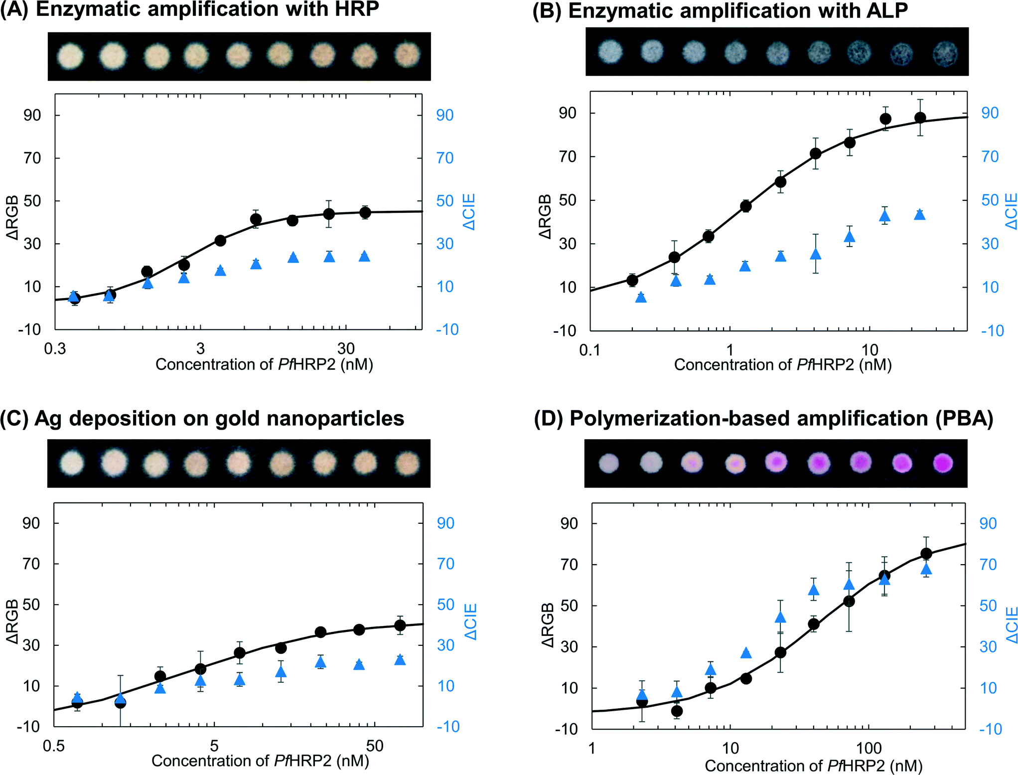 | ||
| Fig. 2 Quantifying the colorimetric results. A dilution series of PfHRP2 concentrations was tested with four different colorimetric methods, (A) enzymatic amplification with HRP-DAB/H2O2, (B) enzymatic amplification with ALP-BCIP/NBT, (C) silver deposition on gold nanoparticles, and (D) polymerization-based amplification. The surfaces in A), B) and C) were washed after 8 min, 4 min, and 25 min of addition of DAB/H2O2, BCIP/NBT and silver enhancement solution, respectively and allowed to dry before imaging. The surfaces in D) were imaged right after the addition of the basic solution. For each method, both ΔRGB and ΔCIE values were calculated. The LOD was calculated by fitting the ΔRGB values (black) to a sigmoidal curve (solid line) and determining the minimum concentration of PfHRP2 that would give a ΔRGB value that is greater than the ΔRGB value from the negative controls by at least three standard deviations of the negative controls. At least eight replicates were used to calculate the standard deviation of the negative controls (ESI† Fig. S10). The Each data point is an average of three replicates and the error bars are standard deviations. | ||
3.3. Quantifying ease-of-perception
In addition to the image analysis in RGB color space, we also analyzed the results from the dilution series in the CIELAB color space. We converted each image into CIELAB color space and calculated the ΔCIE values of positive surfaces compared to the corresponding negative surfaces (Fig. 2). CIELAB color space is designed to be linear for human perception20 across the entire visible spectrum. Therefore, the value of ΔCIE, i.e., the distance between any two points in the CIE color space, is a measure of the ease with which an average observer can differentiate between those two points,21 irrespective of the hue of the transition. The larger the value of ΔCIE between two different surfaces, the easier it is for an observer to differentiate between them. Therefore, unlike ΔRGB values, the absolute ΔCIE values have a physical meaning and can be compared across different colorimetric methods.To determine how easy it is to visually distinguish positive surfaces from negative surfaces near the calculated LoD, we specifically looked at the ΔCIE values for the surfaces tested with a concentration of PfHRP2 just above the calculated LoD. Representative images of positive and negative surfaces for each of the four methods are shown in Fig. 3A–D. Comparison of images with their corresponding ΔCIE and ΔRGB values (Fig. 3E) confirms that the magnitude of ΔCIE values is a better indicator of visual perception than ΔRGB values. The numbers indicate that near the LoD, the positive results for ALP and HRP are twice as difficult for a user to identify with the unaided eye as the positive results for silver deposition and four times as difficult to identify as the result for PBA. Therefore, even though the quantification in RGB color space puts the LoD of enzymatic methods as approximately an order of magnitude lower than silver deposition and PBA, the contrast at these LoD values is low. Since PBA results were clearly distinguishable by unaided eye at concentrations tested just above the calculated LoD, the average ΔCIE value of PBA results at 7.2 nM was taken as the baseline to define ‘visual LoD’; the HRP-DAB/H2O2 method, ALP-BCIP/NBT method, and silver deposition method generated similar contrasts at ∼4.1 nM, ∼1.3 nM, and ∼13 nM, respectively.
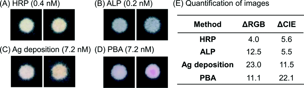 | ||
| Fig. 3 Quantification of perception near the limit-of-detection. For each colorimetric method, (A) enzymatic amplification with HRP-DAB/H2O2, (B) enzymatic amplification with ALP-BCIP/NBT, (C) silver deposition on gold nanoparticles, and (D) polymerization-based amplification, a positive surface (image on the right) tested with PfHRP2 concentration just above the calculated LoD is shown along with the corresponding negative control (image on the left). The images are taken under the same conditions as in Fig. 2. (E) Average ΔRGB and ΔCIE value for the surfaces shown is tabulated. ΔCIE values show a better correlation with perceived difference between the positive and negative surfaces as compared to ΔRGB values and indicate that positive PBA results near LoD are almost twice as easy to perceive as silver deposition results near LoD and almost 4 times as easy to perceive as the results from the enzymatic amplification methods. | ||
It should be noted that the ΔCIE values for analysis have been obtained from the images taken with a cellphone that stores the images in RGB format. The RGB color scale is device dependent; therefore the CIE coordinates obtained do not represent the true color of the surfaces, but represent the appearance of the images captured in this work. Variables such as the device used, the state of the surface (wet/dry) and lighting14 can significantly affect the appearance of the image and the absolute values of the red, green and blue channels in captured images (ESI† Fig. S13 and S14). Therefore, all images used for analysis were taken with the same device under similar lighting conditions.
To verify that the maximum magnitude of ΔCIE values does not depend on the hue of the readout, we used the absolute values of the red, green and blue channel intensities from the experiments, extrapolated them to obtain more saturated hues with the same color transitions as given by HRP-DAB/H2O2 or silver deposition, ALP-BCIP/NBT and PBA and verified that ΔCIE values can indeed be higher than the maximum values seen experimentally in Fig. 2. An example of the color transitions observed in this study at a ΔCIE value of 50 is shown in ESI† Fig. S15. Fig. S15† shows that the perception of color on a surface can also be affected by the background color, i.e., the color of the wax printed on the paper surfaces.
3.4. Discussion of alternative detection strategies
In this work, we have primarily focused on colorimetric detection methods that are most often reported for cellulose-based paper devices with a focus on their performance in low-resource settings. We independently assessed the effect of four detection methods on the limit of detection and ease-of-perception of the resulting colorimetric result. It should be noted that the lateral flow immunoassay literature provides several strategies to modify the colorimetric response of the methods that we have discussed by increasing the density of labels on the surface and/or combining different labels. Parolo et al.,24 combined the gold nanoparticle based detection with enzymatic amplification in a lateral flow immunoassay for a model system and reported improvement in LoD and contrast over the use of gold nanoparticles alone. Xu et al.25 reported loading gold nanoparticles on silica nanorods, Ge et al.26 reported linking several gold nanoparticles through DNA probes, and Choi et al.27 reported using two nanoparticle conjugates to increase the density of gold nanoparticles on the surface and improve the sensitivity of the assay. While the results from lateral flow assays on nitrocellulose cannot be directly translated to vertical flow assays on cellulose surfaces, these studies provide examples of strategies that can possibly be used to enhance performance in colorimetric paper-based tests. These strategies need to be further evaluated for ease-of-use in field settings.With the advent of low-cost readers, other detection methods such as electrochemical detection, chemiluminescence, electrochemiluminescence, and fluorescence might become feasible for cellulose-based immunoassays in low-resource settings. A rigorous comparison of any other detection method with the amplification methods used in our study would require the use of same binding molecules since the binding affinity of the biomolecules used in an assay also affects the LoD.28 While the evaluation of all the above methods on a common assay was beyond the scope of this work, a recent review by Capitán-Vallvey et al.17 summarized the analytical performance of many such methods reported in the literature.
4. Conclusions
Colorimetric detection methods enable diagnostic tests that are otherwise not feasible in RLS. In a previous study, we developed a polymerization-based amplification method for colorimetric detection in a paper-based immunoassay for use at the POC. However, different binding reagents, imaging techniques and methods of quantification used across the literature did not allow a meaningful comparison between this new method and existing colorimetric methods. In this work, we rigorously compared PBA with colorimetric methods based on the activity of two widely used enzymes, HRP and ALP, as well as readouts based on silver deposition, catalyzed by AuNPs in a common paper-based immunoassay. The use of a common immunoassay allowed us to examine the effect of each detection method on assay sensitivity and the ease-of-perception of the readout. We also highlighted the importance of time keeping on the colorimetric readout for some of the enzymatic reactions and for silver deposition. The results are summarized in Table S5.†All of the methods function well with accurate time keeping and appropriate positive and negative controls in the laboratory setting. However, for ALP-BCIP/NBT and silver deposition, we found that the time window for optimal colorimetric readout, i.e., time after positive surfaces are colored but before negative surfaces become visibly colored, was very narrow. The narrow optimal window necessitates accurate time keeping to prevent false positives that occur when reaction times are greater than the optimal time and false negatives that occur when reaction times are less than optimal time. For use in the intended POC setting, the requirement of accurate time keeping becomes more difficult and less desirable as the optimal times increase, e.g. from 4 minutes for ALP-BCIP/NBT to 25 minutes for silver deposition.
When colorimetric results can be quantified and negative controls are available, both the enzymatic methods have a calculated LoD of more than one order of magnitude smaller than PBA and silver deposition. However, at concentrations close to the calculated LoD of enzymes, it becomes increasingly difficult to visually differentiate positive surfaces from negative controls. In the field use of colorimetric tests, negative controls are not available and interpretation of a colorimetric readout is visual. Therefore, methods that can quantify visual perception of color would provide a better prediction of performance of a test in a field setting. We found that analysis of images in CIELAB color space provided a helpful framework in this direction and allowed us to define visual LoD for all methods. The visual LoD for PBA was similar to the calculated LoD, but for enzymatic amplification and silver deposition, the visual LoDs were much higher.
We have demonstrated that for a colorimetric test, the mechanism used to generate color has a significant effect on the outcome of the test and each method has its own set of optimal conditions for accurate interpretation. By specifically highlighting those conditions for some of the reported colorimetric methods, we anticipate that this study will help researchers and users choose the methods that are most suited to their particular needs. We want to highlight that the results of this study represent the best-case scenario for each method and the performance and optimal readout conditions in field settings might change depending on the stability of the labels and differences in environmental factors such as temperature, humidity, and exposure to light should be investigated. In addition, we hope that our study will motivate future efforts to develop novel colorimetric methods for POC devices that are designed to overcome field-use constraints by providing greater visual contrast and minimal dependence of color on time.
Acknowledgements
We acknowledge support from the Jonathon Whitney Fund and a Haas Family Fellowship in Chemical Engineering (SL), and a Reed Award (HS). We also thank Prof. George W. Whitesides for discussions that led to this project.References
- A. K. Yetisen, M. S. Akram and C. R. Lowe, Lab Chip, 2013, 13, 2210–2251 RSC
.
- V. Gubala, L. F. Harris, A. J. Ricco, M. X. Tan and D. E. Williams, Anal. Chem., 2012, 84, 487–515 CrossRef CAS PubMed
- N. P. Pai, C. Vadnais, C. Denkinger, N. Engel and M. Pai, PLoS Med., 2012, 9, e1001306 Search PubMed
- E. W. Nery and L. T. Kubota, Anal. Bioanal. Chem., 2013, 405, 7573–7595 CrossRef CAS PubMed
- A. A. Kumar, J. W. Hennek, B. S. Smith, S. Kumar, P. Beattie, S. Jain, J. P. Rolland, T. P. Stossel, C. Chunda-Liyoka and G. M. Whitesides, Angew. Chem., Int. Ed., 2015, 54, 5836–5853 CrossRef CAS PubMed
- A. W. Martinez, S. T. Phillips, G. M. Whitesides and E. Carrilho, Anal. Chem., 2010, 82, 3–10 CrossRef CAS PubMed
- C. D. Chin, V. Linder and S. K. Sia, Lab Chip, 2007, 7, 41–57 RSC
- E. Miller and H. D. Sikes, Nanobiomedicine, 2015, 2, 6 Search PubMed
- World Health Organization, Malaria rapid diagnostic test performance: Summary results of WHO product testing of malaria RDTs: Round 1-5 (2008-2013), 2014 Search PubMed.
- C.-M. Cheng, A. W. Martinez, J. Gong, C. R. Mace, S. T. Phillips, E. Carrilho, K. A. Mirica and G. M. Whitesides, Angew. Chem., 2010, 122, 4881–4884 CrossRef
- R. C. Murdock, L. Shen, D. K. Griffin, N. Kelley-Loughnane, I. Papautsky and J. A. Hagen, Anal. Chem., 2013, 85, 11634–11642 CrossRef CAS PubMed
- M. N. Costa, B. Veigas, J. M. Jacob, D. S. Santos, J. Gomes, P. V. Baptista, R. Martins, J. Inácio and E. Fortunato, Nanotechnology, 2014, 25, 094006 CrossRef CAS PubMed
- K. Abe, K. Kotera, K. Suzuki and D. Citterio, Anal. Bioanal. Chem., 2010, 398, 885–893 CrossRef CAS PubMed
- A. K. Badu-Tawiah, S. Lathwal, K. Kaastrup, M. Al-Sayah, D. C. Christodouleas, B. S. Smith, G. M. Whitesides and H. D. Sikes, Lab Chip, 2015, 15, 655–659 RSC
- K. Kaastrup and H. D. Sikes, Lab Chip, 2012, 12, 4055–4058 RSC
- A. M. Dondorp, V. Desakorn, W. Pongtavornpinyo, D. Sahassananda, K. Silamut, K. Chotivanich, P. N. Newton, P. Pitisuttithum, A. M. Smithyman, N. J. White and N. P. J. Day, PLoS Med., 2005, 2, e204 Search PubMed
- L. F. Capitán-Vallvey, N. López-Ruiz, A. Martínez-Olmos, M. M. Erenas and A. J. Palma, Anal. Chim. Acta, 2015, 899, 23–56 CrossRef PubMed
- L. Shen, J. A. Hagen and I. Papautsky, Lab Chip, 2012, 12, 4240–4243 RSC
- A. K. Yetisen, J. L. Martinez-Hurtado, A. Garcia-Melendrez, F. da Cruz Vasconcellos and C. R. Lowe, Sens. Actuators, B, 2014, 196, 156–160 CrossRef CAS
- CIE, Technical Report: Clorimetry, 2004, 3rd edition Search PubMed.
- M. A. Livingston, J. H. Barrow and C. M. Sibley, Proc. - IEEE Virtual Real., 2009, pp. 115–122 Search PubMed.
- E. Carrilho, A. W. Martinez and G. M. Whitesides, Anal. Chem., 2009, 81, 7091–7095 CrossRef CAS PubMed
- P. D. Josephy, T. Eling and R. P. Mason, J. Biol. Chem., 1982, 257, 3669–3675 CAS
- C. Parolo, A. de la Escosura-Muñiz and A. Merkoçi, Biosens. Bioelectron., 2013, 40, 412–416 CrossRef CAS PubMed
- H. Xu, J. Chen, J. Birrenkott, J. X. Zhao, S. Takalkar, K. Baryeh and G. Liu, Anal. Chem., 2014, 86, 7351–7359 CrossRef CAS PubMed
- C. Ge, L. Yu, Z. Fang and L. Zeng, Anal. Chem., 2013, 85, 9343–9349 CrossRef CAS PubMed
- D. H. Choi, S. K. Lee, Y. K. Oh, B. W. Bae, S. D. Lee, S. Kim, Y. B. Shin and M. G. Kim, Biosens. Bioelectron., 2010, 25, 1999–2002 CrossRef CAS PubMed
- K. Kaastrup, L. Chan and H. D. Sikes, Anal. Chem., 2013, 85, 8055–8060 CrossRef CAS PubMed
Footnotes |
| † Electronic supplementary information (ESI) available. See DOI: 10.1039/c6lc00058d |
| ‡ Hue is defined according to the wavelength of the color (for e.g. red, green, orange, violet, etc.). |
| § The lightness or darkness of a colorimetric readout. |
| This journal is © The Royal Society of Chemistry 2016 |