
Experimental evaluation of elemental behavior during LA-ICP-MS: influences of plasma conditions and limits of plasma robustness†
J.
Fietzke
* and
M.
Frische
GEOMAR Helmholtz Centre for Ocean Research Kiel, Wischhofstr. 1-3, 24148 Kiel, Germany. E-mail: jfietzke@geomar.de; Fax: +49 431 600 2924; Tel: +49 431 600 2106
First published on 20th October 2015
Abstract
Matrix effects are one of the frequently observed and discussed issues challenging the accuracy of LA-ICP-MS results. The specific role of the ICP as a source of elemental fractionation seems not fully understood. We report the results of an experiment using six internationally available reference materials (five silicates, one carbonate) measured under 11 different plasma conditions. The thermal/energetic state of the plasma was estimated based on the ratio of 38Ar+ and 40Ar2+ ions. We show that element specific behavior (volatile vs. refractory) dominates at cool but vanishes under hot plasma conditions. For robust (hot) plasma conditions matrix-tolerance seems to be achieved. Additionally we address the problem of matrix-load with respect to the plasma conditions. We've estimated practical limits for the amount of matrix which can be introduced into the ICP without significantly changing the plasma conditions.
1 Introduction
Since its introduction in 1985 LA-ICP-MS has experienced a dynamic development.1 It has become an accepted versatile tool for in situ analysis of solid samples.2,3 To date the number of publications reporting new applications in different scientific disciplines e.g. earth, material or bio-medical sciences has increased from year to year. While the majority of publications report results from applied studies the investigation of fundamental processes and problems of LA-ICP-MS needs also to continue.4 The previous work focussed a lot on the laser side, greatly improving the understanding of e.g. particle formation and transport.5,6 Interest is now shifting towards the ICP and could merge with the fundamental work on plasma conditions carried out using liquid introduction ICP-MS and modelling studies.Several problems are inherent in ICP-MS compromising accuracy and precision of the analytical results:
- Interferences: spectral overlap of isobaric ions, molecular (poly-atomic cluster) ions or doubly charged ions.
- Elemental fractionation: element-specific differences of the ion yield (depending on e.g. ionization potential, melting and vaporisation temperature).7–9
- Mass bias: mass-dependent fractionation of ions related to e.g. “space-charge effect” and ion optical design.10–12
In addition the mentioned major problems are influenced by the operating conditions (“plasma conditions”),13 stability of the instrumental tuning and response curve (“drift problem”),14 the major element composition of the particular sample (“matrix effect”)7,15,16 and the amount of material introduced (“mass-load effect”).17 A comprehensive review of the massive work done so far is beyond the scope of this paper.
Different strategies have been developed over the years to deal with the different mentioned challenges and allow for sensitive, precise, reproducible and accurate analyses. To eliminate/reduce poly-atomic cluster interferences collision/reaction cells are commonly used in quadrupole-ICP-MS and variable mass resolution has been applied using Sector-Field-ICP-MS.18–20 To handle problems of matrix-effects/elemental fractionation e.g. matrix-matching or mathematical correction methods have been developed.21 The influence of applied laser wavelength22 or pulse duration (ns- vs. fs-laser systems) has been studied and has contributed greatly to reducing matrix-related problems.23
Despite the work done so far the actual processes responsible for elemental fractionation in the ICP appear not to have been fully understood. How does the plasma contribute to the matrix-effect or why does the response of a particular element depend on the composition and amount of the accompanying matrix introduced into the plasma?
In this paper we report the results of a series of tests carried out to contribute additional information to this fascinating field. Our starting points have been the following considerations: the energetic/thermal condition of the plasma directly influences many of the problems mentioned before. For example the vaporisation and ionization of the sample aerosol or the formation of cluster ions are considered to be directly related to plasma temperature. As the ICP is a quite flexible ion source different combinations of operating conditions (rf power, gas flows, sampling depth) result ultimately in a particular energetic/thermal condition of the plasma at the place where it is sampled for spectral analysis. An indicator for the plasma condition should be based on the ionization degree (ID) of the plasma i.e. the ID of Ar. For tests of the fractionation effect within the ICP the mass spectrometer should only be the observational tool for the plasma, while the laser-ablation unit is used to supply the plasma with defined amounts of compositionally known material. Both, laser-ablation unit and the mass spectrometer, need to be operated close to their optimal conditions. Systematic changes in the measured spectra acquired under different plasma conditions may provide further information about the origin of the effects mentioned as problems before. And finally, we may find criteria to minimize them.
2 Experimental
2.1 Test layout
The experiment has been carried out using a Nu Instruments ATTOM HR-ICP-MS (with standard Ni cones: sampler 0.9 mm; skimmer 0.6 mm) coupled to a Coherent Lambda Physics GEOLAS pro 193 nm excimer laser ablation system equipped with the manufacturer's standard ablation cell (volume ∼ 50 ml). The instrumental parameters of both, LA and ICP-MS are summarized in Table 1.| Coherent GEOLAS pro 193 nm ArF excimer | ||
|---|---|---|
| Silicate standards | USGS-MACS3 | |
| Fluence | 5 J cm−2 | 2 J cm−2 |
| Spot size | 32 μm | 44 μm |
| Repetition rate | 10 Hz | 5 Hz |
| Number of pulses | 150 | 75 |
| Ablation mode | 2 × 15 s spot ablation, 50 s laser paused | |
| He cell gas flow | 0.55–0.66 l min−1 | |
| Nu Instruments ATTOM HR-ICP-MS | |
|---|---|
| Rf power | 1000 W |
| Cool gas | 17.5 l min−1 |
| Auxiliary gas | 0.56–1.03 l min−1 |
| Sample gas | 0.55–1.03 l min−1 |
| Tuning | Max. intensity of 36Ar (Faraday cup) |
| Data acquisition | 5 sweeps per cycle (1.1 s), linked mode (fast magnet scan with electrostatic deflection, ion counter, automatic attenuation) |
To obtain results which later can be related clearly to particular sources, processes or parameters, in our case the influence of the sample matrix on elemental fractionation in the plasma, the ablation parameters used (5 J cm−2 laser fluence, 10 Hz repetition rate, 32 μm spot size) have been kept constant. The number of shots per spot has been limited to 150 to keep the aspect ratio < 1. The ablation cell gas flow of He (99.999% purity) was kept in a narrow range of 0.55–0.66 l min−1 and only fine-tuned to provide a fast sample wash-out (tested for sharp signal pulses, when ablating at 2 Hz). This should minimize influences of down-hole fractionation, particle formation and transport within and out of the ablation cell and keep the amount of material injected into the plasma relatively constant.
He coming from the cell was mixed with Ar (sample) gas after the ablation cell using a concentric glass mixing device. No further signal smoothing device has been applied. The mixed He–Ar sample gas was transported to the ICP using ∼3 m PFA tube (inner diameter 2 mm). The ICP was operated at 1000 W and the cool gas flow kept constant at 17.5 l min−1. The sampling depth was set once in the beginning of the test and not changed afterwards. Only the vertical and horizontal torch positions were slightly adjusted to capture the maximum sample signal.
To provide different thermal conditions in the core region of the plasma the auxiliary and sample Ar gas flows were systematically adjusted jointly over a range between 0.56 and 1.03 l min−1. Obviously, this procedure will also be accompanied by changes in the initial velocity of injected particles. Both effects impact jointly i.e. increased sample gas flows provide stronger cooling and higher particle velocities, both hindering vaporization of particles and ionization of the sample. For this test we are only interested in the resulting plasma condition.
Each plasma condition applied during the experiment required the mass spectrometer ion optics to be tuned for maximum transmission. As ion kinetic energies in the plasma and in the interface will change according to the thermal/energetic state of the plasma, primarily the extraction potential needed readjustment. This tuning was done using 36Ar measured using the Faraday cup of the mass spectrometer. Focusing on Ar has the advantage of needing no sample to be ablated, thus being independent on any preliminary decision with respect to standard material used or preferred isotope used for tuning which otherwise could bias the test results. In our opinion by applying a common criterion this procedure ensures the test measurements are carried out under comparable tuning conditions. The mass spectrometer is used as an observational tool of the plasma operated under different conditions.
The 36Ar intensity achieved after optimizing the mass spectrometer could be considered as a proper indicator of plasma temperature as the Ar ionization degree (ID) primarily depends on the temperature. To a lesser degree the temperature influences the plasma density, too, reducing the intensity gain per ID increase with increasing temperature.
While initially the experiment was performed setting up the plasma to provide different 36Ar intensities it appears more practical for the presentation of results to refer to the intensity ratio of 38Ar+ and 40Ar2+ dimer ions (both measured using the electron multiplier during the experiment) which again is primarily dependent on the plasma temperature, but compensates for the above mentioned density effect. Additionally, this ratio should be a more general parameter, easily transferable from one instrument to the other and less affected by the particular tuning, or instrumental equipment used (including applicable ion acceleration potential, cone type, interface pressure, slit setting, detector efficiency, etc.).
For presentation purposes we use a normalized Ar index (NAI) defined here as:
| NAI = 2·38Ar+/40Ar2+ |
The scaling factor of 2 was added to obtain a NAI of 1 for the plasma state providing a Th oxide formation rate of ThO/Th = 0.005 at our instrumental setup. The scaling factor may differ for other labs depending on residual O abundance in the gas supply (e.g. He purity). At this plasma state our instrumental setup provided a 38Ar+ intensity of 7 × 10⁷ cps and 40Ar2+ (amu80) intensity of 1.4 × 10⁸ cps, respectively, which refers to a total Ar+/Ar2+ intensity ratio of about 800 for a NAI of 1. Plasma states covered by our experiment ranged from NAI of 0.024 for the cold to about 32 for the hot.
We consider the NAI as a robust and practical indicator. It is based on the actual condition of the plasma at the site of ion sampling regardless of how this condition has been achieved by a complex combination of e.g. rf power and gas flows. Further details of the tuning procedure applied are provided in the ESI.†
2.2 Standards used and data collection
Six internationally available, fairly well characterized standard materials have been used for the test, five silicates and one carbonate. The chemical composition (except for oxygen) of these standards is shown in Fig. 1.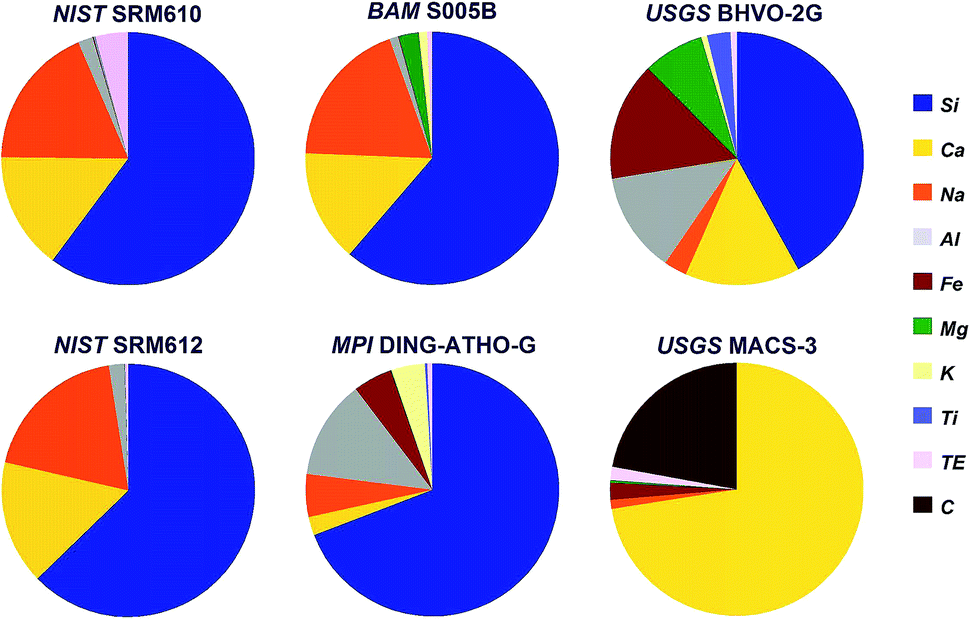 | ||
| Fig. 1 Chemical composition (except for oxygen) of the standards used during the experiment. TE covers all other trace elements. | ||
Three of the standards, soda-lime glasses NIST SRM610 and -612 (ref. 24) and BAM S005B25 resemble quite similar major elemental composition, but differ significantly in their trace element concentrations. To cover a larger compositional range rhyolite glass (MPI DING-ATHO-G)26 and komatiite glass (USGS BHVO-2G)27 have been used. Finally, shifting from silicates to carbonates USGS MACS-3 (ref. 28) has been included into the experiment, too.
Each individual set of measurements consisted of the same ablation sequence of the standards. Prior to the measurements all standards have been pre-ablated applying 80 shots using a spot size of 120 μm. To compensate for potential drifts standards have been measured in the following order: NIST SRM610, NIST SRM612, BAM S005B, MPI DING ATHO-G, USGS BHVO-2G, USGS MACS3, NIST SRM610, USGS MACS3, USGS BHVO-2G, MPI DING ATHO-G, BAM S005B, NIST SRM612, NIST SRM610. Pauses of 50 s have been applied between each standard, as well as at begin and end of each sequence. Silicate standards were ablated at two consecutive spots (no pause) applying each time 150 shots using 32 μm spot size, a fluence of 5 J cm−2 and a repetition rate of 10 Hz. To provide sufficiently smooth signals the ablation parameters for carbonate standard USGS MACS3 needed to be modified to 75 shots using 44 μm spots, a fluence of 2 J cm−2 and a repetition rate of 5 Hz.
Measurements were performed using the linked scan mode of the ATTOM, a fast magnet scan mode supported by synchronized electrostatic deflection, covering the full mass range scanning up and down every 0.22 s. Data were collected for 100 different isotopes in 5 sweeps per 1.1 s total integration time per data point (cycle) using the ion counter switching automatically between two modes: unattenuated for signal intensities < 7 × 10⁶ cps and attenuated for intensities > 7 × 10⁶ cps. Attenuation results in an ion beam intensity reduction by a factor of about 450, efficiently protecting the ion counter while reproducibly collecting data for high intensity signals. During the experiment only abundant isotopes of major elements (e.g.23Na, 27Al or 28Si) were measured in attenuated detector mode.
The 100 isotopes measured are covering 74 elements of interest in the sample, represented by at least one isotope, plus diagnostic species (plasma ions, cluster ions e.g. oxides and argides as well as multiply-charged ions).
Regarding integration time per isotope during each cycle of 1.1 s one needs to consider the consequence of the scan mode used, sequentially collecting data on 100 isotopes. During one cycle each isotope is measured on average for only about 10 ms. For some isotopes sandwiched between adjacent isotopes of interest this will be even shorter, for others without adjacent isotopes of interest this could be longer due to the performance characteristics of the automated linked scan mode of the ATTOM.
The complete data collection sequence took about 21 min. Up to 8 such measurement runs have been performed for each plasma state (11 different ones).
2.3 Data evaluation
The raw data of both ablation intervals of each of the standards within on run have been combined, integrating the signals to compensate for potential (linear) drifts. Further data evaluation for isotope ratio calculation has been performed applying the linear regression slope (LRS) method. This method has been originally developed for transient Sr isotope data from LA-MC-ICP-MS and later successfully transferred to other transient data applications.29,30This method makes use of the simultaneous responses of the different isotope signals. A particular isotope ratio is derived directly from the slope of the linear regression fit of both isotopes' intensities.29Fig. 2 displays examples from a NIST SRM610 measurement from this experiment. All four displayed isotopes exhibit strong linear correlations when plotted e.g. vs.43Ca. Intensities start from their respective on-top-zero baseline and evolve along a straight trend to the point of maximum signal and back to the baseline.
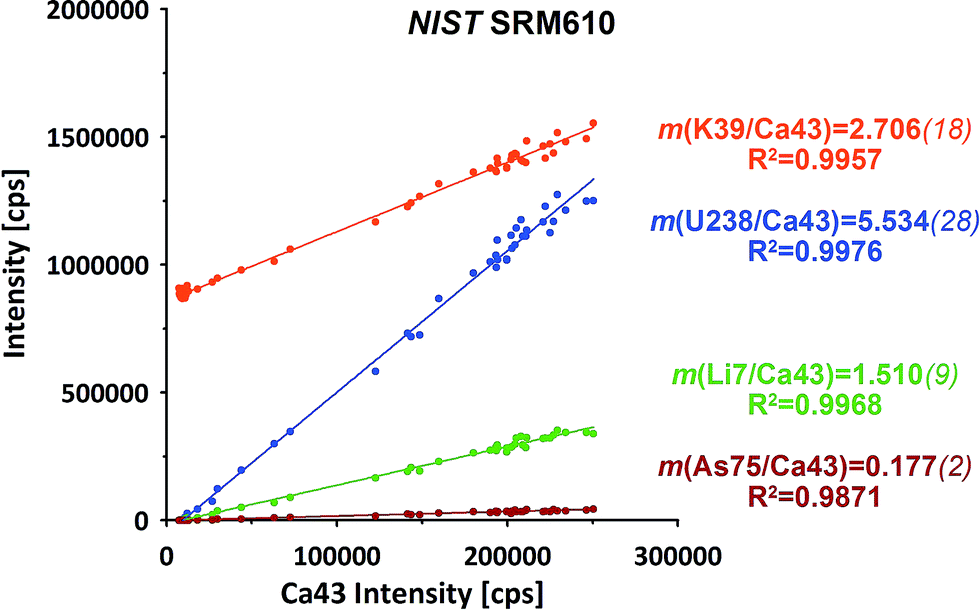 | ||
| Fig. 2 Examples for the simultaneous responses of the isotope intensities during ablation of NIST SRM610. Ratios of particular isotopes are derived from the slope m of the linear regression (LRS method). Italic values in brackets represent the SE of m. | ||
Down-hole fractionation, mass load effects or changes in the particular baseline would be visible as deviations from the fit line, but are not observed here.
3 Results
3.1 Plasma ion compositional changes
How does the composition of the ICP plasma change through the course of the experiment?We've measured the intensities of the dominant ions for the different plasma states (without sample ablation) using the Faraday cup. The results are provided in Fig. 3 displayed as the relative amounts of the four major plasma ion species. At the cold end (NAI = 0.024) the plasma is by far dominated by ArH+ cluster ions (measured as 40ArH+). Ar+ ions (calculated based on measured 36Ar+ using natural Ar isotope abundances), are even less abundant than O+ ions (measured as 16O+).
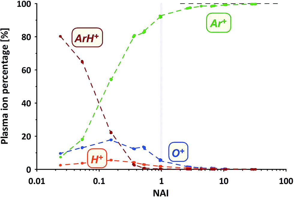 | ||
| Fig. 3 Plasma ion partitioning related to plasma conditions indicated by NAI. | ||
With increasing NAI (increasing plasma temperature) the dominance of ArH+ vanishes and is gradually over taken by Ar+ ions. Still ions of O and H contribute significantly to the ion population. At NAI of 1 (equivalent to ThO/Th = 0.005) the plasma consists of about 92% Ar+, 6% O+, 2% H+ and about 0.3% ArH+ ions, respectively. Further increasing NAI leads to an even stronger dominance of Ar+ ions, accounting for 99.7% of the ICP plasma ions at NAI of 32. This shows the gradual transition from an ArH+ ion dominated, via an O+ and H+ ion contaminated Ar plasma and finally into an almost pure Ar plasma. Multiply-charged Ar ions (not shown here) follow the expected systematic, increasing in intensity with increasing NAI.
Commonly applied criteria to evaluate the plasma condition are the formation rates of thorium oxide and doubly-charged Ca ions. While the first should decrease with increasing NAI (increasing plasma temperature), the second is considered to increase due to higher temperatures providing more energy for the 2nd ionization of Ca. The systematic change of both values (Ca doubly-charged measured as amu21.5/amu43) from measurements of NIST SRM610 using the ion counter are shown in Fig. 4.
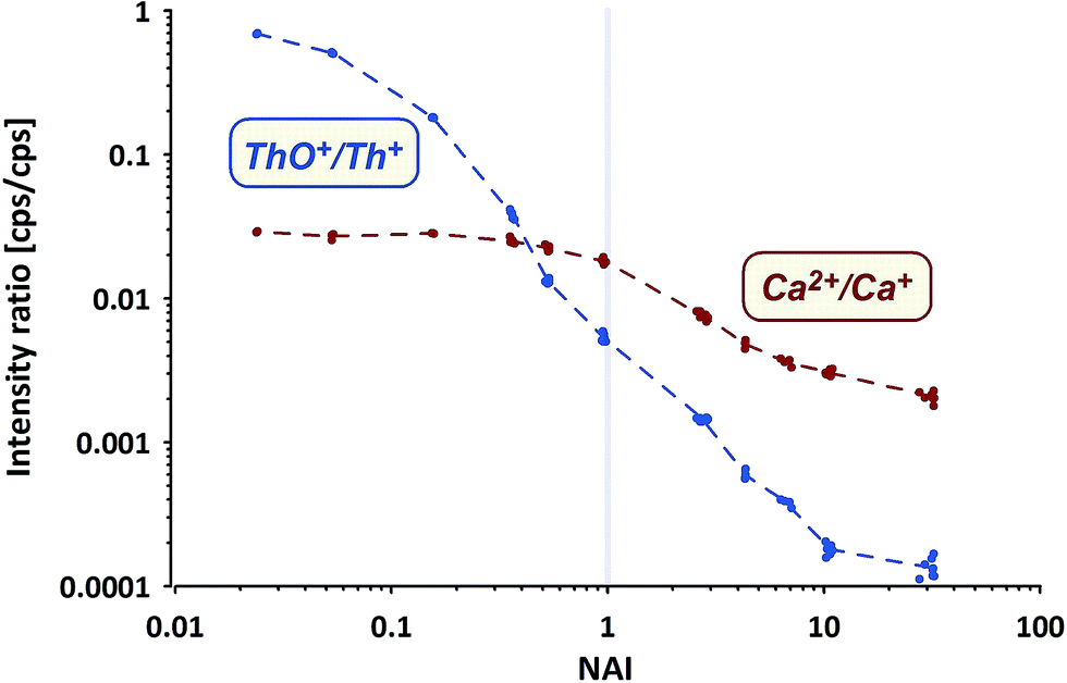 | ||
| Fig. 4 Th oxide and Ca doubly-charged ion formation rates measured using NIST SRM610. | ||
ThO+ (ion counter data) behaves as expected, gradually declining with increasing NAI. At the cold end (NAI = 0.024) Th oxide formation is as high as ThO+/Th+ = 0.7, displays a value of 0.005 at NAI = 1 and declines further to <0.0002 at the hot end (NAI = 32) of the tested range. The lowest ThO+/Th+ ratio achieved in our experiment is more than one order of magnitude lower than so far reported as lower limit.31
In contrast Ca doubly-charged ions behave unexpectedly. The formation rate stays fairly constant at 0.028 for the NAI range between 0.024 and 0.16 and declines to 0.018 at NAI = 1 (ThO+/Th+ = 0.005). Against intuition (higher temperatures should support the formation of doubly-charged ions) Ca doubly-charged formation rate decreases with further increasing NAI (rising plasma temperature) and displays a value of 0.002 at the hottest plasma state tested.
While both trends shown in Fig. 4 derive from NIST SRM610 data, the other standards provided identical trends. The surprising observation of declining Ca2+ formation with increasing plasma temperature could be partially explained by a change in the mass response of the spectrometer caused by a stronger space-charge effect defocusing the ion with the lower mass to charge ratio (amu21.5) stronger than the one with higher m/z (amu43). On the other hand Ba and U also show a doubly-charged formation rate of only 0.01 at NAI = 32 (hottest plasma conditions tested).
3.2 Systematic changes of elemental relative responses
In Fig. 5A the measured isotope to 43Ca ratios calculated using the LRS method (see Section 2.3) are shown for 208Pb, 209Bi, 232Th and 238U. While a certain pattern is already visible, the picture is disturbed because the mass response curve (ion detection efficiency vs. ion mass) of the instrument changes depending on the tuning at different NAIs. In general our instrument's sensitivity for the highest NAI's during this experiment is reducing for high masses relative to 43Ca with increasing plasma temperatures. This is either caused by imperfect tuning or limitations of the ion optics originally designed for operation of the instrument at colder plasma. Therefore, this should not be mistaken with the before mentioned reduction seen for lighter masses caused by increased defocusing in the interface by stronger space charge effects. To compensate for this effect we exchange the reference isotope 43Ca (large mass difference) by 238U (neighboring mass). Fig. 5B shows the trends of the 4 isotopes of interest, normalized now to 238U. Interestingly, the trends become significantly more ordered. Relative to 238U, both 208Pb and 209Bi, display declining trends in contrast to 232Th. Differing strongly in the low-NAI (high ThO+ formation, cool plasma) region the response trends approach constant values at high NAI (>10, lowest ThO+, hot plasma). In other words at high plasma temperatures the relative responses of Pb, Bi, Th and U do not change with variations in NAI anymore. To us this appears to be a natural fix-point for further renormalizing the response trends.
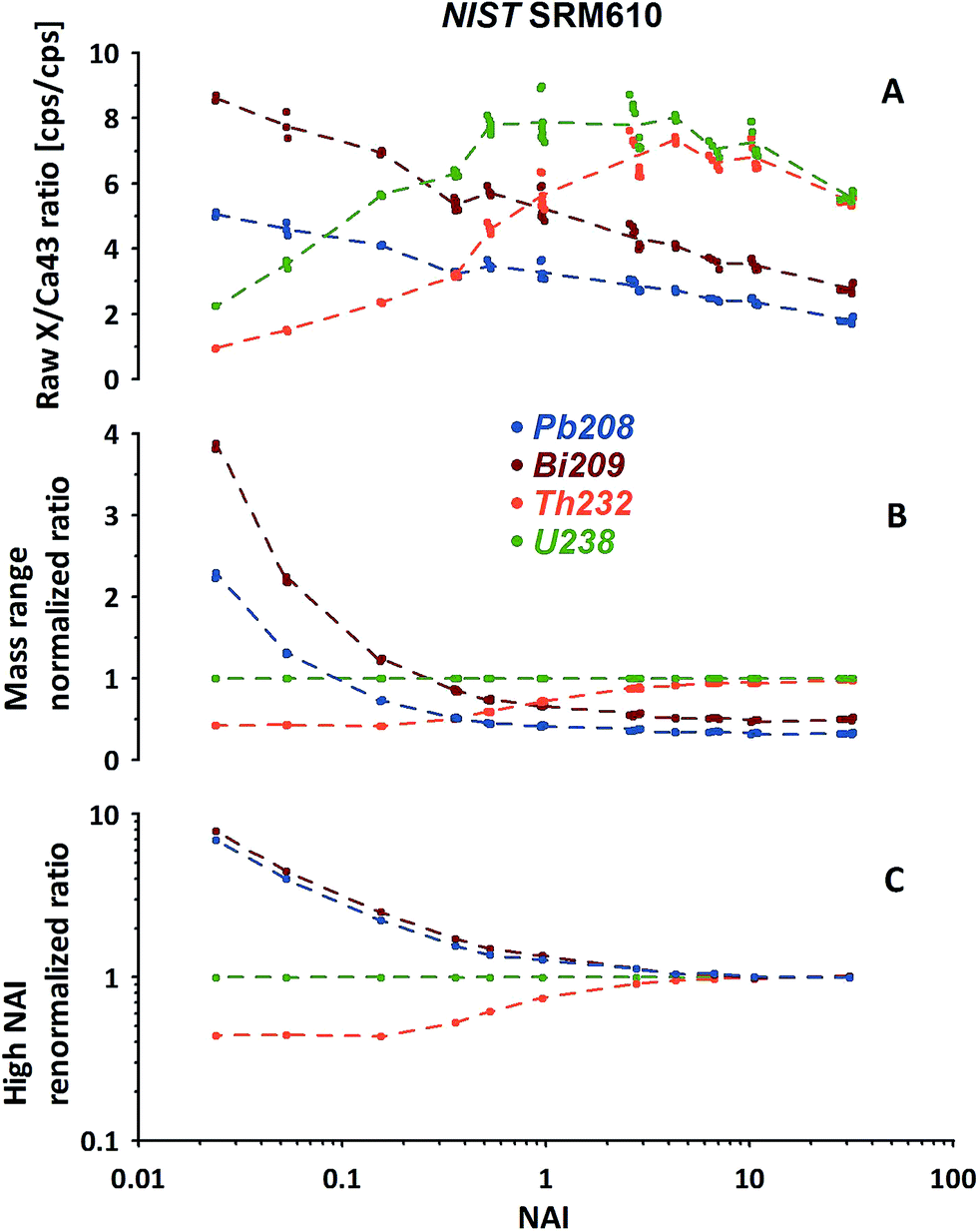 | ||
| Fig. 5 Example of the 2-step renormalization procedure based on high-mass-range isotopes measured using NIST SRM610. (A) Raw isotope/43Ca ratios derived from LRS data evaluation. (B) Change of the reference isotope from 43Ca to 238U to focus on the high mass range. (C) Renormalization of each elemental response curve shown in (B) to the high NAI (>10) end. Note: Y axis change from linear (A and B) to logarithmic (C). | ||
Results of renormalizing each elemental response trend to its respective mean value obtained from NAI > 10 data are displayed in Fig. 5C. As this 2nd renormalization step compensates for differences in the elemental concentrations (and isotopic abundances of the isotope used to represent a particular element) in the respective standard the resulting trends can be interpreted as differences of elemental behavior at differing plasma states. In our example Pb and Bi appear to behave quite similarly. Both elements' responses (sensitivity) decrease with increasing NAI (rising plasma temperature) relative to U. Th in contrast shows a fairly constant relative response to U at low and high NAI with a transition in the intermediate region increasing towards higher NAI.
Regarding the use of ThO as an indicator of the plasma condition, we've made the following observation carrying out an additional test. The helium used as ablation cell gas (99.999% purity) had been further cleaned online using a liquid N2 cryo trap. Trace contaminations of e.g. O2, CO2, CH4 should be efficiently removed from the He. While the oxide formation rate (ThO+/Th+) was reduced by almost a factor of 3 we did not see a significant change in the elemental response (described before and in the following text) at a given NAI. This indicates, oxide formation is a secondary effect depending on both, the availability of oxygen and the conditions in the central plasma channel. Thus, ThO+/Th+ is not a sufficiently robust indicator for the plasma condition and should be handled with care. Also, our observation implies the He is the main source of oxygen (note 2/3 removal after cryo-trapping using a fairly small trap volume). This is supported by the observation that oxygen intensities strongly correlate with the amount of He introduced. This could be easily seen, setting up different mixtures of Ar and He in the combined sample gas flow, resulting in similar NAI (keeping the sum of both flows about constant).
1st renormalization: to an isotope in the neighboring mass range and
2nd renormalization: to the respective high-NAI (hot plasma) value.
As can be seen from Fig. 6 (quite similar to Fig. 5C) our normalization reveals characteristic patterns within each group of elements displayed. In general the behavioral characteristics (relative responses) of elements differ massively for the NAI < 1 range. Element-specific differences vanish almost completely towards the highest NAI. At the first glance elements which display a relative intensity gain towards colder conditions (Pb, Bi, In, Cs, Ga, Rb, Na and K) are the ones more volatile than the respective normalization element, and those which lose intensity are the more refractory ones (Th, La, Ce, Y, Zr, V, Sc, Ti). At the second glance influences of polyatomic cluster ions can also be seen. The latter is most obvious for Fe and Sc in Fig. 6, suffering from hydrides and oxides at low plasma temperature (high formation rate of poly-atomic cluster ions).
 | ||
| Fig. 6 Examples of relative elemental responses of groups of elements after the 2-step-renormalization (data from NIST-SRM610). Each group renormalized to an isotope of neighboring mass. | ||
The above mentioned more volatile elements belong to the group of elements which are reported in the literature to have a Fryer's fractionation index > 1 and a low vaporization index.32,33 In contrast the just mentioned, more refractory ones belong to those elements reported to have a fractionation index = 1 and a high vaporization index.32,33 While Fryer's fractionation index mostly represents the laser-induced down-hole fractionation, i.e. elemental fractionation during progressive spot ablation, it is considered to be caused by re-deposition of non-stoichiometric debris around and melting within the ablation crater.8,32 In our experiment, performed under identical ablation conditions, we can rule out effects of laser induced fractionation to be responsible for the observed systematic behavior of elements. Instead we consider the elements' characteristic behavior is a clear image of gradual changes of fractionation related to the plasma conditions present.
The most important observation is, that at hot plasma conditions (NAI > 10), the elements' relative responses become insensitive to further changing plasma conditions. This clear picture appears after the described re-normalization procedure but would hardly be fully recognizable based on 43Ca-normalized data.
To compare the results of different standards, focusing on the sensitivity of particular elements to changes in plasma conditions (variations of NAI) we use the first derivatives of the response curves for all measured isotopes relative to 43Ca (compare Fig. 6D). The results for NAI = 1 and NAI > 10 are shown in Fig. 7 (NIST SRM612 and BAM S005B not shown, as major element composition almost identical to NIST SRM610, for complete data see ESI†). Positive values indicate an increase and negative values a decrease in response relative to Ca with increasing NAI (rising plasma temperature) at a given point of the response curve.
 | ||
| Fig. 7 Derivatives of the responses to 43Ca vs. NAI for compositionally different standards used during the experiment plotted against respective isotopic masses, calculated for NAI = 1 (blue) and NAI > 10 (red). | ||
At NAI = 1 (blue symbols in Fig. 7), in accord to the results presented in Fig. 5 and 6, elemental responses display characteristic patterns related to their volatile/refractory behavior relative to Ca. Contributions from cluster ion interferences should only play a minor role (note, ThO+/Th+ = 0.005 at NAI = 1). Additionally, increasing NAI leads generally to a reduced response for the light elements, resulting in negative derivative values for NAI = 1. We interpret this as a preferential de-focusing of light elements with rising plasma temperatures probably as a result of an increased space charge effect in the interface from higher Ar+ ion beam intensities. At this plasma state (NAI = 1) the standards still show minor differences in their respective elemental sensitivity for changing NAI. This means, the plasma state is not sufficiently robust to allow for an accurate calibration of the results of one standard by another. Matrix-effects might be already small, but if the NAI (plasma condition) changes during ablation or changes differently for each standard, depending on the amount or composition of matrix introduced, the changes in elemental responses may differ between standards and samples. We think this can result in inaccurate calibrations as matrix tolerance is not yet achieved at NAI = 1 (ThO+/Th+ = 0.005).
At NAI > 10 (red symbols in Fig. 7) the picture has changed dramatically: the first derivatives all approach zero. The relatively largest, still very minor, deviations can be found for elements Te, S, I, Se, As, P, B, Zn showing volatile behavior (derivatives: −0.01 … −0.04). The observed changes imply the behavior of different elements has become practically independent of their respective volatility and is not sensitive to changing plasma conditions anymore. The isotope used for standardization can be freely selected as renormalization will not change the systematic. Considering this and the fact that all standards measured show this behavior we conclude at NAI > 10 the plasma state is robust. Even if different matrices or sample amounts change the NAI (which becomes less likely for higher NAI, i.e. hotter plasma anyway) the relative responses of the elements do not change significantly. At least for the matrices tested (three differently composed silicates and one carbonate) matrix tolerance seems to be achieved.
We think our observations point towards differences in the particle vaporization which appears to be incomplete at NAI = 1 fractionating the elements depending on their volatility. The degree of fractionation may differ depending on the matrix' main composition and properties (e.g. particle size distribution, thermal conductivity).
Previous studies also related the observed fractionation to incomplete vaporization of large particles.33,34 It had been shown that the particle size distribution produced by a particular LA system (e.g. 266 nm vs. 193 nm) had a strong influence on elemental fractionation. In contrast to such studies particle size distributions should not vary in our experiment. Instead we think the thermal gradient between injector of the torch and region of ion sampling gradually became steeper with rising NAI (lower sample and auxiliary gas flows, hotter plasma) shifting the point of complete vaporization closer and closer to the injector tip. After particle vaporization has been completed atoms and ions of both, sample and plasma, can equilibrate before sampling. For NAI > 10 particle vaporization appears to be complete, the fractionation in the plasma has stabilized. Further increase in NAI does not change the fractionation any more but results in a larger radial dispersion of sample ions before sampling, reducing the usable amount of sample ions as mentioned in previous studies.31
One could speculate if the process of particle decomposition is best described by gradual melting and vaporization or if, in the steep thermal gradient at NAI > 10, material is sputtered from the particle surface by Ar atoms and ions of high kinetic energy.
Another observation supports the assumed completeness of particle disintegration, which is the negligible deposition of material on the cones when running the ICP-MS under hot plasma conditions. To our knowledge this observation has so far not been reported. We do observe corrosion of the cone tips from atom and ion bombardment (by far dominated by Ar), but not the opposite (significant deposition). We think coatings may only form if the incoming beam of atoms and ions is sufficiently weak and remaining particulate matter can stick to the cone surface. For sure, also the limitation of the amount of ablated material as described in Section 3.4 contributes to this effect.
3.3 Elemental responses under hot plasma conditions
So far all results presented and discussed have been obtained without using the nominal concentrations of elements in the particular standards. We only assumed the standards to be sufficiently homogenous to investigate the relative responses of isotopes representing respective elements. The advantage of this approach is its applicability even if elemental concentrations are not well constrained or information is not available.Using published concentration data for the six standards used,24–28 the abundances of the representing isotopes and the measured isotope/43Ca ratios, we've calculated the elemental responses (intensity/ppm) for all measured elements. Ca, represented by 43Ca, is used as reference (response = 1). The results for three standards are provided in Fig. 8 (for complete data set see ESI†). For easier orientation the average of all 74 elements in the six standards measured are provided (grey curve). As elemental concentrations differ massively between different standards those averages have been calculated based on the error-weighted means of individual standards' results to reduce the influence of low concentration data.
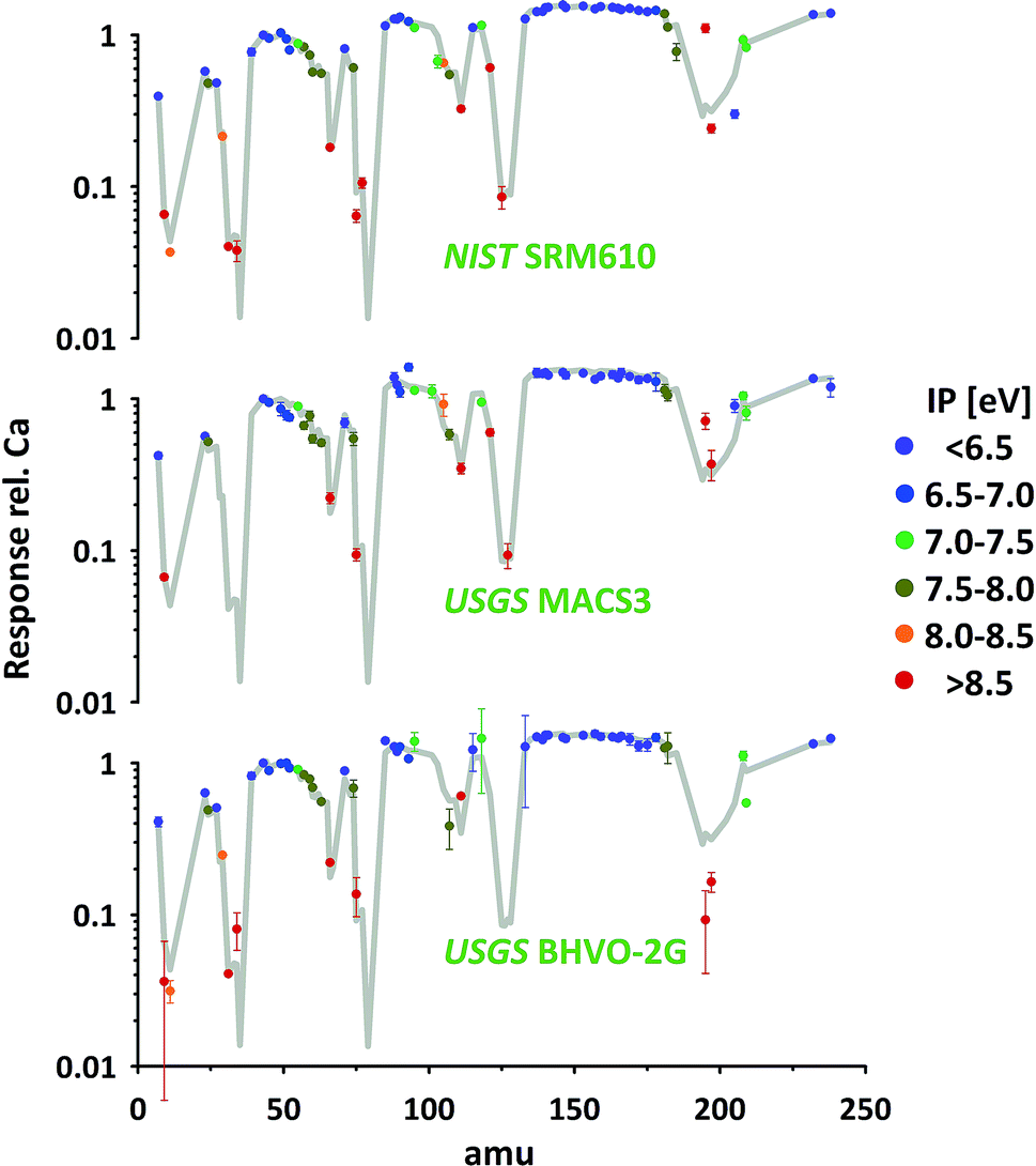 | ||
| Fig. 8 Responses of elements (intensity/nominal concentration) plotted according to representing isotope's mass for three of the standards investigated (Ca response = 1). Measurements performed under NAI > 30 condition. First ionization potential (IP) of elements was used for color-coding. Assuming 100% ionization for easy-to-ionize elements (IP < 7 eV, blue symbols) responses shown represent instrumental mass response curve. | ||
The average response curve shows a consistent trend for the easy-to-ionize elements (1st ionization potential IP < 7 eV). Assuming an ionization degree of about 100% for this group of elements this trend defines the mass response curve of our instrument during this test. Mass bias from space charge effects in the interface and imperfect tuning/focusing of the ion optics of the mass spectrometer mostly impacts on the light elements. This is leading to a gradual increase in elemental responses from e.g. Li, via Na and K to Rb. At this intermediate mass range the response curve forms a plateau and slightly decreases again from the heavy rare earth elements towards the heavy end (Th, U) of the mass spectrum. This decrease points towards imperfect tuning (it's a real not an ideal mass spectrometer) or limitations in the ion optic's which have probably been designed assuming lower plasma temperature as typical operation condition.
Relative to this response curve hard-to-ionize elements deviate towards lower responses (lower ionization degree) as shown in the literature.2 A systematic decrease is observed starting for elements having an IP of 7–8 eV and becomes stronger with further increasing IPs (e.g. 13.0 eV for Cl and 11.8 eV for Br). Validation of the observed systematic between 1st IP and ionization degree, while intuitively reasonable and frequently reported, critically depends on accurate information of nominal elemental concentration data for all standards used. The latter is challenging as the available concentration data for elements with IP > 7 eV are less well constrained.
As can be seen from Fig. 8 the data of the three standards (silicates and carbonate) displayed for the majority of elements agree well with the average curve. Within the limits of uncertainty these elements can be used to accurately calibrate one standard by the other. Significant discrepancies between the standards are observed for certain elements e.g. Pt (low concentration, high IP). As the elements' sensitivities on changing plasma conditions become identical for the different standards (see 3.2.3) observed discrepancies could point towards deviations between true and assumed concentrations.
Additionally, some elements seem to be not in accord with the general trend (lower response with increasing IP) e.g. B, Pd and Sb. Future studies are needed to further evaluate the robustness of the mentioned trend and to evaluate if discrepancies result from deviations between true and assumed standard concentrations. A detailed revision of standard concentration data is beyond this study's scope.
3.4 Limits of plasma robustness
In this remaining section we want to discuss practical limits of plasma robustness with respect to changes in the plasma composition resulting from the introduction of sample matrix ions. The work of Kroslakova and Günther revealed a clear influence of the mass load applied to the plasma on elemental fractionation.17We consider the plasma-related matrix effect as a change in the response of a sample isotope (representing an element) depending on the amount and composition of the accompanying sample matrix changing the plasma state. If the introduced material is not significantly changing the plasma conditions (energetically and compositionally) different samples (or standards) enter an identical plasma environment. On the contrary if the introduced material changes the conditions each introduced sample creates its own unique plasma condition. The more the plasma conditions differ between different materials introduced, the less comparable the measurement conditions. As a relatively simple criterion we use the ratio between the integrated matrix ions' and Ar ions' intensities MA = sum(Imatrix)/IAr acknowledging that this is a simplification not accounting for the actual mass response curve. To calculate MA for a particular measurement we have converted all measured intensities using the respective isotope abundances to account for the total amount of each element included (all matrix elements and Ar). E.g. if during a measurement a sample introduction results in MA = 0.1 this means during the time of sample data collection the plasma consists of 90% Ar ions plus 10% ions generated from the introduced matrix. We think such a case already is critical because:
- Sample data collection and gas blank determination are done under different conditions (the later may not be fully representative for the former to allow for an accurate background correction).
- Different samples or standards may not result in the same MA and even if they do, the composition of the 10% matrix ions may be different (e.g. silicate vs. carbonate).
To overcome this problem we see two possibilities, strict matrix-matching (or addition of a common matrix)17 or keeping the MA sufficiently low i.e. ensuring Imatrix ≪ IAr. Despite the fact that the first approach is commonly applied we think it is easier and more robust to aim for the second one. In particular matrix-matching is hard to achieve for unknown heterogeneous samples and may be problematic with respect to the above mentioned background issues.
For the second approach we need to find out, which MA's are occurring in our typical application and which upper limit shouldn't be exceeded. In a short additional test we've collected MA data at 5 different plasma states using NIST SRM610 (similar operational conditions as stated in 2.1, using spot sizes of 24 μm, 44 μm, 60 μm and 160 μm). The results are provided in Fig. 9 (left part). To visualize the gradual change in the plasma ion population, in the right sub-figure MA is converted into the relative proportion of argon and matrix ions changing from almost 100% Ar at low MA to about 90% matrix at MA = 10. From the displayed trend (red curve in right sub-figure) it appears to us that for MA < 0.01, i.e. <1% introduced total sample ions compared to Ar+, the matrix contribution is negligible. At the highest NAI tested in here MA stays below the just mentioned limit regardless of the applied spot size.
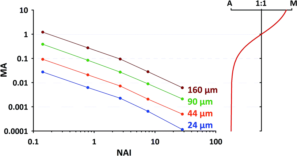 | ||
| Fig. 9 Left: Relationship between matrix-Ar-index (MA) and NAI for different amounts of ablated material (from different spot sizes); data from NIST-SRM610 measurements. Right: Relative proportion between Ar and matrix ions for different MA. | ||
As one can see from Fig. 9, for commonly applied intermediate spot sizes, MA enters the range above the limit of 0.01 at lower NAI. In our opinion gradually increasing MA above 0.01 can be interpreted as progressively “over-loading” the plasma, challenging its robustness and increasing the risk of matrix-dependent variable fractionation. We think to some extent this “plasma-over-loading” contributes to observed mass-load-effects and down-hole fractionation in the literature.8,17 In both cases MA changes during the application either step-wise (different mass-loads applied) or gradually (decreasing sample amount due to declining ablation yield). Further studies are needed to evaluate the usefulness of the MA index.
4 Conclusions
We think the described experiment can help to distinguish the influence of the plasma on elemental fractionation from processes during ablation (down-hole fractionation, particle size distribution) and in the mass spectrometer (changes of space charge effect, ion extraction and focusing).7–12,31,32 The previously observed mass-load effect can be attributed to changes of the plasma state when introducing sample amounts exceeding the limits of plasma robustness (MA < 0.01).17,35From the results of our experiment we conclude that tuning the ICP for hot plasma conditions (being close to ideal pure Ar plasma) provides more robust operating conditions for LA-ICP-MS (for tuning details see ESI†). The ratio of 38Ar+ to 40Ar2+ ions, referred in this paper as normalized Ar index (NAI) can serve as a relatively simple indicator to determine the achieved thermal/energetic plasma state. The systematic change in relative elemental responses with changing NAI indicates the volatile/refractory behavior of elements dominates under cool (low NAI) and gradually vanishes towards hot (high NAI) conditions. This is interpreted as a result of gradual vaporization of the sample aerosol. After vaporization has been completed elemental fractionation stabilizes and the elemental responses appear to exclusively follow the instrumental mass response curve and an ionization degree systematic defined by the first ionization potential (IP) of the elements. The latter needs further confinement as nominal concentrations of some elements (e.g. with high 1st IP or highly volatiles) may not be sufficiently well constrained.
The robustness of a particular application can be estimated by the proportion of matrix to Ar ions (MA index) following the assumption that background (gas blank), samples and standard measurements should be performed ideally under identical plasma conditions. The best approximation appears to be to target a MA value of <0.01 (i.e. less than 1% sample ions compared to Ar+) when the plasma state seems not to be significantly changed on the introduction of the matrix.
Hot plasma conditions combine improved matrix-tolerance, complete sample decomposition, high ionization degree and reduction of poly-atomic cluster ions (indicated by ThO/Th < 0.0002 and high NAI). Interestingly, a reduction of the formation of doubly-charged ions (e.g. Ca2+) is observed, too, and confirmed by relatively low formation rates of Ba2+ and U2+ under hot plasma conditions (NAI = 32). While observed for all standards investigated, the reason for the latter is intuitively not clear. This point needs further confirmation for other doubly-charged sample ions. Possibly, the fact that at high NAI the plasma consists almost exclusively of Ar ions, results in a massive reduction of possible reaction pathways for sample ionization. We might speculate that under these conditions collisional charge transfer from Ar+ ions is the dominating process of ionization.
The space charge effect is considered as highly stable at hot plasma conditions as the sample ions move through the interface and within the ion optical system as a minute addition to the Ar ion beam. Thus, the Ar ions define the space charge and “contamination” from sample ions will hardly affect it.
In general practical application of the whole approach is relatively simple. Robust plasma conditions with all above shown advantages can be achieved by a rigorous but controlled tuning for low sample and auxiliary gas flows while keeping efficient extraction and focusing of the mass spectrometer via readjusting the ion optics (first of all extraction lens). In the ESI† a detailed guideline for this tuning is provided. The operation under hot plasma conditions is robust and easy to maintain, day-to-day tuning is fairly reproducible once set up: gas flows need little to no readjustment and tuning (e.g. on Ar ion intensity) can be focused on the ion lenses with only small changes on a day to day basis. As deposition on the cones is negligible this part of maintenance (cone cleaning) is hardly needed, while replacing corroded cones every couple of month still is.
Of course there are also disadvantages. So far we have observed two. One is a reduction of sensitivity depending on the particular NAI (30% @ NAI = 10; 50% @ NAI = 30). The hotter the plasma the more the sample is diluted already within the plasma (higher temperature leads to lower density and a broadening of the sample ion distribution in the plasma). We think this disadvantage is acceptable and outcompeted by the mentioned advantages. A second disadvantage relates to the hardware. The Ar ion beam is significantly stronger and impacts more heavily on internal apertures and slits reducing their respective lifetimes. We have already implemented modifications to our hardware (using now slits and exchangeable aperture insets made from tantalum). The manufacturers may follow this approach.
At the end of our conclusions we want to point out some questions which remain open in our opinion:
(1) Is the process of particle decomposition best described as melting/vaporization or do we face under high-NAI conditions a sputtering from the sample aerosol particle surface by impacting high-energy Ar atoms and ions?
(2) Is collisional charge transfer from Ar ions indeed the dominant process of sample ionization in the almost pure Ar plasma at high NAI conditions?
(3) How can we transfer our observation from LA-ICP-MS to liquid-introduction ICP-MS? (We consider the described systematics to be generally transferable, but this needs to be proven.)
(4) How can mass fractionation laws, used to correct isotopic ratios, be based on the real response curve of the instrument which for the larger mass range is clearly deviating from any of the described ideal systematics? If the mass response curve does not follow one of the typically applied fractionation laws (e.g. exponential or power law) for the full mass range, it can also be only an approximation for smaller parts of it.
Luckily, further questions arise from observations made, keeping curiosity alive…
Acknowledgements
The authors wish to express deepest gratitude to two anonymous reviewers who contributed massively to this manuscript. Their dedication of time and effort is highly appreciated and gratefully acknowledged. A great “Thank you!” also goes to all colleagues for invaluable discussions regarding all different kind of (LA)-ICP-MS-related issues over the years. At this point we also would like to acknowledge our deep respect and thankfulness to all people involved in establishing the GEOREM database. It is such a great service for our whole community! Brigitte Stoll is gratefully acknowledged for providing pieces of the MPI-DING glasses. Finally: All the best to our dear journal! 30 years of JAAS and so many more exciting years yet to come.References
- A. L. Gray, Analyst, 1985, 110, 551 RSC.
- D. Günther and B. Hattendorf, Trends Anal. Chem., 2005, 24, 255 CrossRef PubMed.
- C. A. Heinrich, T. Pettke, W. E. Halter, M. Aigner-Torres, A. Audetat, D. Günther, B. Hattendorf, D. Bleiner, M. Guillong and I. Horn, Geochim. Cosmochim. Acta, 2003, 67, 3473 CrossRef CAS.
- D. Günther, J. Anal. At. Spectrom., 2014, 29, 952 RSC.
- M. Guillong and D. Günther, J. Anal. At. Spectrom., 2002, 17, 831 RSC.
- D. B. Aeschliman, S. J. Bajic, D. P. Baldwin and R. S. Houk, J. Anal. At. Spectrom., 2003, 18, 1008 RSC.
- H. P. Longerich, D. Günther and S. E. Jackson, Fresenius. J. Anal. Chem., 1996, 355, 538 CAS.
- S. M. Eggins, R. L. Rudnick and W. F. McDonough, Earth Planet. Sci. Lett., 1998, 154(1–4), 53 CrossRef CAS.
- F. E. Jenner and H. S. C. O'Neill, Geochem., Geophys., Geosyst., 2012, 13, Q03003 Search PubMed.
- J. A. Olivares and R. S. Houk, Anal. Chem., 1985, 57, 2674 CrossRef CAS.
- S. H. Tan and G. Horlick, J. Anal. At. Spectrom., 1987, 2, 745 RSC.
- G. R. Gillson, D. J. Douglas, J. E. Fulford, K. W. Halligan and S. D. Tanner, Anal. Chem., 1988, 60(14), 1472 CrossRef CAS.
- I. Rodushkin, M. D. Axelsson, D. Malinovsky and D. C. Baxter, J. Anal. At. Spectrom., 2002, 17, 1223 RSC.
- M. M. Cheatham, W. F. Sangrey and W. M. White, Spectrochim. Acta, Part B, 1993, 48, E487 CrossRef.
- M. Gaboardi and M. Humayun, J. Anal. At. Spectrom., 2009, 24, 1188 RSC.
- J. Czas, K. P. Jochum, B. Stoll, U. Weis, Q. C. Yang, D. E. Jacob and M. O. Andreae, Spectrochim. Acta, Part B, 2012, 78, 20 CrossRef CAS PubMed.
- I. Kroslakova and D. Günther, J. Anal. At. Spectrom., 2007, 22, 51 RSC.
- J. S. Becker and H. J. Dietze, J. Anal. At. Spectrom., 1997, 12, 881 RSC.
- I. Feldmann, N. Jakubowski and D. Stuewer, Fresenius' J. Anal. Chem., 1999, 365, 415 CrossRef CAS.
- S. F. Boulyga and J. S. Becker, Fresenius' J. Anal. Chem., 2001, 370(5), 618 CrossRef CAS.
- K. P. Jochum, B. Stoll, K. Herwig and M. Willbold, J. Anal. At. Spectrom., 2007, 22, 112 RSC.
- M. Guillong, I. Horn and D. Günther, J. Anal. At. Spectrom., 2003, 18(10), 1224 RSC.
- Q. Z. Bian, J. Koch, H. Lindner, H. Berndt, R. Hergenröder and K. Niemax, J. Anal. At. Spectrom., 2005, 20, 736 RSC.
- S. A. Wise and R. L. Watters, National Institute of Standards and Technology Website, 2012, http://www.nist.gov/srm Search PubMed.
- U. Panne and R. Matschat, BAM Federal Institute for Materials Research and Testing Website, 2015, http://www.bam.de/en/certificates/special_materials/index.htm Search PubMed.
- K. P. Jochum, D. B. Dingwell, A. Rocholl, B. Stoll, A. W. Hofmann, S. Becker, A. Besmehn, D. Bessette, H.-J. Dietze, P. Dulski, J. Erzinger, E. Hellebrand, P. Hoppe, I. Horn, K. Janssens, G. A. Jenner, M. Klein, W. F. McDonough, M. Maetz, K. Mezger, C. Munker, I. K. Nikogosian, C. Pickhardt, I. Raczek, D. Rhede, H. M. Seufert, S. G. Simakin, A. V. Sobolev, B. Spettel, S. Straub, L. Vincze, A. Wallianos, G. Weckwerth, S. Weyer, D. Wolf and M. Zimmer, Geostand. Geoanal. Res., 2000, 24, 87 CrossRef CAS PubMed.
- R. Wolf and S. Wilson, USGS reference materials program, USGS, Fact Sheet, 2007, p. 3056.
- S. Wilson, USGS, MACS-3 certificate.
- J. Fietzke, V. Liebetrau, D. Günther, K. Gürs, K. Hametner, K. Zumholz and A. Eisenhauer, J. Anal. At. Spectrom., 2008, 23, 955 RSC.
- V. N. Epov, S. Berail, M. Jimenez-Moreno, V. Perrot, C. Pecheyran, D. Amouroux and O. F. X. Donard, Anal. Chem., 2010, 82, 5652 CrossRef CAS PubMed.
- Z. Wang, B. Hattendorf and D. Günther, J. Am. Soc. Mass Spectrom., 2006, 17, 641 CrossRef CAS PubMed.
- B. J. Fryer, S. E. Jackson and H. P. Longerich, Can. Mineral., 1995, 33, 303 CAS.
- H. R. Kuhn, M. Guillong and D. Günter, Anal. Bioanal. Chem., 2004, 378, 1069 CrossRef CAS PubMed.
- M. Guillong, H. R. Kuhn and D. Günther, Spectrochim. Acta, Part B, 2003, 58(2–3), 211 CrossRef.
- K. P. Jochum, D. Scholz, B. Stoll, U. Weis, S. A. Wilson, Q. Yang, A. Schwalb, N. Börner, D. E. Jacob and M. O. Andreae, Chem. Geol., 2012, 318–319, 31 CrossRef CAS PubMed.
Footnote |
| † Electronic supplementary information (ESI) available. See DOI: 10.1039/c5ja00253b |
| This journal is © The Royal Society of Chemistry 2016 |