
 Open Access Article
 This Open Access Article is licensed under a Creative Commons Attribution-Non Commercial 3.0 Unported Licence
Porous carbon derived from rice husks as sustainable bioresources: insights into the role of micro-/mesoporous hierarchy in hosting active species for lithium–sulphur batteries†‡
Maria K.
Rybarczyk§
ac,
Hong-Jie
Peng§
b,
Cheng
Tang§
bc,
Marek
Lieder
a,
Qiang
Zhang
*bc and
Maria-Magdalena
Titirici
*c
aChemical Faculty, Department of Chemical Technology, Gdansk University of Technology, 11/12 Narutowicza Str., 80-233 Gdansk, Poland
bBeijing Key Laboratory of Green Chemical Reaction Engineering and Technology, Department of Chemical Engineering, Tsinghua University, Beijing 100084, P.R. China. E-mail: zhang-qiang@mails.tsinghua.edu.cn
cSchool of Engineering and Materials Science & Materials Research Institute, Queen Mary University of London, Mile End Road, London, E1 4NS, UK. E-mail: m.m.titirici@qmul.ac.uk
First published on 23rd June 2016
Abstract
The exploration of natural resources as sustainable precursors affords a family of green materials. Exploring highly abundant and available biowaste precursors remaining from food processing throughout a scalable and cost-effective material synthesis path is highly important especially for new materials discovery in emerging energy storage technologies such as lithium–sulphur (Li–S) batteries. Herein, we have produced a series of carbon materials with hierarchical micro-/mesopores from a very cheap and abundant lignocellulosic bio-waste, namely rice husk. The carbonisation of the lignocellulosic fraction leads to the formation of micropores while the removal of the silica present naturally in the rice husk composition allows the formation of mesopores. We can easily tune the ratio of micropores to mesopores by simply tuning the synthesis conditions in order to achieve an optimal performance in Li–S batteries after sulphur infiltration into the resulting porous carbons. Our optimal cathode scaffold for Li–S batteries exhibited a high capacity of 1032 mA h g−1 at a current density of 0.1 C. An ultralow decay rate of 0.055% per cycle was achieved. The appearance of abundant micropores with a higher surface area renders a high initial capacity of sulphur to polysulphides; however, the sufficient mesopore volume is more vital for a lower cyclic decay, which is prerequisite for the generation of solid products and smooth ion diffusion. This work, besides reporting on an efficient method to produce efficient electrode materials from waste to be used in energy storage technologies also provides fresh insights into the required structural features to allow effective cathode materials for high-performance Li–S batteries.
1. Introduction
Porous carbon materials play an important role in adsorption,1 separation,2 catalysis,3 energy storage and conversion.4 In particular for electrochemical energy storage, porous carbon is under increasing investigation due to its high surface area, tailored porous structure, and tuneable surface properties.5,6 Among various electrochemical energy storage systems, lithium–sulphur (Li–S) batteries are particularly promising since they can afford a very high specific energy of 2600 Wh kg−1, which is 3–4 times higher than the current lithium-ion battery system.7,8 Besides, sulphur exhibits merits of low cost, natural abundance, and environmental friendliness when compared to commercial cathode materials such as LiCoO2. However, the practical application of Li–S batteries has been strongly hindered by the extremely low electrical/ionic conductivity of active materials, the dissolution and shuttling of reactive polysulphide intermediates, the collapse of electrode structures due to the volume expansion of sulphur cathodes and the dendritic growth of lithium anodes.7Immobilizing sulphur and polysulphides into porous carbon materials with desirable hierarchical pores has proved to be an effective and efficient strategy to resolve these problems.6 Liang et al. firstly employed hierarchical porous carbons (HPC) in Li–S batteries by chemically activating soft-templated mesoporous carbon and demonstrated the synergistic effect of bimodal pore systems.9 Many other HPC materials have been synthesized and adopted as sulphur immobilizers, including SiO2/surfactant co-templated carbon,10 mesoporous carbide-derived carbon,11 core/shell micro-/mesoporous carbon,12 and tailored hierarchical porous graphene.5,13,14
The micro-/mesopore hierarchy is regarded as one of the most important parameter for improving the battery performance. In hierarchical porous cathodes, the micropores (<2 nm) afford high surface area and abundant active sites for adsorption and interfacial reactions, while the mesopores (2–50 nm) endow a shorter pathway for the rapid migration of ions leading to high-rate performance. Generally, complex and multistep processes such as chemical activation15 coupled with templated-carbonisation,9,16 are employed to achieve such hierarchical micro-/mesopore structures. Recently, the use of natural resources, such as crab shell,17 pig bone,18 fish scale,19 kapok fiber,20 pomelo peel,21 fungi,22 and plane-tree bark,23 have been considered as sustainable precursors for the production of carbon materials with bioinspired hierarchical structures. If a sustainable and highly abundant source (over 100 million tons per year of rice husk globally) can be applied to produce hierarchical nanostructured carbon materials through scalable and cost-effective manufacturing processing, a green and sustainable material platform is then achieved to broaden their practical applications for advanced energy storage.24
In this contribution, rice husks, the hard protecting coverings of grains of rice, are selected as bio-resources to investigate their potential for the production of hierarchical carbon materials for Li–S battery cathodes. Rice husks are widely produced amounting to around 148.2 million tons in 2014.25 Some rice husks produced in American, Asian, and European countries are employed as building materials, fertilizers, insulation materials, and fuel, however, most of them burn with very low grade heat inducing heavy air pollution. It should be noticed that typical rice husks consist of cellulose (38%), hemicelluloses (18%), lignin (22%), and SiO2. This composition renders rice husk an ideal precursor with stable supply and uniformity for energy materials fabrication. In fact, rice husks have been applied as precursors for silica gel,26 activated carbon,27 and ingredients for lithium-ion batteries.28 Herein, we provide a facile methodology to produce rice husk derived carbons with interconnected mesopores and micropores. The as-obtained carbon materials are tested as conductive scaffolds for Li–S battery cathodes. Our approach allows easy control over the pore structures and composition of carbon materials from rice husks in order to probe their mechanism and understanding on the rational utilization of sulphur in a working Li–S battery.
2. Results and discussion
To allow a facile use of bioresources, rice husks were directly carbonized under an inert atmosphere at 900 °C to achieve an RHC-SiO2 sample. The SiO2 content was determined to be around 40%. The as-obtained products were impregnated into 4.0 M NH4HF2 solution to fully remove the SiO2 and achieve an RHC sample with a yield of 30%.To achieve abundant micropores on the rice husk derived carbons, hydrothermal carbonisation was first carried out at 230 °C, under which the cellulose is easily transformed into hydrothermal carbon materials with abundant micropores. An inert annealing at 900 °C was also carried out to guarantee an RHC-HT sample with excellent electrical conductivity and a yield of 25%.28,29 The conversion of biomass via the HTC process was previously described by Titirici et al.30
As shown in Fig. 1a, the RHC-SiO2 sample inherits a complex structure with a smooth appearance. The SiO2 content was determined to be 47% (Fig. S1‡). When SiO2 is removed by acid etching, the RHC becomes rougher as a proof of pore development (Fig. 1b). When the rice husks are hydrothermally carbonized firstly, a more porous structure can be already observed from the SEM micrograph of the RHC-HT sample (Fig. 1c), in contrast to the flake-like morphology of RHC shown in Fig. 1b. The TEM images further confirm the distinct porosities. The RHC-SiO2 sample exhibits a close-grained morphology and appears thick under TEM (Fig. 1d). In contrast, the RHC sample appears more transparent with obviously interlinked mesopores (Fig. 1e and f), indicating the removal of SiO2 and hierarchical few-layered carbon scaffolds.
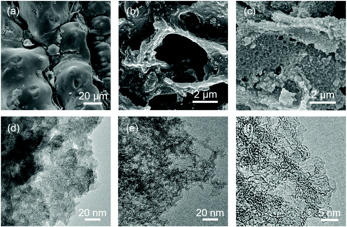 | ||
| Fig. 1 Morphology of rice husk derived carbon: SEM images of (a) RHC-SiO2, (b) RHC, and (c) RHC-HT. TEM images of (d) RHC-SiO2 and (e) RHC. (f) High-resolution TEM image of RHC. | ||
The structure of all carbon samples was further analysed by X-ray diffraction (XRD) (Fig. 2a). Two broad peaks appear at 21–27.5° and 42.5–44.3° for all samples. This indicates that the rice husk derived carbon materials are the combination of many turbostratic carbon domains. An empirical parameter (R), defined as the (002) peak-to-background ratio, is estimated in the range R = 1.37–1.95. R is used as an indicator of the number of carbon sheets arranged as single layer. When the R value is larger than 1, a high level of graphene nanosheets is stacked in parallel. The broad peaks at 21–27.5° of RHC are stronger than that of RHC-HT, indicating a large size of turbostratic carbon domains with few micropores. The SiO2 in the RHC-SiO2 sample is confirmed as the diffraction peak of quartz around 26.6° can be clearly observed.
 | ||
| Fig. 2 (a) XRD patterns and (b) Raman spectra of RHC-HT, RHC-SiO2, and RHC. | ||
The carbon–carbon bonding of the rice husk derived carbon was further probed by the Raman spectra (Fig. 2b). All materials exhibit outstanding D and G bands. The D band at ca. 1350 cm−1 usually belongs to the A1g breathing mode of the disordered graphite structure, and the high-frequency G band at ca. 1580 cm−1 is assigned to the E2g stretching mode of graphite. The G band reflects the structure of the sp2 hybridized carbon atom. The height of the D band increases upon the washing step in this work. The extent of the defects in carbonaceous materials upon surface modification is quantified by the intensity ratio of the D to G bands (ID/IG). The ID/IG ratios of RHC-SiO2, RHC, and RHC-HT are 1.01, 1.11, and 1.16 respectively. The crystallite size La is also calculated.31 Before the washing procedure it reaches 43.6 nm for RHC-SiO2. After the removal of silica, La is 39.6 nm for the RHC sample. The lower La is noticed in the case of RHC-HT (37.9 nm), indicating that the size of the turbostratic carbon domain in RHC-HT is the smallest one.
The N2 isothermal sorption was employed to resolve the hierarchical pore system of the rice husk derived carbon. The RHC exhibits a type II adsorption isotherm with a typical H3 hysteresis loop in IUPAC classification, where the uptake of N2 sorption at a very low relative pressure and the hysteresis indicate the microporous and mesoporous features, respectively (Fig. 3a). With additional hydrothermal treatment before direct carbonisation at 900 °C, the RHC-HT, however, is dominated with mainly micropores that are directed by the complex chemical reactions between the organic precursors and water under hydrothermal conditions, thus exhibiting a type I isotherm. The overall mesopore volume of RHC-HT is lower than RHC as a result of condensation processes as well as carbon–carbon rearrangements. It is obvious that the hydrothermal carbonisation at a much lower temperature (230 °C) than direct carbonisation is beneficial for the formation of micropores and their narrow distribution.
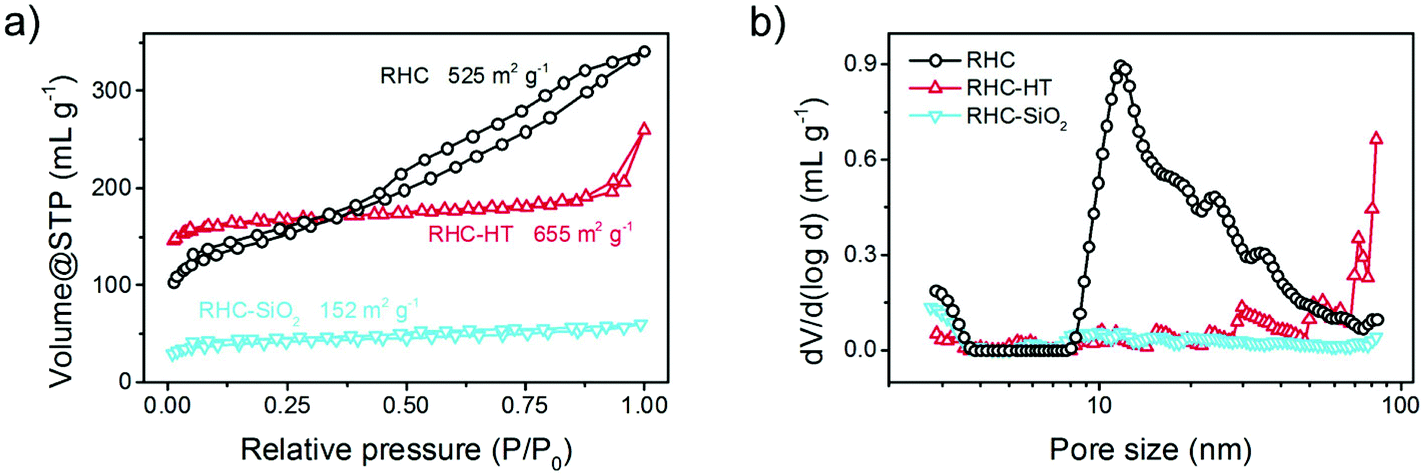 | ||
| Fig. 3 (a) N2 isothermal sorption and (b) corresponding pore size distribution based on density functional theory of RHC-HT, RHC-SiO2, and RHC. | ||
By comparing the isotherms of RHC and RHC-SiO2, we attribute the formation of mesopores in RHC to the removal of SiO2 templates that are inherently derived from silica impurities in the natural RH precursor. Therefore, the additional introduction of expensive artificial templating materials is avoided for our scalable and cost-effective synthesis.
The surface area and pore size distribution are further resolved by the Brunauer–Emmett–Teller (BET) method and quenched solid density functional theory (QSDFT), respectively. The specific surface area of RHC-HT, RHC-SiO2, and RHC is 655, 152, and 525 m2 g−1, respectively, indicating the great contribution of micropores to the surface exposure; while the mesopores mainly dominate the overall pore volume (Fig. 3b). Among the three samples, RHC has the highest mesopore volume and adequate micropores. The detailed pore volume and fraction of each pore category is summarized in Table 1. Generally, the micropores are resulted from the rapid volatilization of light organics and amorphization of carbonaceous segments during direct carbonisation at a relatively high temperature of 900 °C, which is enhanced by the pre-treatment under hydrothermal conditions, whereas the mesopores are mainly derived from the replication of in situ formed silica templates. The unique structural feature of the RH precursor is that silica crystallites are uniformly embedded and wrapped by natural carbon precursors including cellulose, hemicellulose, and lignin affording thus a desirable template/precursor mixture for efficient synthesis of hierarchical porous carbon via a simple approach. The resultant pore hierarchy is believed to play a key role in the electrochemical performance in terms of the charge/mass transport.
| Sample | BETa | QSDFTb | ||||
|---|---|---|---|---|---|---|
| Pore volume (cm3 g−1) | Fraction of SSA (%) | Fraction of pore volume (%) | ||||
| SSAc (m2 g−1) | Microd | Mesod | Microd | Mesod | ||
| a The specific surface area is calculated based on Brunauer–Emmett–Teller theory. b The cumulative surface area and pore volume of micro-/mesopores are calculated based on quenched solid state density functional theory. c Specific surface area is abbreviated as SSA in this table. d Micropore is defined as the pore with a pore width less than 2 nm while the mesopore has a pore width larger than 2 nm. | ||||||
| RHC | 525 | 0.488 | 59.9 | 40.1 | 23.6 | 76.4 |
| RHC-HT | 655 | 0.315 | 95.9 | 4.1 | 72.7 | 27.3 |
| RHC-SiO2 | 152 | 0.083 | 83.5 | 16.5 | 59.0 | 41.0 |
We have prepared rice husk derived carbon/sulphur (C/S) composites via a typical melting-diffusion method. As indicated in a typical TEM image of RHC/S composites, sulphur was uniformly coated on the carbon surface and impregnated in the porous structure (Fig. 4).
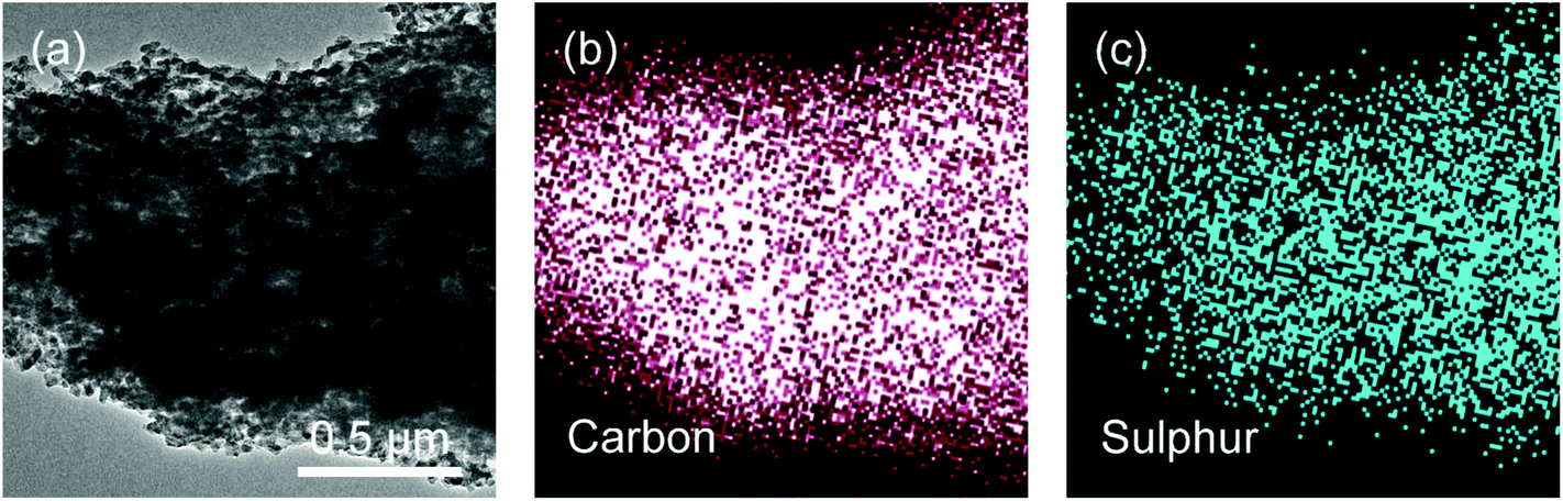 | ||
| Fig. 4 (a) TEM image and corresponding EDS mapping of (b) carbon and (c) sulphur of 56% RHC/S. | ||
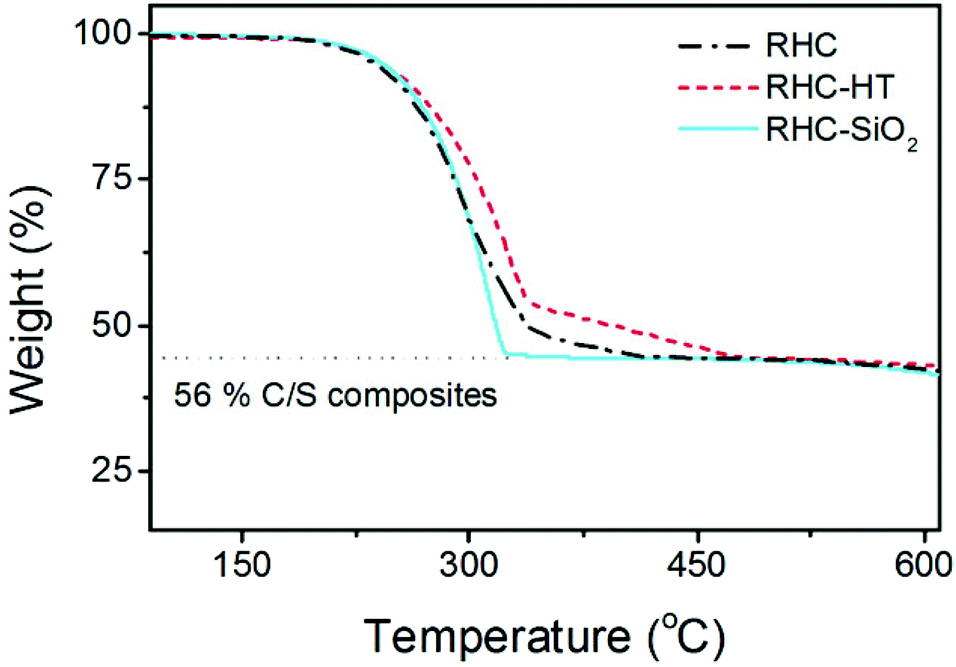
The thermal properties of sulphur in each C/S composite vary with the porous structure (Fig. 5). All the three C/S composites exhibit similar sulphur weight content of around 56%.
 | ||
| Fig. 5 Thermogravimetric (TG) analysis on C/S composites of RHC-HT, RHC-SiO2, and RHC. | ||
However, the weight loss of sulphur varies depending on the porosity of the carbon matrix. Both RHC-HT/S and RHC/S share a similar TG curve of sulphur, with a rapid weight loss between 220 and 340 °C which then declines gradually within a temperature interval of 340–480 °C. It was demonstrated that sulphur confined in the micropores has a better thermal stability under an inert atmosphere compared to sulphur confined within the mesopores. Therefore, the prolonged weight loss of RHC-HT/S suggests that a part of sulphur is well impregnated into the micropores especially considering that this material has the highest volume of micropores (0.229 cm3 g−1) among all samples.
On the contrary, RHC-SiO2/S displays features that suggest that sulphur is stored in the large macro/mesopores as a result of small micropore volume (0.049 cm3 g−1). It can be deduced that RHC-HT/S has the best sulphur storage due to the dominant microporous texture of RHC-HT.
Li–S cells were assembled to evaluate the electrochemical performance of rice husk derived carbon materials by pairing a C/S composite cathode and a lithium counter electrode. 1.0% weight of LiNO3 was added in the electrolyte to passivate the lithium anode. For a parallel comparison and demonstration of the intrinsic properties of biomass derived carbon, a relatively low sulphur loading amount of 1.0 mg cm−2 was adopted.
As shown in Fig. 6a, the C/S composite cathodes of RHC, RHC-HT, and RHC-SiO2 exhibit initial capacities of 834, 697, and 563 mA h g−1, respectively at a current density of 0.5 C (1C = 1672 mA g−1). After 500 cycles, RHC/S has a capacity of around 600 mA h g−1 while the capacities of RHC-HT/S and RHC-SiO2/S are less than 500 mA h g−1. Note that there is an activation procedure for the RHC-HT/S composite to reach the maximum capacity of 764 mA h g−1 during the initial 10 cycles.
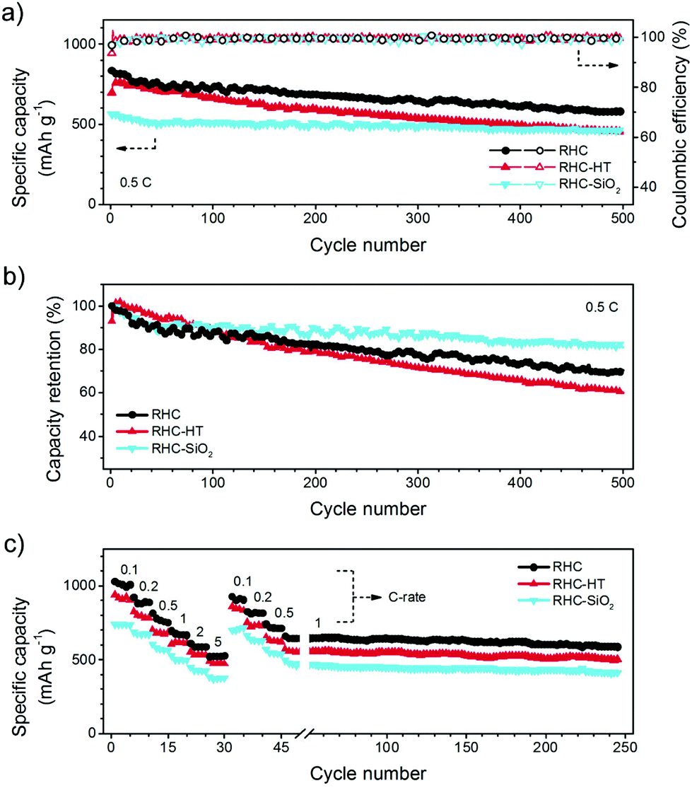 | ||
| Fig. 6 Li–S battery performance of RHC-HT, RHC-SiO2, and RHC: (a) cycling performance and (b) corresponding capacity retention at a current density of 0.5 C (1C = 1672 mA h g−1). The open and solid dots in (a) indicate the charge and discharge capacity, respectively. (c) Rate performance. After the rate test, there is a long-term cycling at the current density of 1.0 C. | ||
We calculated the capacity retention with respect to the maximum capacity (Fig. 6b). The capacity retention of the C/S composite cathodes of RHC, RHC-HT, and RHC-SiO2 is 70, 60, and 81%, respectively. The enhanced capacity retention of RHC-SiO2 is ascribed to the hydrophilicity of SiO2 particles embedded in the carbon framework. According to the first-principles calculations based on density functional theory, there is a binding energy of 1.22 eV between Li2S4 and the (110) plane of SiO2 with oxygen-terminated surface (Fig. S2‡), which is much larger than 0.34 eV (ref. 32) between Li2S4 and graphene. The introduction of SiO2 facilitates the trapping capability to polar intermediate polysulphides via polar–polar interactions, which is similar to the use of oxides33 and heteroatoms34,35 to anchor the intermediates and final products.
The best lithium storage performance of RHC/S composites has been validated by the rate performance as well (Fig. 6c). A high capacity of 1032 mA h g−1 is achieved for RHC/S at a current density of 0.1 C and can be maintained above 500 mA h g−1 at a high current rate of 5.0 C. Even after cycled at 1.0 C for 200 cycles, a capacity of 586 mA h g−1 is well sustained, manifesting a fascinating cyclic decay rate of 0.055%. In contrast, the rate capability of RHC-HT/S and RHC-SiO2/S is inferior to RHC/S.
Other natural resources have been strongly considered as carbon precursors for advanced Li–S batteries. For instance, bamboo,36 leaf,37 eggshell membranes,38 and cassava39 were explored as carbon precursors to serve as entrapping agents to absorb the polysulphide intermediates. Some other biomass-derived carbon materials, including crab shell,17 pig bone,18 fish scale,19 kapok fiber,20 pomelo peel,35 fungi,22 and plane-tree bark,23 have been considered as conductive scaffolds for Li–S batteries. As shown in Table 2, the current rice husk derived carbon exhibited comparative sulphur utilization with that from crab shell,17 pig bone,18 pomelo peel,35 fungi,22 and plane-tree bark.23 An outstanding stability corresponding to the small decay rate of rice husk derived carbon of ca. 0.055% per cycle is achieved, which is much smaller than the value of 0.22–1.0% per cycle on other biomass derived carbon scaffolds.17–20,22,23,35
| Carbon | SSA (m2 g−1) | Sulphur loading (mg cm−2) | Discharge capacitya (mA h g−1) | Sulphur utilizationb (%) | Decay ratec | Ref. |
|---|---|---|---|---|---|---|
| a If not specified, the discharge capacity is obtained at 0.5 C. b The sulphur unitization is defined as the ratio of discharge capacity at 0.5 C and theoretical value of 1672 mA h g−1. c The discharge capacity decay rate is calculated at a current rate of 0.5 C if it is not specified. Its unit is ‘% per cycle’. d The current density is 0.4 A g−1. e The current density is 1.0 C. f The current density is 0.1 A g−1. g The current density is 0.2 A g−1. h CNT refers to carbon nanotube. | ||||||
| Biomass derived carbon | ||||||
| Hollow fiber from crab shell | — | 0.8 | 786 | 47 | 0.18 | 17 |
| Porous carbon from pig bone | 2157 | — | 1265d | 76 | 0.98d | 18 |
| Carbon from fish scales | 2441 | 0.8–1.0 | 980e | 59 | 0.55e | 19 |
| Nanotiles from kapok fibers | 282 | — | 870f | 52 | — | 20 |
| Foam from pomelo peel | 1533 | 1.76 | 1258 | 75 | 0.4 | 21 |
| Fiber monolith from fungi | 305 | — | 810 | 48 | 0.38 | 22 |
| Carbon from plane-tree bark | 528 | 1 | 1159g | 69 | 0.79g | 23 |
| Graphene and CNT | ||||||
| Fibrous graphene | — | 2 | 710 | 42 | 0.24 | 13 |
| One-pot graphene/CNT | 73 | 1.2 | 946 | 56 | 0.26 | 41 |
| RHC-HT | 655 | 1.0 | 697 | 42 | 0.080 | This work |
| RHC-SiO2 | 152 | 1.0 | 564 | 34 | 0.055 | |
| RHC | 525 | 1.0 | 834 | 50 | 0.060 | |
| RHC | 525 | 2.1 | 1042d | 62 | 0.15d | |
The use of rice husks derived carbons in Li–S batteries illustrated the following interesting features: (1) the inherent empty space accommodates the active sulphur, as well as the volume expansion of sulphur to lithium sulphides during discharge process; (2) the very high area of inner surface is important for depositing active sulphur containing species with interlinked electron pathways in a working cell; (3) the interconnected micro-/mesopores served as diffusion channels for facile Li+ diffusion; (4) the polarized surface contributed from the oxygen-containing functional groups13 or oxide33 can anchor polysulphides, which is a facile chemical route to absorb intermediates and maintain a cell with a very long cycle life; (5) the rice husk template is mainly composed of SiO2, which can be facilely removed using dilute HF solution; (6) the huge abundant resources of rice husks afford reliable precursors for robust fabrication of the RHC related sample, which can meet the potential practical applications of Li–S batteries with bulk requirement on carbon scaffolds.
We further probed the role of the porous hierarchy for sulphur accommodation and utilization for Li–S batteries. Herein, it is interesting to notice that the RHC-HT/S composite, the one possessing the best accommodation of sulphur as indicated by TG results, has an inferior electrochemical performance compared with the RHC/S composite, in which the carbon host has a hierarchical micro-/mesopore system. In most cases, the sulphur confined in the micropores has the highest stability against dissolution and shuttling though the applied sulphur content is relatively low (<42%).40 To probe the role of micropores and mesopores in our RH-derived hierarchical porous carbon, we meticulously examined the galvanostatic discharge/charge behaviour of each C/S composite (Fig. 7).
 | ||
| Fig. 7 (a) Galvanostatic charge–discharge profiles of RHC-HT, RHC-SiO2, and RHC at current density of 0.5 C. Capacity retention of different voltage plateaus of RHC-HT, RHC-SiO2, and RHC: (b) high plateau (2.3–2.4 V, Qhigh) and (c) low plateau (2.0–2.1 V, Qlow). | ||
All samples exhibit the typical discharge–charge curves of Li–S batteries. The most common feature is the two-plateau discharge curve, in which the high plateau around 2.3–2.4 V (denoted as Qhigh) corresponds to the conversion of sulphur to soluble polysulphides (Li2Sx, x = 4–8) whereas the low plateau around 2.0–2.1 V (denoted as Qlow) indicated the transformation from Li2Sx to solid compounds of Li2S2/Li2S.
However, the capacity provided by Qhigh or Qlow varies significantly from each sample. For comparison, the capacity contribution of Qhigh and Qlow is plotted in Fig. 7b and c. It is obvious that the intimate contact between sulphur and carbon in pristine RHC-HT/S composites renders a high initial capacity of Qhigh. However, as a result, despite the microporous feature of RHC-HT, its mesopore volume is small and incapable of providing sufficient space neither for solid Li2S growth/deposition nor for rapid ion transport, thereby leading to relatively small initial capacity of Qlow. For the same reason ion diffusion is limited by the narrow and tortuous channels of micropores. Therefore around 5 cycles are required to activate the sulphur accommodation in the inner micropores. Initially sulphur is unavailable to contact the electrolyte. Similarly, around 20 cycles are required to maximize the Qlow. The subsequent decrease of capacities at rapid cyclic decay rates for both Qhigh (0.16%) and Qlow (0.11%) during 200 cycles is ascribed to the insufficient mesopores of RHC-HT volume for solid deposition. The accumulation of solid products within the micropores or around the entrance of micropores is believed to block the ion diffusion from bulk electrolytes into the inner micropores and to retard the accessibility of soluble polysulphides to the conductive surface.
On the contrary, RHC has more mesopore volume when compared to RHC-HT. Although RHC/S exhibits relatively smaller capacity Qlow due to the lower overall surface compared with RHC-HT, the sufficient mesopore volume allows efficient deposition of solid products, leading to much lower cyclic decay rates for both Qhigh (0.09%) and Qlow (0.09%). Actually, the Qlow of RHC/S is nearly stabilized after 20 cycles, which is different to the RHC-HT/S material with a constant decay of Qlow, further indicating the key role of mesopores in cycling stability of Li–S batteries. Considering the large volume expansion of sulphur during lithiation, the macropores presented in the RHC, in addition to mesopores, also contribute to the enhanced buffering effect by providing sufficient space.
It is also interesting to find that RHC-SiO2, which can be almost regarded as a non-porous carbon when compared to RHC or RHC-HT, displays the best capacity retention of Qlow and a moderate retention of Qhigh regardless of their low absolute value. The non-porous carbon is generally accepted to provide a very limited effect on immobilizing polysulphides. The discrepancy between the results of RHC-SiO2/S and conventional understanding prompts rethinking of the confining effect of porous substrates on polysulphides. At least we know that the confinement should not be overestimated at the cost of ion transportation as well as the deposition space for S/Li2S unless sulphur can be accommodated in the form of short-chain S2–S4 under extraordinary geometric confinement of ultrasmall micropores (<0.5 nm) and coupled with polysulphide-insoluble carbonate electrolytes.40 However, it is also commonly accepted that synthesis of ultramicroporous carbon with a large pore volume for commercially viable sulphur content (>70%) is extremely challenging. Note that SiO2 components in RHC-SiO2 may have a positive impact on adsorbing polar polysulphides.33
Cyclic voltammetry (CV) and electrochemical impedance spectroscopy (EIS) were also conducted to further validate the role of mesopores (Fig. 8). As shown in Fig. 8a, sulphur cathodes based on RHC and RHC-SiO2 both exhibited two cathodic peaks and one anodic peak, which are in good accordance with the galvanostatic discharge–charge curves and the corresponding Li–S mechanism. However, the polarization of RHC is much lower than that of RHC-SiO2 because of the better penetration of electrolyte and ion transport in mesopore-rich RHC. RHC-HT/S exhibited a delayed cathodic peak at around 1.75 V, which implies slow transport of ions in the narrow micropores. Similarly, EIS of RHC/S indicated the smallest charge-transfer resistance while the RHC-HT/S and RHC-SiO2/S displayed roughly 100% and 250% higher than that of RHC/S, respectively (Fig. 8b). Therefore, the adequate mesopores in RHC also result in better electrochemical kinetics.
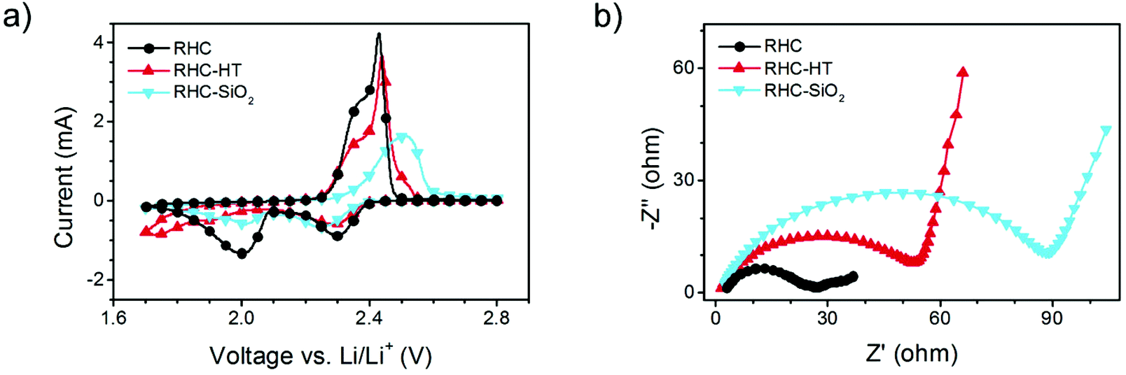 | ||
| Fig. 8 (a) CV curves and (b) EIS of RHC-HT, RHC-SiO2, and RHC. | ||
C/S composite cathodes after cycling were characterized by SEM (Fig. 9). Cycled RHC/S still exhibited a highly porous morphology, where the carbon and sulphur elements distributed uniformly (Fig. 9a). RHC-SiO2/S showed a similar morphology, but there were substantial vacancies left (Fig. 9b). One possible reason for these vacancies is that sulphur coated on the outer surface dissolved in the electrolyte. Such a dissolution of unrestricted sulphur accounts for the low overall capacity of RHC-SiO2/S. Even though the embedded SiO2 has favourable polar surface to enhance the capacity retention, the limited pore volume prevented the chemisorption of most of the soluble intermediates, thus leading to stable cycling at relatively low capacity. In the cycled RHC-HT/S, sulphur was found mostly coated on the outer surface (Fig. 9c), further suggesting that micropores with small pore volume are incapable of trapping a great amount of active materials. Instead, the ion transport might be impeded.
 | ||
| Fig. 9 SEM images and corresponding EDS mapping of carbon and sulphur of cycled C/S electrodes: (a) RHC, (b) RHC-SiO2, and (c) RHC-HT. | ||
The hierarchical porous carbon materials with desirable and adequate hydrophilic/amphiphilic decorations would be promising candidates for future upgrading. For example, RHC with partially removed SiO2 templates might be promising if we still intended to exert the advantages of our synthetic routes from abundant RH resources in terms of the cost, simplicity, and scalability.
The importance of sufficient mesopore volume as ion channels and reaction chambers is further verified by Li–S batteries with high sulphur loading amount. 75% C/S composite of RHC was prepared, where sulphur was still distributed uniformly in the carbon structure (Fig. 10). However, 75% RHC/S composite has more mesopores filled by sulphur and therefore less available mesopores for buffering ions (Fig. 11a). As a result, the 75% RHC/S performs much worse in terms of cycling stability than the 56% RHC/S even though the sulphur loading amount of 56% RHC/S (2.1 mgS cm−2) is ∼31% higher than 75% RHC/S (1.6 mgS cm−2). Nevertheless, the sulphur still distributed well in the 75% RHC/S composite (Fig. 10).
 | ||
| Fig. 10 (a) TEM image and corresponding EDS mapping of (b) carbon and (c) sulphur of 75% RHC/S. | ||
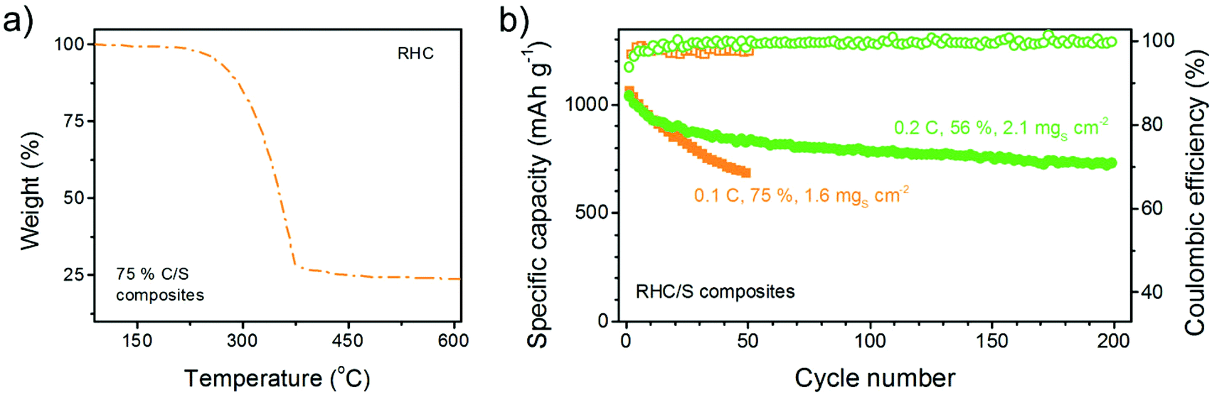 | ||
| Fig. 11 (a) TG curve of 75% C/S composites and (b) cycling performance of high-sulphur-loading batteries with 56% RHC/S composites at 2.1 mgS cm−2 or 75% RHC/S composites at 1.6 mgS cm−2. | ||
It is well accepted that both an increase in the sulphur weight content or areal loading amount can decrease the stability of C/S composites. However, in our case, even if the absolute current density of 56% RHC/S (0.70 mA cm−2) is 2.6 times that of the 75% RHC/S (0.27 mA cm−2), the 56% RHC/S exhibits a comparable initial capacity (1042 mA h g−1) to, but a much better cycling stability (0.15% cyclic decay) than, 75% RHC/S (1065 mA h g−1 and 0.72% cyclic decay) (Fig. 11b).
Therefore, the good maintenance of adequate mesopores for ion transfer is of considerable significance especially for the stable operation of high-sulphur-loading Li–S batteries that favours overall specific energy of the whole cell for practical applications.
3. Conclusion
We facilely fabricated a series of carbon material with hierarchical micro-/mesopores from natural rice husk and have investigated the relationship between porosity hierarchy and the Li–S performance. The rice husk comprises dominantly of natural carbon sources such as cellulose/hemicellulose/lignin with uniformly embedded silica crystallites which provides a desirable template/precursor mixture for efficient synthesis of hierarchical porous carbon via a simple approach. Hydrothermal carbonisation is beneficial for the formation of micropores and their narrow distribution, while high temperature carbonisation is effective to obtain mesopores after SiO2 removal. When used as the cathode scaffold for Li–S batteries, a high capacity of 1032 mA h g−1 was achieved for RHC/S at a current density of 0.1 C which can be maintained above 500 mA h g−1 at a high current rate of 5 C. Importantly, it was demonstrated that the appearance of abundant micropores with higher surface area rendered a high initial capacity of Qhigh, however, the sufficient mesopore volume was more vital for a lower cyclic decay, which was prerequisite for the generation of solid products and smooth ion diffusion. Additionally, the SiO2 particles embedded in the carbon framework were revealed to enhance the capacity retention, which was ascribed to the excellent trapping capability to polar intermediate polysulphides via polar–polar interactions. Thereby, the hierarchical porous carbon materials with adequate micropores and mesopores, together with desirable hydrophilic/amphiphilic decorations would be promising candidates for future upgrading towards promising Li–S batteries. This work sheds novel light on the structural features towards effective cathode materials for high-performance Li–S batteries, which is believed to be instructive for further development in this field and analogous material or sustainable energy systems.4. Experimental section
Materials
The rice husk was sourced from a local farmer in Ibaraki Prefecture, Japan; ammonium hydrogen difluoride was purchased from Sigma Aldrich. All reagents were used without further purification.Methods and apparatus
The rice husk was ground to a maximum size of 0.8 mm. Typically, 2.0 g of the rice husk powder was placed in a glass inlet (30 mL volume) sealed in a 50 mL Teflon autoclave and maintained at a temperature of 230 °C for 48.0 hours. Then, the autoclave was cooled down, and the carbon powder was washed and dried at 80 °C for 10.0 h. The black powder was finally carbonized under an inert Ar atmosphere, involving material heating to a temperature of 900 °C with a ramping rate of 5 °C min−1. Afterwards, the samples were soaked in 4.0 M NH4HF2 [RHC-HT] in order to remove the SiO2. The materials were washed with distilled water until the pH of the filtrate was neutral. The same procedure was followed for the sample without an HTC approach by direct carbonisation of rice husk. The samples were named RHC-SiO2 and RHC in the case of the same without silica.The infiltration of S into the carbon samples was through a melt-diffusion process at 155 °C under vacuum for 6.0 h. The electrode slurry contained 80% of C/S composites, 10% of carbon nanotubes as conductive agents, and 10% of PVDF binder. Two-electrode cells using 2025 coil-type cells were constructed to study the electrochemical performance of the C/S cathode for Li–S batteries. The electrolyte was 1.0 M lithium bis-(trifluoromethanesulfonyl)imide solution – 1,3-dioxolane/1,2-dimethoxyethane containing 1.0 wt% LiNO3. The areal loading amount of sulphur is ranging from 1.0 to 2.1 mg cm−2.
The samples were characterised by scanning electron microscopy (SEM, FEI Quanta 3D) and transmission electron microscopy (JOEL JEM 2010). Thermal responses of the carbon samples were recorded by thermal gravimetric analysis (TGA) using a NETZSCH TG 209F3 TGA209F3A-0346-L thermal analyzer. The Raman spectra were recorded on the Raman Scattering Spectroscopy (Renishaw 2000 system) with excitation by a diode laser (632 nm, laser power of 25 mW) in backscattering geometry. XRD patterns were recorded with a Siemens D5000 X-Ray powder diffractometer with Cu Kα radiation. Each pattern was recorded with a step size of 0.03°. Quantachrome NovaWin Version 11.03 was assigned to measure the total surface area. The sulphur ratios of C/S composites were determined by routine TGA through a Mettler-Toledo TGA/DSC1 STARe system under a N2 flow. The N2 sorption isotherms of the carbon materials were recorded on a Quantachrome Instrument Autosorb-IQ2-MP-C system. The surface area and pore size distribution were further resolved by the Brunauer–Emmett–Teller (BET) method and nonlocal density functional theory, respectively.
Acknowledgements
This work was supported by the Natural Scientific Foundation of China (No. 21422604 and 21561130151) and National Basic Research Program of China (2015CB932500). Q. Z. and M. M. T. acknowledged the support of Newton Advanced Fellowship (No. NA140249) from the Royal Society, UK. We thank Mr Xiang Chen and Ting-Zheng Hou at Tsinghua University for theoretical calculation. M. K. Rybarczyk acknowledged the financial support for scientific stay at QMUL – UK within the project directed by Prof. Maciej Baginski: “The development of interdisciplinary doctoral studies at the Gdansk University of Technology in modern technologies – Project No. POKL.04.01.01-00-368/09”.References
- S. Gadipelli and Z. X. Guo, ChemSusChem, 2015, 8, 2123 CrossRef CAS PubMed.
- K. V. Kumar and F. Rodriguez-Reinoso, RSC Adv., 2012, 2, 9671 RSC.
- M. K. Rybarczyk, M. Lieder and M. Jablonska, RSC Adv., 2015, 5, 44969 RSC.
- T. P. Fellinger, A. Thomas, J. Y. Yuan and M. Antonietti, Adv. Mater., 2013, 25, 5838 CrossRef CAS PubMed; A. Lisowska-Oleksiak, A. P. Nowak and B. Wicikowska, RSC Adv., 2014, 4, 40439 RSC.
- G. M. Zhou, Y. B. Zhao and A. Manthiram, Adv. Energy Mater., 2015, 5, 1402263 Search PubMed.
- Z. Li, Y. M. Huang, L. X. Yuan, Z. X. Hao and Y. H. Huang, Carbon, 2015, 92, 41 CrossRef CAS; G. M. Zhou, L. Li, D. W. Wang, X. Y. Shan, S. F. Pei, F. Li and H. M. Cheng, Adv. Mater., 2015, 27, 641 CrossRef PubMed; J. Liang, Z.-H. Sun, F. Li and H.-M. Cheng, Energy Storage Mater., 2016, 2, 76 CrossRef.
- S. Evers and L. F. Nazar, Acc. Chem. Res., 2013, 46, 1135 CrossRef CAS PubMed; A. Manthiram, S. H. Chung and C. X. Zu, Adv. Mater., 2015, 27, 1980 CrossRef PubMed; J.-Q. Huang, Q. Zhang and F. Wei, Energy Storage Mater., 2015, 1, 127 CrossRef; X. Fang and H. S. Peng, Small, 2015, 11, 1488 CrossRef PubMed.
- R. J. Chen, T. Zhao and F. Wu, Chem. Commun., 2015, 51, 18 RSC; L. Ma, K. E. Hendrickson, S. Y. Wei and L. A. Archer, Nano Today, 2015, 10, 315 CrossRef CAS.
- C. D. Liang, N. J. Dudney and J. Y. Howe, Chem. Mater., 2009, 21, 4724 CrossRef CAS.
- G. He, X. L. Ji and L. Nazar, Energy Environ. Sci., 2011, 4, 2878 CAS.
- J. T. Lee, Y. Y. Zhao, S. Thieme, H. Kim, M. Oschatz, L. Borchardt, A. Magasinski, W. I. Cho, S. Kaskel and G. Yushin, Adv. Mater., 2013, 25, 4573 CrossRef CAS PubMed.
- Z. Li, Y. Jiang, L. X. Yuan, Z. Q. Yi, C. Wu, Y. Liu, P. Strasser and Y. H. Huang, ACS Nano, 2014, 8, 9295 CrossRef CAS PubMed.
- G. M. Zhou, L. C. Yin, D. W. Wang, L. Li, S. F. Pei, I. R. Gentle, F. Li and H. M. Cheng, ACS Nano, 2013, 7, 5367 CrossRef CAS PubMed.
- M.-Q. Zhao, Q. Zhang, J.-Q. Huang, G.-L. Tian, J.-Q. Nie, H.-J. Peng and F. Wei, Nat. Commun., 2014, 5, 3410 Search PubMed; C. T. Zhao, C. Yu, M. D. Zhang, J. Yang, S. H. Liu, M. Y. Li, X. T. Han, Y. F. Dong and J. S. Qiu, J. Mater. Chem. A, 2015, 3, 21842 Search PubMed; X. B. Cheng, H. J. Peng, J. Q. Huang, R. Zhang, C. Z. Zhao and Q. Zhang, ACS Nano, 2015, 9, 6373 CrossRef CAS PubMed; J. L. Shi, C. Tang, H. J. Peng, L. Zhu, X. B. Cheng, J. Q. Huang, W. C. Zhu and Q. Zhang, Small, 2015, 11, 5243 CrossRef PubMed.
- X. Yang, L. Zhang, F. Zhang, Y. Huang and Y. Chen, ACS Nano, 2014, 8, 5208 CrossRef CAS PubMed; X. A. Chen, Z. Xiao, X. Ning, Z. Liu, Z. Yang, C. Zou, S. Wang, X. Chen, Y. Chen and S. Huang, Adv. Energy Mater., 2014, 4, 1301988 Search PubMed; H.-J. Peng, J.-Q. Huang, M.-Q. Zhao, Q. Zhang, X.-B. Cheng, X.-Y. Liu, W.-Z. Qian and F. Wei, Adv. Funct. Mater., 2014, 24, 2772 CrossRef.
- H. J. Peng, J. Y. Liang, L. Zhu, J. Q. Huang, X. B. Cheng, X. F. Guo, W. P. Ding, W. C. Zhu and Q. Zhang, ACS Nano, 2014, 8, 11280 CrossRef CAS PubMed; Y. Zhao, W. L. Wu, J. X. Li, Z. C. Xu and L. H. Guan, Adv. Mater., 2014, 26, 5113 CrossRef PubMed; C. Tang, B.-Q. Li, Q. Zhang, L. Zhu, H.-F. Wang, J.-L. Shi and F. Wei, Adv. Funct. Mater., 2016, 26, 577 CrossRef; F. Pei, T. An, J. Zang, X. Zhao, X. Fang, M. Zheng, Q. Dong and N. Zheng, Adv. Energy Mater., 2016, 6 Search PubMed.
- H. B. Yao, G. Y. Zheng, W. Y. Li, M. T. McDowell, Z. W. Seh, N. A. Liu, Z. D. Lu and Y. Cui, Nano Lett., 2013, 13, 3385 CrossRef CAS PubMed.
- S. C. Wei, H. Zhang, Y. Q. Huang, W. K. Wang, Y. Z. Xia and Z. B. Yu, Energy Environ. Sci., 2011, 4, 736 CAS.
- S. R. Zhao, C. M. Li, W. K. Wang, H. Zhang, M. Y. Gao, X. Xiong, A. B. Wang, K. G. Yuan, Y. Q. Huang and F. Wang, J. Mater. Chem. A, 2013, 1, 3334 CAS.
- X. Y. Tao, J. T. Zhang, Y. Xia, H. Huang, J. Du, H. Xiao, W. K. Zhang and Y. P. Gan, J. Mater. Chem. A, 2014, 2, 2290 CAS.
- J. Zhang, J. Y. Xiang, Z. M. Dong, Y. Liu, Y. S. Wu, C. M. Xu and G. H. Du, Electrochim. Acta, 2014, 116, 146 CrossRef CAS.
- L. Y. Zhang, Y. Y. Wang, B. Peng, W. T. Yu, H. Y. Wang, T. Wang, B. W. Deng, L. Y. Chai, K. Zhang and J. X. Wang, Green Chem., 2014, 16, 3926 RSC.
- J. Xu, K. Zhou, F. Chen, W. Chen, X. Wei, X.-W. Liu and J. Liu, ACS Sustainable Chem. Eng., 2016, 4, 666 CrossRef CAS.
- M. M. Titirici, R. J. White, N. Brun, V. L. Budarin, D. S. Su, F. del Monte, J. H. Clark and M. J. MacLachlan, Chem. Soc. Rev., 2015, 44, 250 RSC; N. Brun, K. Sakaushi, J. Eckert and M. M. Titirici, ACS Sustainable Chem. Eng., 2014, 2, 126 CrossRef CAS; L. H. Yu, N. Brun, K. Sakaushi, J. Eckert and M. M. Titirici, Carbon, 2013, 61, 245 CrossRef; N. Brun, K. Sakaushi, L. H. Yu, L. Giebeler, J. Eckert and M. M. Titirici, Phys. Chem. Chem. Phys., 2013, 15, 6080 RSC.
- R. Pode, Renewable Sustainable Energy Rev., 2016, 53, 1468 CrossRef.
- C. Real, M. D. Alcala and J. M. Criado, J. Am. Ceram. Soc., 1996, 79, 2012 CrossRef CAS.
- N. Yalcin and V. Sevinc, Carbon, 2000, 38, 1943 CrossRef CAS.
- L. P. Wang, Z. Schnepp and M. M. Titirici, J. Mater. Chem. A, 2013, 1, 5269 CAS.
- S. A. Wohlgemuth, F. Vilela, M. M. Titirici and M. Antonietti, Green Chem., 2012, 14, 741 RSC.
- C. Falco, N. Baccile and M. M. Titirici, Green Chem., 2011, 13, 3273 RSC; C. Falco, F. P. Caballero, F. Babonneau, C. Gervais, G. Laurent, M. M. Titirici and N. Baccile, Langmuir, 2011, 27, 14460 CrossRef CAS PubMed.
- A. C. Ferrari, Solid State Commun., 2007, 143, 47 CrossRef CAS.
- Z. Yuan, H. J. Peng, T. Z. Hou, J. Q. Huang, C. M. Chen, D. W. Wang, X. B. Cheng, F. Wei and Q. Zhang, Nano Lett., 2016, 16, 519 CrossRef CAS PubMed.
- K. T. Lee, R. Black, T. Yim, X. L. Ji and L. F. Nazar, Adv. Energy Mater., 2012, 2, 1490 CrossRef CAS.
- K. Han, J. M. Shen, S. Q. Hao, H. Q. Ye, C. Wolverton, M. C. Kung and H. H. Kung, ChemSusChem, 2014, 7, 2545 CrossRef CAS PubMed; Q. Pang, J. T. Tang, H. Huang, X. Liang, C. Hart, K. C. Tam and L. F. Nazar, Adv. Mater., 2015, 27, 6021 CrossRef PubMed; X. Zhao, Y. Liu, J. Manuel, G. S. Chauhan, H. J. Ahn, K. W. Kim, K. K. Cho and J. H. Ahn, ChemSusChem, 2015, 8, 3234 CrossRef PubMed.
- H. J. Peng, T. Z. Hou, Q. Zhang, J. Q. Huang, X. B. Cheng, M. Q. Guo, Z. Yuan, L. Y. He and F. Wei, Adv. Mater. Interfaces, 2014, 1, 1400227 Search PubMed.
- G. Zhou, Y. Zhao and A. Manthiram, Adv. Energy Mater., 2015, 5, 1402263 Search PubMed.
- S. H. Chung and A. Manthiram, ChemSusChem, 2014, 7, 1655 CrossRef CAS PubMed.
- S. H. Chung and A. Manthiram, Adv. Mater., 2014, 26, 1360 CrossRef CAS PubMed.
- F. R. Qin, K. Zhang, J. Fang, Y. Q. Lai, Q. Li, Z. A. Zhang and J. Li, New J. Chem., 2014, 38, 4549 RSC.
- S. Xin, L. Gu, N. H. Zhao, Y. X. Yin, L. J. Zhou, Y. G. Guo and L. J. Wan, J. Am. Chem. Soc., 2012, 134, 18510 CrossRef CAS PubMed.
- S. Z. Niu, W. Lv, C. Zhang, Y. T. Shi, J. F. Zhao, B. H. Li, Q. H. Yang and F. Y. Kang, J. Power Sources, 2015, 295, 182 CrossRef CAS.
Footnotes |
| † Dedicated to Professor James Clark on occasion of his 65th birthday. |
| ‡ Electronic supplementary information (ESI) available. See DOI: 10.1039/c6gc00612d |
| § These authors contributed equally to this work. |
| This journal is © The Royal Society of Chemistry 2016 |