Highly conductive and durable poly(arylene ether sulfone) anion exchange membrane with end-group cross-linking†
Kang Hyuck
Lee
a,
Doo Hee
Cho
 a,
Young Mi
Kim
a,
Sun Ju
Moon
a,
Jong Geun
Seong
a,
Dong Won
Shin
ab,
Joon-Yong
Sohn
ac,
Jeong F.
Kim
a and
Young Moo
Lee
a,
Young Mi
Kim
a,
Sun Ju
Moon
a,
Jong Geun
Seong
a,
Dong Won
Shin
ab,
Joon-Yong
Sohn
ac,
Jeong F.
Kim
a and
Young Moo
Lee
 *a
*a
aDepartment of Energy Engineering, College of Engineering, Hanyang University, Seoul 04763, Republic of Korea. E-mail: ymlee@hanyang.ac.kr
bFuel Cell Laboratory, Korea Institute of Energy Research, Daejeon 34129, Republic of Korea
cDepartment of Energy Radiation Research Division for Industry and Environment, Advanced Radiation Technology Institute, Korea Atomic Energy Research Institute, 1266 Sinjeongdong, Jeongeup-si, Jeollabuk-do 56212, Republic of Korea
First published on 2nd December 2016
Abstract
Here, we demonstrate the improved electrochemical performance and stability of end-group cross-linked anion exchange membranes (AEM) for the first time via the introduction of imidazolium groups in poly(arylene ether sulfone) (Imd-PAES). A novel feature of the cross-linking reaction is that basic additives are not required to prevent gelation with the cationic functional groups. In this work, the sodium salt of 3-hydroxyphenylacetylene acted directly as the end-group cross-linker, and it was cross-linked by thermal treatment at 180 °C. The gel fraction and hydroxide conductivity of the cross-linked membranes (XE-Imds) depended on the cross-linking temperature and time. The prepared XE-Imd70 (70 refers to the degree of functionalization) membranes with an ion exchange capacity (IEC) of 2.2 meq g−1 achieved a high hydroxide conductivity (107 mS cm−1). This material also showed good single cell performance (XE-Imd70: 202 mA cm−2 at 0.6 V and a maximum power density of 196.1 mW cm−2) at 80 °C, 100% relative humidity (RH), and improved durability and alkaline stability. The excellent hydroxide conductivity and electrochemical performance of XE-Imd70 was due to the fact that the ion cluster size of XE-Imd membranes was larger (12.1–14 nm) than that of E-Imd (5.5–8.14 nm), indicating that XE-Imd membranes have a closely associated ion-clustered morphology, which was confirmed by transmission electron microscopy (TEM) and small angle X-ray scattering (SAXS) measurements.
Broader contextAlkaline fuel cells (AFCs) using anion exchange membranes (AEMs) are a potential future clean energy technology. While it is true that AEM research still lags behind research associated with proton exchange membranes (PEMs), AEMs can provide potential advantages such as diversification of catalyst composition, including non-precious metals in place of platinum (Pt), and may result in enhanced oxygen reduction kinetics. Research on new membrane materials is essential to overcome the current drawbacks, which include low alkaline stability and poor durability during operation. Optimization of the membrane morphology and efficient water management through the end-group cross-linking method could be a strategy of addressing these problems. Moreover, membrane properties, such as swelling, hydration number, ionic conductivity and even membrane morphology can be tuned by controlling the cross-linking temperature and time. The durability and chemical resistance can also be dramatically enhanced in addition to potential improvements in conductivity and single cell performance. Such end-group cross-linking strategies with AEM have high potential for use in various applications such as reinforced pore-filling composite AEMs, redox flow batteries, and reverse electrodialysis. |
Introduction
Currently, commercial hydrogen fuel cell vehicles mostly employ perfluorosulfonic acid (PFSA) membranes such as Nafion®, Flemion® and Aquivion® as proton exchange membranes (PEM) despite their disadvantages such as low thermal stability, high fuel cross-over, and high cost.1–3 In addition, PFSAs show a decrease in performance at high temperature (>90 °C) and low relative humidity (e.g., 35% relative humidity (RH)).4,5 In order to overcome these limitations, many researchers have worked on improving the performance of PEM fuel cells (PEMFC) on several fronts including: synthesizing new polymer materials,2,3 modifying the chemical structure,6–10 investigating various surface treatments and developing blends or composite membranes.4,11 However, PFSAs and all PEMs require expensive platinum (Pt) catalysts for effective redox reactions.2Unlike PEMFCs, alkaline fuel cells (AFCs) using anion exchange membranes (AEMs) can employ non-precious metal catalysts without Pt. In particular, AFCs showed enhanced oxygen reduction kinetics at the cathode compared to PEMFCs.3,12,13 However, in AEMs, there is as yet no optimized commercial membrane that shows the electrochemical performance required for AFC. In addition, the membrane stability in an alkaline environment is very important as this stability is required if AEMs are to be used in actual AFC stacks.14–16 Many studies have been conducted to overcome the above challenges.
In the field of polymer chemistry, physical (e.g., ionic) or chemical (e.g., covalent) cross-linking methods are effective ways to achieve high stability and good electrochemical performance.10,17–21 Chemical cross-linking methods have been widely employed to optimize membrane morphology to achieve high conductivity and to improve the physical properties, such as thermal stability, chemical stability or mechanical durability. The overall strategy for cross-linking is the same for both cation exchange membranes (CEMs) and AEMs. In fact, many studies have focused on cross-linking of CEMs during the last decade. Studies focusing on connecting the polymer main chains have been widely conducted using cross-linkers such as dihalides, diols, dithiols, and dicarboxylic acids under basic or catalytic conditions.17,18,22 In these methods, controlling the degree of cross-linking is very important. The degree of cross-linking has to be kept low to avoid unwanted gelation and to allow full solvation in various solvents.
The use of branched monomers is another widely employed chemical cross-linking method. For example, tris-amine, tris-alcohol, tris-halide monomers or hexachlorocyclotriphosphazene have been used for cross-linking or to introduce branched structures.23,24 However, the introduction of such branched monomers for fabrication of polymer electrolyte membranes may not be a suitable option due to the difficulty in obtaining high molecular weights and appropriate solubility. Additionally, some membranes having branched structures exhibited poor mechanical properties due to their three-pronged branch structure.
Diverse cross-liking methods for AEM have also been used to improve performance, durability and stability. Specifically, dialdehyde, diol, dithiol and tetraepoxy groups have been used to cross-link the main polymer chains in a manner similar to the difunctional monomers used in CEMs.3,18,25 For example, 1,4-diazabicyclo(2,2,2)octane (DABCO) was used as a cross-linker between –CH2Cl or –CH2Br groups. The cross-linked DABCO can act as an anion exchanger through the resulting quaternary ammonium salt. However, this method has limitations as it may result in poor solubility or require additional cross-linker monomers.
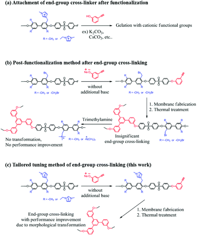
There have been many reports on chemical cross-linking using double or triple-bonds in polymers, mainly via thermal or UV treatment.8,19,20,26–28 Double bonds can be used to form connecting bridges, and triple bonds can be used to for cyclization reactions. For example, thermal ‘click’ reactions using azide groups are a well-known way to form connecting triazole groups.27,29 Such methods offer a flexible means to tune the degree of cross-linking by controlling the temperature, time or UV exposure conditions. In our previous PEM studies, these end-group cross-linking methods resulted in morphological transformations that were used to optimize proton transport8,20,27 and provide efficient water management capability and advanced electrochemical performance.
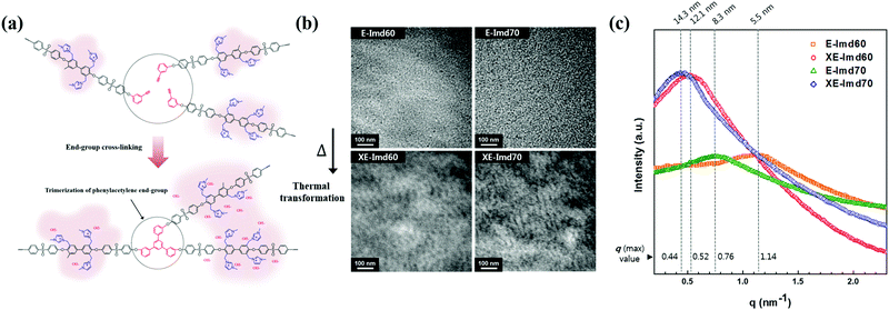
Cross-linking methods by using double or triple bonds have not been performed for AEMs, due to the need for radical bromination or chloromethylation conditions during the synthetic process. Moreover, the cationic functional groups in the final polymer interrupt the basic substitution reaction that is used to introduce monomers having double or triple bonds. In the case of post amine treatment after membrane fabrication with cross-linking, improvements by cross-linking could not be expected. This is because the key point of cross-linking using double or triple bonds is to form a cluster-like morphology of ion exchange functional groups (Scheme 1).
In this study, we introduce a tailored tuning method for AEMs by using triple bonds as polymer end-groups. A novel imidazolium-functionalized end-group cross-linkable copolymer was successfully synthesized. The prepared membranes were thermally cross-linked by end-group alkyne trimerization. The effects of end-group cross-linking and correlations between the degree of cross-linking and membranes properties were investigated in detail. In addition, we determined the optimized cross-linking methods and demonstrated a trade-off relationship between cross-linking time and performance.
Experimental
Materials
Biphenol (BP), N-bromosuccinimide (NBS), benzoyl peroxide (BPO), 1,1,2,2-tetrachloroethane, 1-methylimidazole, 3-hydroxyphenylacetylene, N,N-dimethylacetamide (DMAc), N,N-dimethylformamide (DMF), 1-methyl-2-pyrrolidinone (NMP), potassium carbonate (K2CO3), sodium hydroxide (NaOH), sodium iodide (NaI), sodium chloride (NaCl), sodium sulfate (Na2SO4), silver nitrate (AgNO3), potassium chromate (K2CrO4) and dimethylsulfoxide-d6 (DMSO-d6) were purchased from Sigma-Aldrich Co. (St. Louis, MO, USA). 3,3′,5,5′-Tetramethyl-4,4′-biphenol (TMBP) and bis(4-fluorophenyl) sulfone (DFDPS) were purchased from Yanjin Technology (Tianjin, China) and were recrystallized in ethanol to remove impurities. Other washing solvents, including ethanol and toluene, were received by Daejung Chemicals & Metals (Siheung-si, Gyeonggi-do, Korea).Imidazolium functionalized poly(arylene ether sulfone)
A poly(arylene ether sulfone) random copolymer with tetramethyl moieties (M-PAES) was synthesized by a nucleophilic aromatic substitution reaction. The specific molecular weight was targeted by controlling the monomer (DFDPS) feed ratio due to the complete end-group termination by fluorine (−F). The schematic synthesis procedure of M-PAES60 is presented in the following as an example. The number 60 in the sample designation indicates the degree of TMBP (%) in the bisphenol monomers. TMBP (18 mmol, 4.36 g), BP (12 mmol, 2.24 g), DFDPS (30.5 mmol, 7.76 g), K2CO3 (45 mmol, 6.21 g), DMAc (60 mL) and toluene (30 mL) were added to a 250 mL three-necked round flask equipped with a mechanical stirrer, a N2 purge inlet and a Dean–Stark trap with a cooling condenser. The reaction temperature was kept at 130 °C for 4 h. Toluene was acted azeotropic mixture with water in the flask. After 6 h, removing toluene, raise the temperature of the reaction mixture to 160 °C for 3 h. The viscosity of the polymer solution increased, and additional DFDPS (5 mmol, 1.27 g) was added to the flask followed by stirring for 1 h in order to make sure the polymers were terminated by –F groups. This step is important to avoid gelation by attaching additional end-group cross-linkers. The terminated solution was precipitated into water and was washed by stirring and continuously replacing the fresh water to remove the residual salts. Finally, the polymers were dried at 80 °C for 12 h under vacuum.For the benzylic bromination of methyl groups in the TMBP moieties of the synthesized copolymer, M-PAES (17.5 mmol [repeating unit], 15 g) was completely dissolved in 1,1,2,2-tetrachloroethane using a 250 mL three-necked round flask and a magnetic stirrer. The polymer solution was stirred and heated to 80 °C under a N2 purge. When the solution became clear, BPO (6.2 mmol, 2 g) was added into the flask as a radical initiator. After that, an excess amount of NBS (93 mmol, 11 g) was added dividing the several times and was kept stirring for 12 h. The solution was cooled down and precipitated in methanol to remove the solvent and residual reagent and radicals, and it was then washed several times using methanol. The benzylic brominated poly(arylene ether sulfone) copolymer (Br-PAES) was dried at 80 °C for 12 h under vacuum.
In order to introduce anion changeable imidazolium groups, the Br-PAES copolymer (7.3 mmol [repeating unit] 8.5 g) was dissolved in DMF (70 mL) in a vial with a magnetic stirrer on a hot-plate. The solution was heated to 50 °C, and 1-methylimidazole (40 mmol, 3.4 g) was added and stirred for 12 h. The solution was precipitated into 2-propanol and was washed several times. The resulting yellow powder Imd-PAES copolymer was obtained by filtration and drying at 80 °C in a vacuum oven for 12 h.
End-group cross-linking by thermal trimerization
The sodium salt of 3-hydroxyphenylacetylene was synthesized for end-group cross-linking by alkyne trimerization. NaOH (44 mmol, 1.76 g) and ethanol (40 mL) were added to a 100 mL one-necked round flask equipped with a magnetic stirring bar, and they were refluxed until they completely dissolved. After that, 3-hydroxyphenylacetylene (40 mmol, 4.73 g) was added and refluxed for 30 min. The ethanol was evaporated using a rotary evaporator under vacuum. The remaining brown salt was collected using diethyl ether and was dried at 50 °C for 6 h under vacuum.The synthesized salt form end-group cross-linker was used for final termination of Imd-PAES. The Imd-PAES60 (7.2 mmol [repeating unit] 8.5 g) was completely dissolved in NMP (45 mL) at room temperature (RT) in a vial. An excess of the tailor-made end-group cross-linker (3 mmol, 0.42 g) was added to the vial, and the system was stirred for 30 min at RT. After the reaction, the dark brown solution was precipitated into a water/2-propanol (3![[thin space (1/6-em)]](https://www.rsc.org/images/entities/char_2009.gif) :
:![[thin space (1/6-em)]](https://www.rsc.org/images/entities/char_2009.gif) 7) mixture, and it was then washed to remove unreacted salts and residual solvent. The final polymer was filtered and dried at 60 °C for 12 h under vacuum.
7) mixture, and it was then washed to remove unreacted salts and residual solvent. The final polymer was filtered and dried at 60 °C for 12 h under vacuum.
The end-group cross-linkable imidazolium functionalized Imds (E-Imds) were dissolved in NMP to a concentration of 15 wt%. The solution was filtered using a 5.0 μm Nylon syringe filter. The E-Imd membranes were prepared by solution casting a thin film (∼50 μm) onto a glass plate. The membranes were dried by heating them at 60 °C for 12 h and 80 °C for 2 h in an oven under vacuum. The fabricated membranes were moved to another oven kept at 180 °C to initiate the alkyne end-group trimerization. After cross-linking, the final membranes (XE-Imds) were obtained by immersion in water, followed by a base treatment in a 1 M NaOH aqueous solution for 12 h with stirring. The resulting AEMs were dried at 60 °C for 12 h.
Measurements
The molecular weights and polydispersity indices (PDI) of the synthesized Imd-PAES were evaluated using a gel permeation chromatograph (GPC, Waters, MA, USA) equipped with Styragel® HR 3 and 4 columns and a Waters 2414 refractive index detector. A 0.5 M LiBr-NMP solution was used as a mobile phase in the columns, and LiBr served as an eluent in the solvent. Molecular weights were automatically calculated against poly(methyl methacrylate) (PMMA) standards.The structures of the synthesized salt-type end-group cross-linker, M-PAES, Br-PAES, Imd-PAES and E-Imd-PAES (E-Imds) were confirmed by proton nuclear magnetic resonance spectroscopy (1H NMR, VNMRS 600 MHz, Varian, CA, USA) using D2O and DMSO-d6 as solvents. The density of the E-Imds and cross-linked E-Imds (XE-Imds) were measured using an analytical balance (Sartorius, MSE224S-000-DU, Göttingen, Germany) with hexadecane (density = 0.77 g cm−3). The gel fraction of the pristine E-Imds and XE-Imds were measured by immersing 1 cm × 5 cm sized membranes in a 30 mL vial with NMP at 80 °C for two days.8 The residual membranes were dried at 100 °C under vacuum for 12 h. The gel fraction was calculated using the ratio of the pristine weight and the dried weight after testing of the membranes. The thicknesses of the membranes were measured using a digital thickness gauge (Mitutoyo, ID-C112X/1012X, Tokyo, Japan).
The mechanical properties of the membranes were characterized by a universal testing machine (UTM, AGS-500NJ, Shimadzu, Tokyo, Japan). The testing conditions followed the ASTM D882 method. All samples were prepared by punching out specimens to the sizes required for ASTM (ISO37-4) test, and all tests were conducted at least 10 times. A mean value and standard deviation were calculated from the data.
Transmission electron microscopy (TEM) was used to observe hydrophilic/hydrophobic phase separation of the membranes and the effects of cross-linking. The samples were embedded in epoxy, and were sliced to a thickness of 70 nm using a RMCMTX Ultra microtome. The membranes were stained with iodide (I−) by immersing them in a 2.0 M sodium iodide (NaI) aqueous solution. They were rinsed several times with deionized water and were then dried completely. TEM images were obtained using a Carl Zeiss LIBRA 120 energy-filtering transmission electron microscope operating at 120 kV.8,27,30
Small angle X-ray scattering (SAXS) measurements were performed at the Pohang Accelerator Laboratory (PAL) using the PLS-II (Beamline 4C) synchrotron radiation source. All membrane samples were stained with I−. The wavelength of the X-rays was tuned to 0.0675 nm, and the sample-to-detector distance was 1059 mm. Scattering images were obtained using a high resolution Mar CCD detector with a 120 s exposure time. Scattering data was adjusted for sample transmission and background scattering. The exposure size of the sample was smaller than 1 mm.2 The two-dimensional scattering data were analyzed by using a software package provided by PAL to obtain radically integrated SAXS intensities versus the scattering vector q. Here, q is a function of angle (θ) according to the following equation:
Thermal analysis
A differential scanning calorimeter (DSC; Q20, TA Instruments, New Castle, DE, USA) was used to observe the thermal curing slope due to end-group cross-linking by alkyne trimerization. DSC was also used to measure the glass transition temperature (Tg). The samples were heated in the range of 60–400 °C at a heating rate of 10 °C min−1, and they were scanned three times in the same way. The thermal stability was measured by using thermogravimetric analysis (TGA; Q500, TA Instruments, New Castle, DE, USA) in the temperature range from 50 to 850 °C with a heating rate of 10 °C min−1 under a N2 atmosphere. Thermogravimetric-mass spectrometric (TG-MS; Q50, TA Instruments, New Castle, DE, USA with GSD301T3, Pfeiffer Vacuum GmbH, Asslar, Germany) analysis was performed in order to confirm the thermal decomposition of imidazolium functional groups around 200 °C. The heating rate was controlled to be as slow as possible (1 °C min−1) under a N2 atmosphere.Water uptake, swelling, ion exchange capacity
In order to increase the accuracy of water uptake and swelling measurements, all samples were dried at 100 °C under vacuum for 12 h to remove residual water. The membranes were weighted and immersed in deionized water at 20 to 80 °C for 12 h to stabilize the swollen membranes. The weight-based water uptake (WUw) and volume-based water uptake (WUv) were calculated using the following equations:Here, Wdry and Wwet are the weights of a dry and wet membrane, and ρw and ρm are the densities of water and the dry membrane, respectively. Measurements were carried out at least five times using different specimens, and the standard deviation was less than 2%.
The membrane swelling ratio was calculated using the following equations:
Here, Adry and Awet are the area of dried and wet membranes, and ldry and lwet are the thicknesses of the dry and wet membranes, respectively. All membranes were measured using three specimens for each sample. The average of five measurements were recorded for each sample. The standard deviation from the mean is shown within 5% as shown in Table S4 (ESI†), except for the in-plane swelling ratio of XE-Imds (∼10%).
The weight-based ion exchange capacity (IECw) of the membranes was measured by using the Mohr titration method.31 The hydroxide (OH−) form membrane samples were immersed in a 2.0 M NaCl aqueous solution for 24 h in order to substitute OH− ions with Cl− ions. The Cl− form membranes were washed with deionized water and dried completely. The weighted membranes were immersed into 1.5 M Na2SO4 aqueous solution to release Cl− ions in the membranes under stirring for 6 h. The Cl− ions released from each membrane were titrated using a 0.1 M AgNO3 aqueous solution with K2CrO4 as an indicator. After all Cl− ions were precipitated as silver chloride (AgCl), the extra Ag+ ions formed brick-red silver chromate (Ag2CrO4) precipitates. The volume-based IEC values (IECv) of dried membranes (IECv(dry)) were calculated by multiplying the measured IECw by the density of the dry state membrane (ρm). The IECv values of hydrated membranes (IECv(wet)) were calculated based on the measured WUv using the following equations.8,30
| IECv(dry) = IECw × ρm |
Electrochemical performance
Hydroxide ion conductivity was measured by using a two-probe conductivity cell connected to an AC impedance analyzer (VSP and VMP3 Booster, Bio-Logic SAS, Grenoble, France) over the frequency range from 0.1 to 100 kHz. A conductivity cell fixture (see Fig. S5, ESI†) was mounted to fuel cell test station (CNL, Seoul, Korea) with a temperature controlled humidifier to maintain fully hydrated conditions (RH = 100%) at each measured temperature. All sample sizes were fixed to 1 cm × 4 cm. Only the thickness and resistance were variables in the conductivity measurements. The conductivity (σ) was calculated from the following equation:Here, L is the distance (cm) between two reference electrodes, R is the impedance (Ω) of the membrane, and S is the cross-sectional surface area (cm2) of the membrane. All the impedance measurements were carried out at least ten times for each sample using three separate specimens. Average values of 30 measurements were reported with a standard deviation of about 3%.
For single cell operation, membrane electrode assemblies (MEAs) were fabricated using the catalyst coated substrate (CCS) method. AS-4 (Tokuyama, Tokyo, Japan) ionomer solution (5 wt% in 1-propanol) and 40 wt% Pt/C (Johnson Matthey Fuel Cell, London, UK) were mixed in water and 1-propanol.11,32 The catalyst mixture was dispersed by stirring and ultrasonication. The catalyst ink was sprayed onto a gas diffusion layer (GDL) by a hand spray gun with N2 pressure. Pt loading levels were controlled at both the anode and cathode sides until the concentration reached 0.5 mg cm−2. The active area of MEA was 5 cm2. The AFC test was performed using a fuel cell test station (CNL, Seoul, Korea). Single cell performances of E-Imds and XE-Imds were evaluated at 80 °C under 100% RH. Fully humidified H2 and O2 gases were supplied to the cell with a flow rate of 0.2 L min−1.
Results and discussion
Synthesis
Fig. 1 presents the synthetic procedure for end-group cross-linkable imidazolium functionalized poly(arylene ether sulfone) copolymer (E-Imd-PAES). The degree of functionalization was controlled by the TMBP feed ratio (n = 0.6, 0.7) to provide a high IEC. For convenience, E-Imd60 refers to the end-group cross-linkable imidazolium functionalized poly(arylene ether sulfone) copolymer having 60% TMBP in the bisphenol moieties. XE-Imd60 refers to the end-group cross-linked E-Imd60 formed by thermal treatment.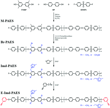 | ||
| Fig. 1 Synthetic procedure of end-group cross-linkable imidazolium functionalized poly(arylene ether sulfone) copolymer. | ||
In this work, the synthesized copolymers were composed of TMBP, BP and DFDPS with two different degrees of functionalization. Table S1 (ESI†) summarizes the properties of the synthesized polymers and the respective membranes. The synthesized polymers exhibited high MWs above 177 kDa with PDI values between 2.3–2.5.
The structure of 3-hydroxyphenylacetylene in Na+ salt form was confirmed by 1H-NMR by using D2O as a solvent (see Fig. S1, ESI†). Notably, the tailor-made end-group cross-linker in this work reacted easily with the –F terminated copolymers at RT without the need for an additional base such as K2CO3. It should be stressed that using such a base inevitably induces unwanted gelation due to interactions with the cationic functional groups. The structures of the synthesized polymers (M-PAES, Br-PAES, Imd-PAES and E-Imd-PAES) were checked by 1H-NMR in DMSO-d6 (see Fig. S2, ESI†). The M-PAES60 showed a strong –CH3 peak at 2.1 ppm. After the benzylic bromination step, the peak corresponding to −CH2Br appeared at 4.2 ppm. The methyl (−CH3) peak at 2.1 ppm was smaller than half of that observed in the M-PAES. For Imd-PAES, the −CH2− Imd peak (Ha) shifted from 4.2 to 5.4 ppm, and (Hg), (Hh), (Hi) and (Hj) appeared at 8.4, 7.5, 3.7, and 9.2 ppm, respectively, due to the attached 1-methylimidazole. The triple bond peak (Hk) of the final E-Imd60 was confirmed at 4.4 ppm.
Thermal trimerization
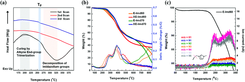
Scheme 2 shows the schematic concept and resulting polymer structure after end-group cross-linking by thermal treatment. As shown, a benzene group connects the three end-groups. It should be noted that the alkyne trimerization reaction occurs in the already-formed membrane state (solid state).8,19,30 As shown in Fig. 2(a), the broad curing peak for E-Imd60 sample was clearly visible in the first DSC cycle at 200 °C, resulting from the alkyne trimerization reaction. Successively, a downward slope can be seen from 275 °C to 325 °C due to the decomposition of imidazolium groups. This type of curing peak was not observed in the second and third scanning cycle, while a Tg (260.5 °C) signal was observed. Hence, despite the high molecular weight, we concluded that the end-groups have been fully cross-linked in the first cycle.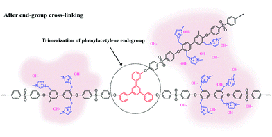 | ||
| Scheme 2 Schematic structure of end-group cross-linked anion exchange membrane (XE-Imds) by alkyne trimerization. | ||
Fig. 2(b) presents TGA curves of pristine E-Imd60, 70 and cross-linked XE-Imd60, 70. The cross-linked membranes exhibited a small amount of weight loss in all temperature ranges. As shown in Table S1 (ESI†), the Td5% of XE-Imds were higher than those of the pristine E-Imds. In particular, XE-Imds exhibited a larger remaining weight (>35%) after reaching 800 °C than those of the other E-Imds (10–25%). In addition, the decomposition of imidazolium groups was observed between 200 °C to 300 °C using TG-MS, as shown in Fig. 2(c). It can be seen that various m/z were observed after 200 °C (m/z = 81, 91–96). Most of these are related to the pyrolyzed products (see Fig. S3, ESI† for the possible structure of pyrolyzed 1-methylimidazole). As shown in Fig. 2(c), m/z = 94 and 96 were major pyrolyzed products.
Cross-linking studies and properties
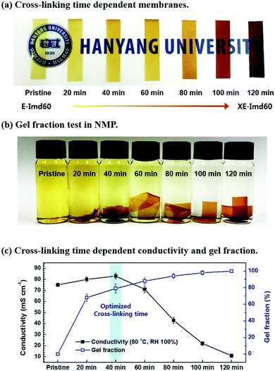
DSC and TGA data show that thermal cross-linking conditions need to be carefully optimized to avoid decomposition of imidazolium groups. As shown in Fig. 3(a), the color of the E-Imd60 (OH− form) membrane drastically changed with cross-linking time. Fig. 3(c) summarizes the hydroxide conductivity of the membranes cross-linked at 180 °C at different times. Similar to the previously-studied PEM data,8,19,26,27 the hydroxide conductivity (80 °C, RH 100%) increased up to a cross-linking time of 40 minutes, followed by a rapid decrease. Such a decrease in anionic conductivity can be attributed to the aforementioned decomposition of imidazolium groups. At the same time, the gel fraction test was performed, as shown in Fig. 3(b). The pristine membrane dissolved completely in NMP, but the gel fraction increased with increasing cross-linking time as expected.The mechanical properties of the prepared membranes are summarized in Table S2 and Fig. S4 (ESI†). As shown, the elongation at break for both E-Imds decreased after cross-linking, while the tensile strength of XE-Imds increased after cross-linking. Generally, XE-Imd60 showed a higher tensile strength than XE-Imd70, and the decrease in elongation at break was larger for XE-Imd70. Such a trend usually follows the degree of functionalization. Despite the high functionalization, XE-Imds exhibited a robust tensile strength value (≥60.2 MPa) and a high compliance elongation at break (≥16.1%).
The prepared membranes were characterized by measuring their densities, IECs, water uptake and swelling behaviors, which are essential characteristics for polymer electrolyte membranes (see Tables S3 and S4, ESI†). Upon cross-linking, XE-Imds showed slightly higher density than E-Imds, but IECw decreased due to decomposition of imidazolium groups after thermal treatment at 180 °C. Meanwhile, the IECv(dry) values for both XE-Imds exhibited similar values due to their increased density caused by cross-linking.
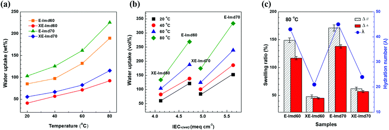
On the other hand, a significant difference was observed for the water uptake values after cross-linking. As shown in Fig. 4(a), the weight and volume based water uptakes of XE-Imds decreased by half, likely due to the condensed chain matrix formed by cross-linking. As a result, XE-Imds showed lower water uptake and lower IECv(wet) values than E-Imds. As shown in Fig. 4(b), there was a larger gap between water uptake of E-Imds and XE-Imds at 80 °C than at lower temperatures.
Fig. 4(c) presents the in-plane swelling ratio (Δ‖) and through-plane changes (Δ⊥) of E-Imds and XE-Imds at 80 °C. Corresponding to the water uptake results, X-Imds showed dramatically reduced swelling ratios upon cross-linking, and isotropic behaviors were observed, meaning that Δ‖ = Δ⊥. The calculated hydration numbers at 80 °C are plotted in Fig. 4(c), and these numbers confirmed that the amount of water uptake decreased significantly after end-group cross-linking. Note that the hydration number represents the number of water molecules per functional group. Water molecules in the functional group decreased by half from ∼45 in E-Imds to 20–22 for XE-Imds.
Hence, we concluded that end-group cross-linking improved the dimensional stability with lower water uptake and a lower hydration number. Notice that large dimensional changes or swelling, in particular in-plane swelling (Δ‖), in a membrane electrode assembly (MEA) may trigger undesired peeling of the catalytic layer from the membrane and cause poor electrochemical performance. Therefore, achieving suitable water uptake and dimensional changes by controlling the IEC or modifying the polymer by cross-linking is essential for fuel cell operation.
Morphological studies
TEM measurements were performed to observe nano-sized hydrophilic/hydrophobic phase separation, and images of E-Imds and XE-Imds are shown in Fig. 5(b). Non-cross-linked pristine E-Imd60 and 70 showed a randomly dispersed morphology. As expected, E-Imd70 exhibited a slightly increasing hydrophilic cluster size (dark region, 6–9 nm) due to the higher degree of functionalization compared to the size of E-Imd60 (4–6 nm). However, after thermal treatment, XE-Imds completely changed to the well assorted and nano-phase separated morphology by transformation of the polymer chain matrix. In consecutive casting and thermal treating processes, movable three end-groups from different polymer chains were aggregated and formed a benzene ring through alkyne trimerization.Three-pronged chains were connected around the cross-linking site, where imidazolium groups from different chains were rearranged during thermal transformation. Certainly, XE-Imds showed differentiated ionic clustered morphologies compared with pristine E-Imds. Connected larger domains were observed in both XE-Imds. In particular, XE-Imd70 showed a larger (8–15 nm) and more clearly separated morphology than XE-Imd60 (7–12 nm) due to its higher IECw. Note that in our earlier study, end-group cross-linked PEM (sulfonated poly(phenylene sulfide sulfone)) showed a significantly transformed ionic clustered morphology and increased cluster size by thermal end-group cross-linking as in the present case for XE-Imds.8,19
In order to identify the size of the ionic clustered morphologies, SAXS analysis of E-Imds and XE-Imds was performed, as displayed in Fig. 5(c). The SAXS patterns exhibited notably different shapes between E-Imds and XE-Imds as in the TEM images. Pristine E-Imd60 and 70 showed typical patterns of random copolymers as the peak contrast intensity q (max) values were relatively low. As expected, E-Imd70 showed a larger inter-cluster distance (d = 8.3 nm) than E-Imd60 (d = 5.5 nm) due to the higher IECw. After thermal end-group cross-linking, XE-Imds exhibited a sharp peak around the q (max) value. In particular, d values were shifted to the left side of the X-axis (q). XE-Imd60 and 70 showed q (max) values at 0.52 and 0.44 nm−1, corresponding to inter-cluster distances of 12.1 and 14.3 nm, respectively. It is evident that the polymer matrix can be effectively rearranged to form larger ionic domains or clusters through morphological transformations during cross-linking. Thus, the connected ion-clustered morphology was supported by evidence from both TEM results in Fig. 5(b) and SAXS results in Fig. 5(c).
Fuel (i.e., hydrogen) permeability of E-Imd60 and XE-Imd60 was 1.6 and 2.5 Barrer (1 Barrer = 10−10 cm3 (STP) cm cm−2 s−1 cmHg−1) (see Table S5, ESI†) whereas that of Nafion® 212 was 6.7 Barrer, which is in good agreement with the result from the literature,33 indicating an enhancement in hydrogen barrier properties of the present aromatic hydrocarbon membranes compared to the Nafion® 212. Obviously, the end-group cross-linking step induced the resulting membranes with larger tortuosity and fractional free volume from end-group cross-linking.33,34
Electrochemical performance
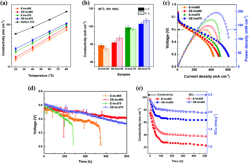
Fig. 6 summarizes the electrochemical performances of the prepared membranes. The temperature-dependent hydroxide conductivities were also measured with Nafion® 212 as a reference. As shown in Fig. 6(a) and (b) and Table S4 (ESI†), each XE-Imd showed higher conductivity over all the temperature ranges than that of E-Imd despite the lower water content. These aspects can be attributed to the effect of morphological transformation after cross-linking. Typically, a high proton conductivity in PEMs (≥200 mS cm−1) can be easily achieved at 80 °C under 100% RH. The hydroxide conductivity of AEMs, however, is much lower than the proton conductivity of the PEMs, typically in the range of about 60–100 mS cm−1, due to the conducting kinetics of hydroxide ions.3,11,12 A high conductivity is required for efficient fuel cell operation. The XE-Imd70 membrane achieved high hydroxide conductivities of 103 ms cm−1 (σ‖) and 107 ms cm−1 (σ⊥) at 80 °C. Interestingly, a reversing phenomenon between σ‖ and σ⊥ was observed. XE-Imds exhibited higher σ⊥ than σ‖, corresponding to the swelling behavior. Note that the higher σ⊥ could be due to the ion clustered morphology, which provides favorable through-plane conductivity during transformation.Fig. 6(c) displays single cell IV curves of E-Imds and XE-Imds at 80 °C and 100% RH. The differences in electrochemical performance corresponded to the IEC and conductivity values of the membranes. In the conductivity experiments, the end-group cross-linked XE-Imds showed an increase in current density and power density in the actual operating conditions in the presence of fuels. It is clear that the increase in through-plane conductivity affects the actual OH− transfer in fuel cell operation. In addition, in the low voltage region, both XE-Imd60 and 70 exhibited higher current densities than those of E-Imds. This may be attributed to effective water management of XE-Imd membranes at the anode side by preventing water flooding. Dramatically reduced swelling behavior in XE-Imds makes it possible to generate higher energy in a broad voltage range. The highest performance for the XE-Imd70 membrane measured at 0.6 V was observed with a current density of 202 mA cm−2 and a maximum power density of 196.1 mW cm−2 (H2/air condition). This electrochemical performance result is the highest compared to previous AFC studies reported so far.3,6,12,13,32
Single cell durability tests were performed to verify the effect of end-group cross-linking in E-Imd PAES AEMs. Each MEA was tested at 80 °C and RH 100%. The voltage drop was measured at a constant current (0.2 A cm−2) in a manner similar to the previous studies.19,27,35 As shown in Fig. 6(d), the initial voltages of XE-Imd70 were similar, showing slightly higher values than the other samples (0.6–0.63 V). After operating for 100 h, the non-cross-linked E-Imds showed a steeper decline in voltage. The electrochemical performance of E-Imd70 degraded near 300 h, followed by E-Imd60 at 500 h. On the other hand, XE-Imds showed a very gradual voltage drop. Both XE-Imd60 and 70 achieved much longer durability and operated over 800 h. Note that the alkaline fuel cell operation was stopped at 800 h. In addition, excellent isotropic swelling behavior of XE-Imds (Δ‖ = Δ⊥) helped to ensure durable AFC operation. Additionally, the starting voltages of XE-Imd70 were higher than those of XE-Imd60; however, after 400 h, this downward trend was reversed due to the degree of imidazolium groups.
Fig. 6(e) displays the alkaline stability analyzed by hydroxide conductivity at 80 °C, 100% RH and the IECw data as a function of alkaline exposure time. The XE-Imd60 exhibited relatively low decreases in hydroxide conductivity and IECw over time. The XE-Imd60 showed stabilized IECw values of 2 meq g−1 and a hydroxide conductivity of 67 mS cm−1. But, the E-Imd60 stabilized at an IECw of 1.3 meq g−1 and a hydroxide conductivity of 27 mS cm−1. In conclusion, the XE-Imd60 membrane showed the highest performance among the tested membranes even in electrochemically harsh alkaline environments.
Conclusions
In this work, the end-group cross-linking method was applied for the first time in AEM using a tailor-made sodium salt of 3-hydroxyphenylacetylene as a cross-linker. A novel imidazolium-functionalized end-group cross-linked AEM (XE-Imds) achieved highly conducting electrochemical performance comparable to that of CEMs. In addition, improvements in electrochemical performances, single cell durability and alkaline stability of XE-Imds were demonstrated. These improvements were mainly attributed to the morphological transformation after cross-linking of E-Imds. Using thermal alkyne trimerization, an optimum temperature and cross-linking time were determined to prevent thermal decomposition of imidazolium groups while maximizing the performance. Correlations between cross-linking time and electrochemical performance were analyzed using hydroxide conductivity measurements. The optimized XE-Imds showed higher conductivity (XE-Imd70: 107 ms cm−1 at 80 °C under RH 100%) and single cell performance (XE-Imd70: 202 mA cm−2 at 0.6 V and maximum power density of 196.1 mW cm−2) than those of E-Imds (E-Imd70: 184 mA cm−2 at 0.6 V and maximum power density of 170.7 mW cm−2). This was attributed to the differences in the isotropic swelling ratio of XE-Imds compared with pristine E-Imds. Note that through-plane conductivities of XE-Imds improved compared with in-plane conductivities after cross-linking, indicating a favorable ion conduction for XE-Imds. We believe that further studies using this novel end-group cross-linking concept in AEM will be conducted in other fields using ion exchange membranes such as electrodialysis (ED), reverse electrodialysis (RED), redox flow batteries and non-soluble ionic materials.Acknowledgements
This work was supported by the Nano Material Technology Development Program (2012M3A7B4049745) through the National Research Foundation funded by the Ministry of Science, ICT and Future Planning. The small-angle X-ray scattering (SAXS) experiments at PLS-II (Beamline 4C) performed at the Pohang Accelerator Laboratory (PAL) were supported in part by the Ministry of Science, ICT and Future Planning and Pohang Steel Co. Ltd.References
- H. Zhang and P. K. Shen, Chem. Soc. Rev., 2012, 41, 2382–2394 RSC.
- C. H. Park, C. H. Lee, M. D. Guiver and Y. M. Lee, Prog. Polym. Sci., 2011, 36, 1443–1498 CrossRef CAS.
- G. Couture, A. Alaaeddine, F. Boschet and B. Ameduri, Prog. Polym. Sci., 2011, 36, 1521–1557 CrossRef CAS.
- C. H. Park, S. Y. Lee, D. S. Hwang, D. W. Shin, D. H. Cho, K. H. Lee, T. W. Kim, T. W. Kim, M. Lee, D. S. Kim, C. M. Doherty, A. W. Thornton, A. J. Hill, M. D. Guiver and Y. M. Lee, Nature, 2016, 532, 480–483 CrossRef PubMed.
- Y. M. Lee, Nat. Energy, 2016, 1, 16136 CrossRef.
- J. Pan, C. Chen, Y. Li, L. Wang, L. Tan, G. Li, X. Tang, L. Xiao, J. Lu and L. Zhuang, Energy Environ. Sci., 2014, 7, 354–360 CAS.
- K.-S. Lee, J. S. Spendelow, Y.-K. Choe, C. Fujimoto and Y. S. Kim, Nat. Energy, 2016, 1, 16120 CrossRef.
- S. Y. Lee, N. R. Kang, D. W. Shin, C. H. Lee, K.-S. Lee, M. D. Guiver, N. Li and Y. M. Lee, Energy Environ. Sci., 2012, 5, 9795 CAS.
- N. Li, T. Yan, Z. Li, T. Thurn-Albrecht and W. H. Binder, Energy Environ. Sci., 2012, 5, 7888 CAS.
- N. Li, L. Wang and M. Hickner, Chem. Commun., 2014, 50, 4092–4095 RSC.
- K. Matsumoto, T. Fujigaya, H. Yanagi and N. Nakashima, Adv. Funct. Mater., 2011, 21, 1089–1094 CrossRef CAS.
- O. I. Deavin, S. Murphy, A. L. Ong, S. D. Poynton, R. Zeng, H. Herman and J. R. Varcoe, Energy Environ. Sci., 2012, 5, 8584 CAS.
- J. R. Varcoe, P. Atanassov, D. R. Dekel, A. M. Herring, M. A. Hickner, P. A. Kohl, A. R. Kucernak, W. E. Mustain, K. Nijmeijer, K. Scott, T. Xu and L. Zhuang, Energy Environ. Sci., 2014, 7, 3135–3191 CAS.
- J. Pan, Y. Li, J. Han, G. Li, L. Tan, C. Chen, J. Lu and L. Zhuang, Energy Environ. Sci., 2013, 6, 2912 CAS.
- N. Li, Y. Leng, M. A. Hickner and C. Y. Wang, J. Am. Chem. Soc., 2013, 135, 10124–10133 CrossRef CAS PubMed.
- O. D. Thomas, K. J. Soo, T. J. Peckham, M. P. Kulkarni and S. Holdcroft, J. Am. Chem. Soc., 2012, 134, 10753–10756 CrossRef CAS PubMed.
- J. Yang, Q. Li, L. N. Cleemann, J. O. Jensen, C. Pan, N. J. Bjerrum and R. He, Adv. Energy Mater., 2013, 3, 622–630 CrossRef CAS.
- W. Ma, C. Zhao, J. Yang, J. Ni, S. Wang, N. Zhang, H. Lin, J. Wang, G. Zhang, Q. Li and H. Na, Energy Environ. Sci., 2012, 5, 7617 CAS.
- D. W. Shin, S. Y. Lee, N. R. Kang, K. H. Lee, D. H. Cho, M. J. Lee, Y. M. Lee and K. D. Suh, Int. J. Hydrogen Energy, 2014, 39, 4459–4467 CrossRef CAS.
- T. Ko, K. Kim, B.-K. Jung, S.-H. Cha, S.-K. Kim and J.-C. Lee, Macromolecules, 2015, 48, 1104–1114 CrossRef CAS.
- L. Wang and M. A. Hickner, Polym. Chem., 2014, 5, 2928 RSC.
- D. Henkensmeier, H. Cho, M. Brela, A. Michalak, A. Dyck, W. Germer, N. M. H. Duong, J. H. Jang, H.-J. Kim, N.-S. Woo and T.-H. Lim, Int. J. Hydrogen Energy, 2014, 39, 2842–2853 CrossRef CAS.
- H. Xie, D. Wang, D. Tao and L. Wang, J. Power Sources, 2014, 262, 328–337 CrossRef CAS.
- X. Lin, J. R. Varcoe, S. D. Poynton, X. Liang, A. L. Ong, J. Ran, Y. Li and T. Xu, J. Mater. Chem. A, 2013, 1, 7262 CAS.
- B. P. Tripathi, M. Kumar and V. K. Shahi, J. Membr. Sci., 2010, 360, 90–101 CrossRef CAS.
- K.-S. Lee, M.-H. Jeong, J.-P. Lee and J.-S. Lee, Macromolecules, 2009, 42, 584–590 CrossRef CAS.
- N. R. Kang, S. Y. Lee, D. W. Shin, D. S. Hwang, K. H. Lee, D. H. Cho, J. H. Kim and Y. M. Lee, J. Power Sources, 2016, 307, 834–843 CrossRef CAS.
- K.-S. Lee, M.-H. Jeong, J.-S. Lee, B. S. Pivovar and Y. S. Kim, J. Membr. Sci., 2010, 352, 180–188 CrossRef CAS.
- S. He, L. Liu, X. Wang, S. Zhang, M. D. Guiver and N. Li, J. Membr. Sci., 2016, 509, 48–56 CrossRef CAS.
- W. H. Lee, K. H. Lee, D. W. Shin, D. S. Hwang, N. R. Kang, D. H. Cho, J. H. Kim and Y. M. Lee, J. Power Sources, 2015, 282, 211–222 CrossRef CAS.
- H. W. Doughty, J. Am. Chem. Soc., 1924, 46, 2707–2709 CrossRef CAS.
- N. Li, M. D. Guiver and W. H. Binder, ChemSusChem, 2013, 6, 1376–1383 CrossRef CAS PubMed.
- S. Naudy, F. Collette, F. Thominette, G. Gebel and E. Espuche, J. Membr. Sci., 2014, 451, 293–304 CrossRef CAS.
- Y. Zhuang, J. G. Seong, Y. S. Do, W. H. Lee, M. J. Lee, Z. Cui, A. E. Lozano, M. D. Guiver and Y. M. Lee, Chem. Commun., 2016, 52, 3817–3820 RSC.
- G. Wang, K. H. Lee, W. H. Lee, D. W. Shin, N. R. Kang, D. H. Cho, D. S. Hwang, Y. Zhuang, Y. M. Lee and M. D. Guiver, Macromolecules, 2014, 47, 6355–6364 CrossRef CAS.
Footnote |
| † Electronic supplementary information (ESI) available: Additional details of synthesis and characterization. See DOI: 10.1039/c6ee03079c |
| This journal is © The Royal Society of Chemistry 2017 |

