
To mitigate self-discharge of lithium–sulfur batteries by optimizing ionic liquid electrolytes†
Lina
Wang
,
Jingyuan
Liu
,
Shouyi
Yuan
,
Yonggang
Wang
* and
Yongyao
Xia
*
Department of Chemistry,, Shanghai Key Laboratory of Molecular Catalysis and Innovative Materials, Institute of New Energy, and Collaborative Innovation Center of Chemistry for Energy Materials, Fudan University, Shanghai 200433, China. E-mail: ygwang@fudan.edu.cn; yyxia@fudan.edu.cn
First published on 13th November 2015
Abstract
Li–S batteries generally suffer from severe self-discharge when resting due to an internal polysulfide shuttle effect. Soluble long-chain polysulfide species (Li2Sx, 4 ≤ x ≤ 8) would continue to dissolve and migrate to the negative side to react with metallic Li. Here, we demonstrate pronounced suppression of polysulfide shuttle using an ionic liquid of the N-methyl-N-propylpiperidinium bis(trifluoromethanesulfonyl)imide (PP13TFSI)-based electrolyte. When working in combination with LiNO3, zero self-discharge can be achieved to rest a full-charged Li–S cell for two days. The fascinating study clearly demonstrates that a promising practical Li–S battery with low self-discharge depends on both improvements on polysulfide diffusion control and Li-metal stabilization.
Broader contextLithium–sulfur (Li–S) batteries are receiving tremendous attention due to their potential for high energy-density batteries in emerging electronics and vehicle applications. However, severe self-discharge associated with a rapid polysulfide redox shuttle process has remained a grand challenge, preventing the practical application of this attractive technology. Soluble polysulfide species (Li2Sx, 4 ≤ x ≤ 8) would continue to dissolve and migrate to the negative side because of concentration gradient, and then react with metallic Li, resulting in a decrease of open-circuit voltage, loss of upper discharge plateaus and discharge capacity. To address this issue, we take a different approach to the Li–S battery by developing a room temperature ionic liquid (RTIL) of N-methyl-N-propylpiperidinium bis(trifluoromethanesulfonyl)imide (PP13TFSI)-based electrolytes. When working together with LiNO3, zero self-discharge can be achieved to rest a full-charged cell for two days. From a systematic study of battery performance in terms of various kinds of electrolytes and comprehensive characterization on Li-electrodes, we conclude that both improvements on polysulfide diffusion control and stabilization of Li-metal should be fulfilled for a successful battery with low self-discharge. This approach shows the way forward to the practical use of Li–S batteries by selection and more rational design of electrolytes. |
Introduction
The exceedingly high abundance and low toxicity of sulfur makes it an attractive positive electrode candidate of extremely high specific capacity (1672 mA h g−1) for rechargeable lithium (Li) batteries.1,2 The lithium–sulfur (Li–S) battery consisting of a sulfur positive and a Li-metal negative electrode that promise a theoretical energy density of 2600 W h kg−1, through the reversible electrochemical reaction: S8 + 16Li ↔ 8Li2S, has recently attracted much attention due to its potential to meet the performance requirements for high energy-density batteries.3–7 In fact, the lithiation of sulfur is a multistage process.8–10 A series of lithium polysulfide intermediates (Li2Sx, 4 ≤ x ≤ 8) always form corresponding to varying stages of incomplete reductions of elemental sulfur (S8), where the long-chain polysulfides tend to dissolve in polar organic solvents commonly used in electrolytes.11 Their migration to and from the negative electrode creates a redox “shuttle” phenomenon that induces serious concerns over the loss of active agents, the robust parasitic reactions at the surface of metallic Li and the passivation/degradation of electrodes. As a result, the commercial use of Li–S batteries has been so far hindered by numerous problems. In particular, these include insufficient capacity retention, limited charge–discharge coulombic efficiency (CE) and severe self-discharge.The most adopted technique to address these challenges is enclosing of sulfur into an elaborate porous, conductive matrix to trap lithium polysulfides.12–16 However, complete confinement is difficult to achieve. The novel functional carbon with the ability to chemically adsorb sulfur atoms enable the effective confinement of polysulfides in positive electrodes, showing enhanced utilization of the active sulfur.5,17–19 In another direction, the performance of Li–S batteries is also greatly affected by properties of polysulfide solutions, including polysulfide solubility in electrolytes, viscosity of polysulfide solutions, and chemical compatibility between the electrolyte components and polysulfide anions.20 In other words, the dissolution and diffusion of polysulfides are determined largely by the physicochemical properties of organic electrolytes. Owing to the strongly nucleophilic reactivity of polysulfide anions, the electrolyte solvents of Li–S cells are mainly limited within the cyclic and linear ethers, such as 1,3-dioxolane (DOL) and 1,2-dimethoxyethane (DME).21,22 However, this type of electrolyte readily solubilizes the Li2Sx species (especially, x ≥ 4) and actually functions as a catholyte after the first discharge in Li–S cells.23 Consequently, promising technological contributions through modification of electrolytes have been attempted to overcome the obstacles. These include systems based on organic solvents such as new types of room temperature ionic liquids (RTILs),24–27 partially fluorinated ether,28–31 glyme–Li equimolar complexes,23,32,33 and the more highly concentrated electrolytes.34,35 In addition, researchers have examined the possibilities to isolate the Li-electrode from polysulfide species using ether-based electrolytes in the presence of the LiNO3 additive, which plays a pivotal role in the formation of a protective surface film on the surface of Li.36–38 In this case, the inhibition of the detrimental redox shuttle depends on the stability of the passivation layer during repeated charge–discharge cycles.
Nevertheless, compared with much effort to improve cycling efficiency and stability, there is still far from a clear clarification on the self-discharge issue of Li–S batteries using promising developed electrolytes. Losing capacity of a battery after storage for a certain period is generally called self-discharge. Self-discharge always occurs when Li–S batteries are resting. Sulfur or polysulfide species would continue to dissolve and migrate to the negative side because of concentration gradient, and then react with metallic Li, resulting in a decrease of open-circuit voltage (OCV), loss of upper discharge plateau and discharge capacity.11,39,40 Low self-discharge is an important criterion to judge the practicality of energy-storage devices. To understand self-discharge performance is therefore very helpful for selecting and more rational design of electrolytes towards the practical use of Li–S batteries.
Although a few studies have focused on direct investigation of self-discharge in Li–S batteries,41–47 a method of significantly suppressed self-discharge over long storage times has not been demonstrated. Here we report a strategy to efficiently mitigate the self-discharge of Li–S batteries by optimizing ionic liquid electrolytes. It is confirmed that the solubility and mobility of Li2Sx is able to impede in a RTIL of N-methyl-N-propylpiperidinium bis(trifluoromethanesulfonyl)imide (PP13TFSI), which is used as an alternative solvent for electrolytes of Li–S batteries. When working together with LiNO3, zero self-discharge is achieved to rest a full-charged cell for two days, giving superior performance. Comprehensive characterization on Li-electrodes is performed in order to understand the interaction between active Li and polysulfide solution. To evaluate the practical application of the unique PP13TFSI-based electrolyte, a comparative and systematic study of battery performance in terms of various kinds of electrolytes has also been carried out. Our investigation clearly suggests that self-discharge behaviour of batteries dramatically changes depending on physicochemical properties of electrolytes.
Experimental section
Preparation of electrolytes
All chemicals were used as received. Electrolytes were homemade from dried lithium salts and either N-methyl-N-propylpiperidinium bis(trifluoromethanesulfonyl)imide (PP13TFSI, H2O < 20 ppm, Kanto Chemical), 1,3-dioxolane (DOL, H2O < 20 ppm, provided by BASF) or 1,2-dimethoxyethane (DME, H2O < 20 ppm, provided by BASF) in an Ar-filled glove box (<1 ppm of H2O and O2, Mikrouna). Lithium bis(trifluoromethanesulfonyl)imide (LiTFSI, >99.95%, Aldrich) and lithium nitrate (LiNO3, >99.99%, Aladdin) were used as salts for electrolytes. The solution of PP13TFSI/DOL/DME (2/1/1, v/v) containing 1 M LiTFSI (with or without 0.2 M LiNO3) was designed and prepared for Li–S cells. The reference electrolytes, including DOL/DME (1/1, v/v) containing 1 M LiTFSI, the highly concentrated DOL/DME (1/1, v/v) containing 3 M LiTFSI, and the DOL/DME (1/1, v/v) containing 0.2 M LiNO3 and 1 M LiTFSI, were also prepared.Preparation of sulfur electrodes
Positive electrodes for Li–S coin cell tests were prepared by mixing 60 wt% of commercial sulfur (99% purity, sublimed, Wako) and 40 wt% of Ketjenblack (KB) carbon powder in N-methyl-2-pyrrolidone (NMP) thoroughly to make a slurry. The slurry was then cast on one side of glass fiber (Whatman, GF/C)48 and dried in a vacuum drier at 50 °C for 12 h for the evaporation of NMP. The dried electrodes were punched into discs with a diameter of 14 mm. Sulfur loading is around 3 mg cm−2.Li–S cell assembly and electrochemical measurements
The electrochemical performance was examined at room temperature of 25 °C. For Li–S coin cells assembly, aluminium foil (as a current collector, d (diameter) = 14 mm), a sulfur electrode on a glassy fiber paper (as an electrode substrate and separator, d = 14 mm), one sheet of microporous membrane (as a separator, d = 18 mm, 25 μm-thick, Celgard 2325), and metallic Li (as an negative electrode, d = 14 mm) were sequentially assembled to CR2016-type coin cells in an Ar-filled glove box. All cell types with various electrolytes used the same amount electrolyte of 100 μL, which were controlled by the use of a microsyringe. The cells were examined immediately after assembling before any electrochemical measurements. Galvanostatic cycling were operated in the voltage range between 1.7–2.7 V or 1.5–3.0 V (vs. Li/Li+) on a LAND CT2001A Battery Cycler (Wuhan, China). Based on the mass of elemental sulfur, the gravimetric current density of 1672 mA g−1 was defined as 1 C rate. Electrochemical Impedance Spectroscopy (EIS) was measured at open-circuit voltage (OCV) on a CHI 660E Electrochemical Workstation (CHInstruments, USA) in the frequency range of 100 mHz−1 to 1 MHz at a potentiostatic signal amplitude of 5 mV.Characterization
The viscosity was measured using a Rheometer (Anton Paar Physica MCR301) with a shear rate of 10 s−1 at 25 °C. Following galvanostatic cycling for 10 cycles, the Li–S cells were disassembled in the Ar-filled glove box. The Li-negative electrodes were washed with DME and dried in a glove box. Except the cross-sectional view, other characterization was conducted to examine the Li-electrode surfaces facing the positive electrode. Scanning electron microscopy (SEM) was performed in a clean room using a scanning microscope (Hitachi, FE-SEM S-4800). Fourier transform infrared (FTIR) spectra were performed on a Thermo Scientic Nicolet 6700 FT-IR Spectrometer. X-ray spectra (XPS) were performed on a photoelectron spectrometer (Axis Ultra DLD). Monochromatic Al-Kα was used as excitation. The typical analysis area is 300 × 700 μm in diameter and the pressure for the analysis chamber is 10−9 mbar.Results and discussion
In order to promote reliable Li–S batteries without sophisticated sulfur confinement, we used commercial available micro-sized sulfur that has no controlled morphology (Fig. S1, ESI†) as an active material for positive electrodes. RTILs consist of entirely cations and anions, which are different from conventional molecular solvents such as DOL and DME (Fig. S2, ESI† see the chemical formula). Typical RTILs are highly stable, non-flammable, negligibly volatilizable and remain in liquid form over a wide temperature range.24–27 Quaternary ammonium-imide RTILs have been the most attractive because the cathodic stability against Li-metal for electrochemical devices.49,50 Among the group, PP13TFSI (Fig. S2, ESI† see the chemical formula) has a wide electrochemical window from −0.26 to 5.94 V (vs. Li/Li+) and can work as an electrolyte base for Li batteries.24,50,51 Nevertheless, previous Li–S studies show that high viscous electrolytes result in poor electrochemical performance, especially in terms of sulfur utilization.24,26 As demonstrated in Fig. 1, the charge–discharge voltage profiles with PP13TFSI–1 M LiTFSI manifest a smaller value of initial discharge capacity and a larger overpotential between discharge and charge plateaus at 0.1 C (1 C = 1672 mA g−1) than that at 0.05 C. The high viscosity of PP13TFSI (117 cP at 25 °C) may slow down Li+ transport in electrolytes and hence prevent rapid charge–discharge of cells. The sluggish discharge curve for the first cycle at 0.1 C may be caused by the slow Li+ transfer kinetics to form the resistive discharge products (Li2S2/Li2S) in the high viscous electrolyte.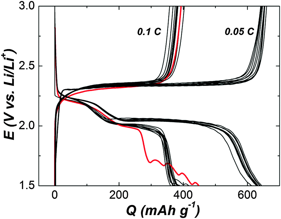 | ||
| Fig. 1 Charge–discharge voltage profiles of the Li–S cell with PP13TFSI–1 M LiTFSI. The initial 10 cycles operate at a current rate of 0.1 C (red line is the first cycle) and the subsequent 10 cycles at 0.05 C. | ||
So as to use PP13TFSI in a cell, a combination of low viscous ethers of DOL and DME (0.6 and 0.46 cP at 25 °C for DOL and DME, respectively) with the RTIL of PP13TFSI unveils a new class of Li–S battery electrolytes. For example, blending PP13TFSI with DOL/DME (2/1/1, v/v) enable us to get a less viscous mixed solvent (5 cP at 25 °C) than single PP13TFSI. In the present study, the solution of PP13TFSI/DOL/DME (2/1/1, v/v)–1 M LiTFSI (with or without 0.2 M LiNO3) was employed as electrolytes for Li–S batteries. For reference electrolytes, the conventional DOL/DME (1/1, v/v)–1 M LiTFSI was used as a baseline electrolyte (the cell using the electrolyte is called a baseline cell). Other two electrolyte types, i.e., the highly concentrated solution of DOL/DME (1/1, v/v)–3 M LiTFSI and DOL/DME (1/1, v/v)–0.2 M LiNO3–1 M LiTFSI were also prepared (the ration of solvents and the concentration of lithium salts is omitted in subsequent denotations). Electrochemical impedance spectra (EIS) were conducted on Li–S cells with various electrolytes (Fig. S3, ESI†). Distinguished from the baseline cell, the interfacial resistance in the Nyquist plot is lower for that with the widely adopted LiNO3-added DOL/DME. However, the value is around twice as large to increase LiTFSI concentration to 3 M in contrast to the baseline cell. And the interfacial resistance is slightly increased for the cell with PP13TFSI as a co-solvent compared with the baseline cell. Surprisingly, the resistance is also reduced with addition of LiNO3 to the PP13TFSI-based solution. In brief, all the cells using electrolyte solution possessing LiNO3 show decreased interfacial resistance in contrast to the cells without additives for a given electrolyte with the same salt and solvent. It has been investigated comprehensively that LiNO3 is participated in the formation of an effective protective film on the surface of the Li-electrode, which enhances the stability of the metallic Li and the cycle lifetime of the battery.36–38 The protective film can be formed even for an inactivated cell. As shown in Fig. S4 (ESI†), approaching 100% CE (CE is defined as the ratio of charge capacity to discharge capacity, i.e., Qcharge/Qdischarge) can be obtained for the cell with a treated Li-electrode, which was immersed in DOL/DME–LiNO3–LiTFSI for one day before assembled to a cell using the baseline electrolyte. Evidently, the cell using Li-metal without pretreatment shows inferior charge–discharge efficiency. The result is in good agreement with the report by Xiong et al.52 This can be naturally interpreted as a pronounced effect of LiNO3 on the Li-surface chemistry, which leads to the formation of surface films with different transport properties of Li+ ions.
To operate the cells in galvanostatic cycling at a current rate of 0.5 C in the voltage range of 1.7–2.7 V without interruption (Fig. 2), the cells with modified electrolytes exhibit improved CE. The baseline cell shows around 120% CE after initial cycles, reflecting remarkable redox activity characterized by obvious overcharge. The long-chain polysulfides oxidized from active sulfur would diffuse to the Li surface, where parasitic reactions occur. The short-chain polysulfides produced by the parasitic reactions would diffuse back to the positive electrode to regenerate long-chain polysulfides. This cyclic process goes on continually leading to severe overcharge of the Li–S battery. The approach to increase LiTFSI concentration dose can ameliorate the CE to 105%, suggesting the decreased polysulfide dissolution.34,35 Better 100% CE can be achieved for the cell using PP13TFSI/DOL/DME–LiTFSI. To confirm the effect of PP13TFSI on the cell performance, the solubility test was conducted by synthesizing 0.5 M of Li2Sx (Li2Sx solution was prepared from stoichiometric mixtures of Li2S and S8 with a molar ration of 8![[thin space (1/6-em)]](https://www.rsc.org/images/entities/char_2009.gif) :7, which corresponds to the average composition of Li2S8) in the DOL/DME or PP13TFSI/DOL/DME mixture solvent according to the method reported by Rauh et al.20 It should be noted that here a “mixture” of polysulfides with different chain-lengths rather than the nominal Li2Sx composition is obtained because of the disproportional reaction.53 The images after 24 h of standing are shown in Fig. 3a. Most of Li2S8 is dissolved in DOL/DME solvent with negligible precipitation, giving rise to a dark-brown solution. Less dissolution is expected in the solvent of PP13TFSI/DOL/DME by the more precipitation observed at the vial bottom. Here, the solubility of Li2S8 is estimated to be approximately 0.3 M in the mixture solvent of PP13TFSI/DOL/DME, while that is around 0.45 M in DOL/DME (see ESI† for detailed measurements). It is concluded that the high solubility of Li2Sx in DOL/DME result in a rapid diffusion of polysulfide species into the electrolyte. Instead, the large ratio of PP13TFSI leads to less polysulfide dissolution and slower diffusion speed of polysulfides. The function mechanism is proposed in the schematic illustration of Fig. 3b.
:7, which corresponds to the average composition of Li2S8) in the DOL/DME or PP13TFSI/DOL/DME mixture solvent according to the method reported by Rauh et al.20 It should be noted that here a “mixture” of polysulfides with different chain-lengths rather than the nominal Li2Sx composition is obtained because of the disproportional reaction.53 The images after 24 h of standing are shown in Fig. 3a. Most of Li2S8 is dissolved in DOL/DME solvent with negligible precipitation, giving rise to a dark-brown solution. Less dissolution is expected in the solvent of PP13TFSI/DOL/DME by the more precipitation observed at the vial bottom. Here, the solubility of Li2S8 is estimated to be approximately 0.3 M in the mixture solvent of PP13TFSI/DOL/DME, while that is around 0.45 M in DOL/DME (see ESI† for detailed measurements). It is concluded that the high solubility of Li2Sx in DOL/DME result in a rapid diffusion of polysulfide species into the electrolyte. Instead, the large ratio of PP13TFSI leads to less polysulfide dissolution and slower diffusion speed of polysulfides. The function mechanism is proposed in the schematic illustration of Fig. 3b.
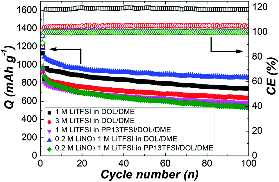 | ||
| Fig. 2 Cyclic performance of Li–S cells with various electrolytes presenting specific discharge capacity and coulombic efficiency at a current rate of 0.5 C. | ||
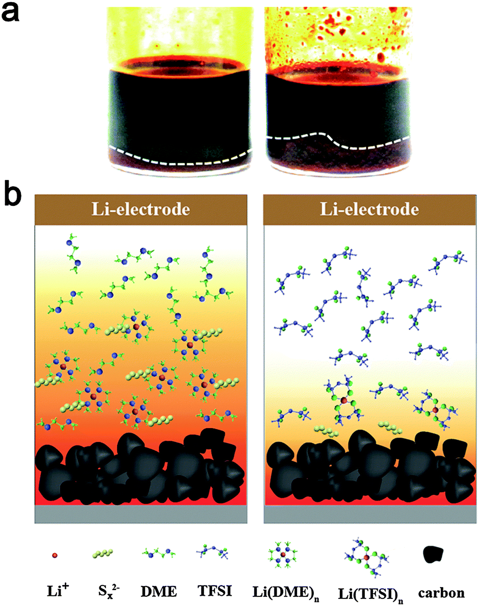 | ||
| Fig. 3 (a) Polysulfide solubility test in electrolyte solvents. 0.5 M Li2S8 (based on stoichiometric amounts of Li2S and S8) dissolved in a mixture solvent of DOL/DME (1/1, v/v) (left) or PP13TFSI/DOL/DME (2/1/1, v/v) (right). (b) Schematic illustration of the function mechanism of polysulfide dissolution and diffusion in ether (left) or PP13TFSI-based (right) solvent. | ||
The low solubility of Li2Sx in the PP13TFSI-based solution can be explained in terms of the donor ability of solvents, because dissolution of ionic Li2Sx is thought to be principally dominated by the solvation of Li+ ions of Li2Sx with solvent molecular/anions.23,26 Indeed, TFSI− anions are able to solvate the Li+ of Li2Sx through O atoms of two sulfonyl groups.54 Nevertheless, the typical RTIL of PP13TFSI consist of a weakly Lewis acidic cation and a weakly Lewis basic anion. The weakly Lewis basic nature of a TFSI− anion induces decreased coordination ability with Li+. Instead, the ether solvents have a high donor number would preferentially coordinate with Lewis acidic cations of Li+. For this reason, DME and DOL can readily solubilize Li2Sx. 100% CE also can be achieved for the cells with electrolytes containing the LiNO3 additive, implying the prohibited polysulfide shuttle. The representative galvanostatic cyclic profile at the 10th cycle for the baseline cell show more obvious polarization than other cells (Fig. S5, ESI†). The polarization indicates high cell internal resistance, which is expected owing to corrosion of metallic Li from polysulfide species during repeated dissolution and precipitation processes.
Notably, for a practical electronic device, storage of a fresh or an activated electrochemical cell is conventional. To rest a full charged cell always cause rapid high plateau capacity fade because of a higher reactivity of long-chain polysulfides (Li2Sx, x > 4).11,39,40 Therefore, to cure the self-discharge of a full charged cell represents the toughest challenge for a practical Li–S battery. For examination the self-discharge behaviour, a relatively low current rate of 0.2 C was deliberately applied to the cells in order to observe the shuttle effect in the most extreme condition. Indeed, the shuttle effect is not so serious to operate the cell at higher current density, because the diffusion of polysulfides to the Li-electrode might be slower than the total electrochemical reaction time. Fig. 4a is the discharge capacity as a function of cycle number. After uninterrupted 10 cycles, the cells were rested for 24 h, and then cycled further up to 200 cycles. The corresponding CE as a function of cycle number indicates the restrained polysulfide shuttle with modified electrolytes at the low current rate (Fig. 4b). On the first discharge after rest (11th), there is drastic capacity decay for all of the three cell types using LiNO3-free electrolytes (Fig. 4c), indicating obvious self-discharge. Accordingly, the CE on the 11th deteriorated severely (Fig. 4d). On the second discharge after rest (12th), the cells show partial recovery of the capacity. The result suggests the self-discharge more likely stems from the reversible polysulfide shuttle rather from irreversible loss of the active material. Unfortunately, the lost capacity during rest could not recover completely. For the cell types using LiNO3-added electrolytes, no obvious loss of discharge capacity after storage in the full-charged state, revealing weak self-discharge.
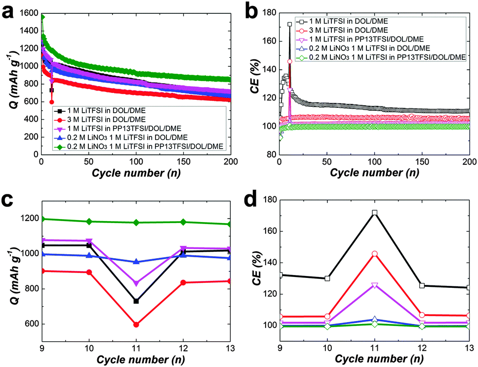 | ||
| Fig. 4 Cyclic performance of Li–S cells presenting specific discharge capacity (a) and coulombic efficiency (b) with various electrolytes at 0.2 C. (c) and (d) is the enlargement from the 9 to 13 th cycles in (a) and (b). After an uninterrupted 10 cycles, the cells were rested for 24 h, and then cycled further up to 200 cycles. | ||
For more clarify, Fig. 5(a–e) displays charge–discharge voltage profiles for various cell types at the 1st, 10, 11 and 12th cycles. The average self-discharge value of these cells is illustrated in Fig. 5f. The self-discharge rate of the baseline cell is 30% (calculated based on the ratio of discharge capacity of (Q10th–Q11th) to Q10th, i.e., (Q10th–Q11th)/Q10th, Fig. 5a). To increase the concentration of LiTFSI to 3 M alone could not alleviate self-discharge (Fig. 5b). To add PP13TFSI as a co-solvent can mitigate the self-discharge rate to 22% (Fig. 5c). However the effect is limited by merely hampering polysulfide dissolution and diffusion compared to the introduction of the LiNO3 additive (Fig. 5d), as demonstrated by 4% self-discharge rate, originating from the formation of an effective protective film on Li-metal. However, this layer still did not suffice to alleviate the self-discharge. The cell using PP13TFSI/DOL/DME–LiNO3–LiTFSI exhibits the lowest self-discharge rate of 0% (Fig. 5e). To extend the resting time to 48 h, still no noticeable self-discharge is observed (Fig. 6a and b). Further to rest a full charged cell for one week, there is only 4.7% self-discharge rate (Fig. 6c and d). Obviously, when working together with LiNO3, the PP13TFSI-based electrolyte can effectively suppress the self-discharge issue. This demonstration holds the promise for practical next-generation Li–S batteries enabling long-term storage.
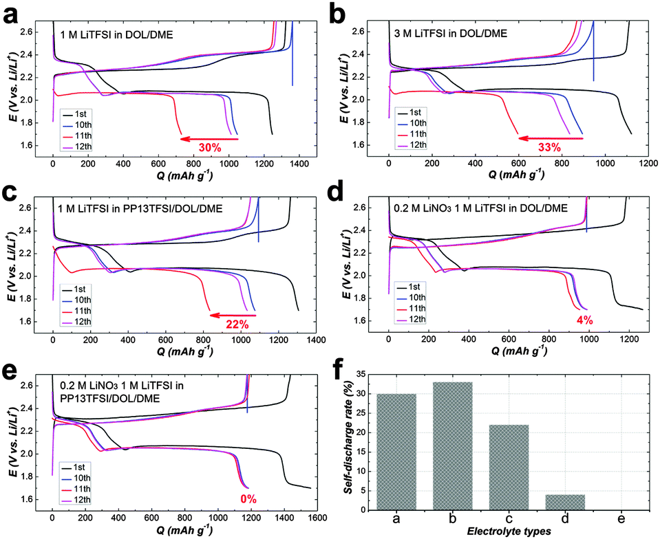 | ||
| Fig. 5 (a–e) Charge–discharge voltage profiles and average self-discharge of cells using various electrolytes with black, blue, red and magenta indicating the 1st, 10th, 11th and 12th cycles respectively. (f) Illustration of the average self-discharge value with electrolytes of (a–e). | ||
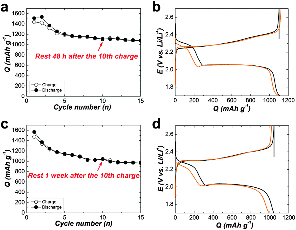 | ||
| Fig. 6 (a and c) Cyclic performance presenting specific discharge capacity of Li–S cells for 15 cycles at 0.2 C. (b and d) Charge–discharge voltage profiles of the 10th and 11th cycle. The cells were assembled with PP13TFSI/DOL/DME (2/1/1, v/v)–0.2 M LiNO3–1 M LiTFSI. After an uninterrupted 10 cycles, the cells were rested for 48 h (a and b) or one week (c and d), and then cycled further continuously. | ||
To understand the reason behind the significantly suppressed self-discharge with PP13TFSI as electrolyte base working together with the LiNO3 additive, SEM characterization was conducted to study the morphological changes on the Li-metal surfaces. The Li-electrode after 10 times of cycles in the baseline cell presents a rough surface with loosely stacked deposits in a rod shape (Fig. 7a). Less such deposits were observed on the surface of Li-metal in the additive-free PP13TFSI based electrolyte (Fig. 7b). The cycled-Li surface in the LiNO3-containing ether-based electrolyte has a much smooth surface, yet some cracks were observed (Fig. 7c). While a compact and homogeneous surface can be observed on Li cycled in the LiNO3-containing PP13TFSI-based electrolyte (Fig. 7d). The difference can be more visibly observed from the cross-section SEM images of the cycled Li-electrodes. A loose and rough passivation layer with a thickness around 30 μm can be clearly seen on the Li-electrode in the baseline cell (Fig. 8a and b). Possible explanations are the double damages from Li-dendrite formation55 and the vigorous interaction between polysulfide solution and metallic Li during cycling. The reactions between Li and polysulfides may allow the precipitation of several insoluble and nonconductive species, such as Li2S, Li2S2, and Li2S3, leading to continuous sulfur and Li loss. It also results in a continued increase in cell resistance and low CE. The loosely stacked deposits are not able to effectively prevent the polysulfide shuttle when resting the battery, thereby generating high self-discharge. In contrast, a uniform surface film with no remarkable deposits can be observed from the cross-section views of the cycled Li-electrode in the LiNO3-containing PP13TFSI-based electrolyte (Fig. 8c and d), indicating that this kind of electrolyte can effectively reduce the corrosion of Li-metal from polysulfide solution, and possibly, suppress the Li-dendrite growth.
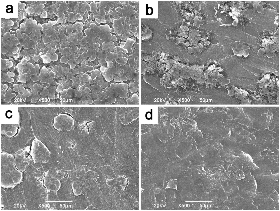 | ||
| Fig. 7 Surface SEM images of Li-electrodes from cells cycled 10 times with the electrolyte of (a) DOL/DME (1/1, v/v)–1 M LiTFSI, (b) PP13TFSI/DOL/DME (2/1/1, v/v)–1 M LiTFSI, (c) DOL/DME (1/1, v/v)–0.2 M LiNO3–1 M LiTFSI and (d) PP13TFSI/DOL/DME (2/1/1, v/v)–0.2 M LiNO3–1 M LiTFSI. | ||
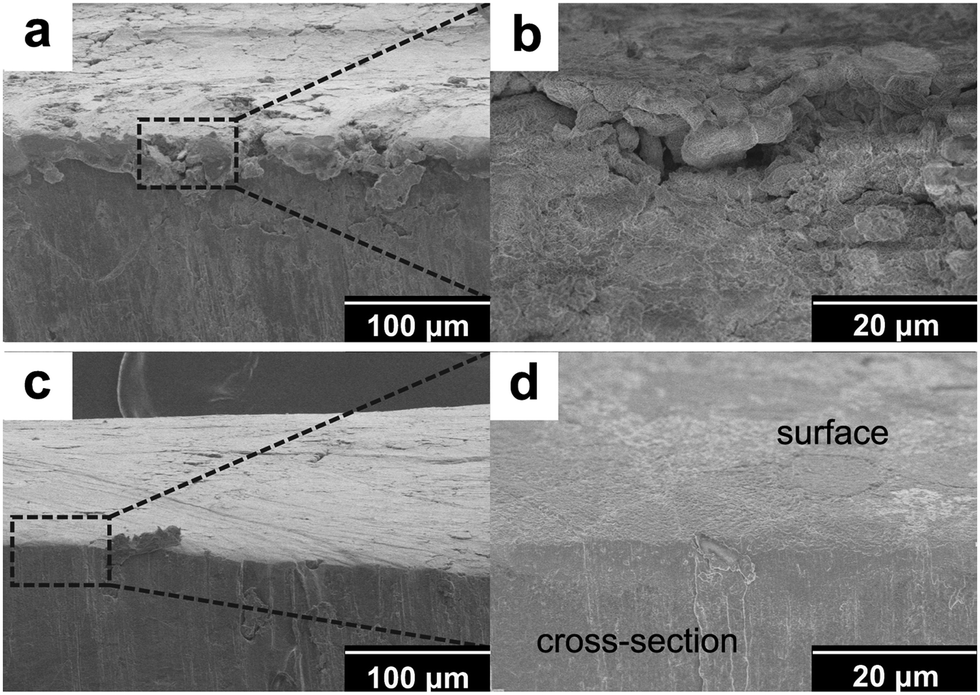 | ||
| Fig. 8 Cross-section views of Li-electrodes from cells cycled 10 times with the electrolyte of (a and b) DOL/DME (1/1, v/v)–1 M LiTFSI or (c and d) PP13TFSI/DOL/DME (2/1/1, v/v)–0.2 M LiNO3–1 M LiTFSI. (b and d) is high-magnification image of the dashed box in (a and c). | ||
To further probe these differences, we then explored Fourier-transform infrared (FTIR) spectra on these cycled Li electrodes. The νOH peaks (>3300 cm−1) in all of the spectra (Fig. S6, ESI†) reflect the inevitable presence of trace water in solutions, and hence, some surface LiOH and ROH are formed. The spectrum of the Li-electrode cycled in the baseline electrolyte (Fig. S6a, ESI†) exhibits a number of peaks which have been previously identified as belonging to components formed by reaction of polysulfides with metallic-Li and the decomposition of electrolyte solvents and salts.37,45 The spectrum suggests the formation of ROLi (νC–H), HCO2Li (νC![[double bond, length as m-dash]](https://www.rsc.org/images/entities/char_e001.gif) O, around 1620 cm−1) and ROCO2Li (νCO, around 1650 cm−1) species due to DOL/DME reduction.37 The pronounced IR peaks associated with species containing S–O (1000–1100 cm−1) and SO (670 cm−1) bonds should result from TFSI− reduction.37 Peaks lower than 500 cm−1 related to S–S bands reflect the formation of Li2S/Li2S2 as a result of Li2S6 reduction.56 The presence of PP13TFSI in solutions may affect the surface chemistry, which is well reflected by comparing FTIR spectra in Fig. S6a and b (ESI†). The structure of S–O, SO and S–S changes and the IR absorption in the region of 1000–1700 cm−1 is intensified. The peak in the 1300–1450 cm−1 region in terms of δCH, CH2, and CH3 bonds associated with HCO2Li and peaks between 900 and 1300 cm−1 related to various SO/SO2 species become better resolved. Distinguished from the spectrum of Li-metal in the baseline electrolyte, the structures of the IR peaks show pronounced changes for the cycled-Li electrodes in LiNO3-containg solutions (Fig. S6c and d, ESI†). It has been discussed in previous literature that LiNO3 can be reduced by Li to insoluble LiNxOy, Li3N and Li2O in ether-based solutions.37,52 Meanwhile, LiNO3 can oxidize LixSOy species formed by TFSI− reduction to LixSOy+1 as well as oxidize sulfur upto sulfate.37,52 In other words, the surface film formed with LiNO3 should consist of both inorganic species such as LiNxOy and organic species such as ROLi etc. Up to now, there is rare information on the surface chemistry of metallic Li in a RTIL of PP13TFSI for Li–S batteries. Here, in spite of the organic species that can be confirmed, IR spectra cannot provide sufficient information for the formation of inorganic species such as LiNxOy on the Li surface. For example, LiNxOy species should add pronounced νN–O peaks in the 1250–1000 cm−1 region. The superposition of SO2 and SO bands in the same region made the assignment of species containing N–O obscure.
O, around 1620 cm−1) and ROCO2Li (νCO, around 1650 cm−1) species due to DOL/DME reduction.37 The pronounced IR peaks associated with species containing S–O (1000–1100 cm−1) and SO (670 cm−1) bonds should result from TFSI− reduction.37 Peaks lower than 500 cm−1 related to S–S bands reflect the formation of Li2S/Li2S2 as a result of Li2S6 reduction.56 The presence of PP13TFSI in solutions may affect the surface chemistry, which is well reflected by comparing FTIR spectra in Fig. S6a and b (ESI†). The structure of S–O, SO and S–S changes and the IR absorption in the region of 1000–1700 cm−1 is intensified. The peak in the 1300–1450 cm−1 region in terms of δCH, CH2, and CH3 bonds associated with HCO2Li and peaks between 900 and 1300 cm−1 related to various SO/SO2 species become better resolved. Distinguished from the spectrum of Li-metal in the baseline electrolyte, the structures of the IR peaks show pronounced changes for the cycled-Li electrodes in LiNO3-containg solutions (Fig. S6c and d, ESI†). It has been discussed in previous literature that LiNO3 can be reduced by Li to insoluble LiNxOy, Li3N and Li2O in ether-based solutions.37,52 Meanwhile, LiNO3 can oxidize LixSOy species formed by TFSI− reduction to LixSOy+1 as well as oxidize sulfur upto sulfate.37,52 In other words, the surface film formed with LiNO3 should consist of both inorganic species such as LiNxOy and organic species such as ROLi etc. Up to now, there is rare information on the surface chemistry of metallic Li in a RTIL of PP13TFSI for Li–S batteries. Here, in spite of the organic species that can be confirmed, IR spectra cannot provide sufficient information for the formation of inorganic species such as LiNxOy on the Li surface. For example, LiNxOy species should add pronounced νN–O peaks in the 1250–1000 cm−1 region. The superposition of SO2 and SO bands in the same region made the assignment of species containing N–O obscure.
So as to investigate the complementary information of the surface film, XPS measurement was conducted from the Li surface in the LiNO3-containing PP13TFSI-based electrolyte. Fig. 9 shows Li1s, C1s, O1s, N1s and S2p spectra of the Li surface after 10 cycles. Peaks in the Li1s spectra can be assigned to Li (53 eV), Li2O (53.7 eV), ROCO2Li (54.2 eV) and Li3N (55.5 eV). For O1s and C1s spectra, except Li2CO3 (530.3 eV), all the other peaks attribute to organic species including ROLi, HCO2Li, ROCO2Li, CH3OCO2Li, RCH2OCO2Li and hydrocarbon (283.4 eV). The N1s spectrum clearly reflects the formation of inorganic species of Li3N (398.3 eV), Li2N2O2 (401.5 eV) and LiNO2 (406 eV).37,57 With regard to the S2p spectrum, the formation of sulfur species with high oxidation states should be due to the fact that NO3− acting as an oxidizer in solutions. In summary, the surface species of the Li-negative electrode contains both organic species arising from reaction between metallic Li and polysulfide solutions, and inorganic species containing LixNOy.
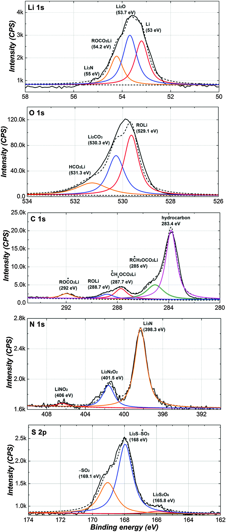 | ||
| Fig. 9 XPS spectra of the Li-electrode from the cell cycled 10 times with PP13TFSI/DOL/DME (2/1/1, v/v)–0.2 M LiNO3–1 M LiTFSI. Li1s, C1s, O1s, N1s and S2p peaks are presented including peak deconvolution and assignments. | ||
Conclusions
In this work, we demonstrate pronounced prohibited self-discharge of Li–S batteries using a RTIL of PP13TFSI-based electrolytes with the LiNO3 additive. It is anticipated that the weakly Lewis acidic/basic nature of PP13TFSI induces decreased coordination ability with a Lewis acidic cation of Li+, and thereby the solubility and mobility of Li2Sx is successfully controlled. Moreover, the compact and homogeneous surface film of cycled Li from SEM examination indicates that PP13TFSI is a potential media to suppress the local growth of Li deposition. The self-discharge rate of a full-charged cell with the LiNO3-containing ether-based electrolyte is around 4% for one day storage, while the cell using the LiNO3-containing PP13TFSI-based electrolyte displays even better zero self-discharge. On the basis of the insight gained, we suggest the ultimate success of Li–S batteries depends on both improvements on polysulfide diffusion control and stabilization of Li-metal. Therefore, selection and design of electrolytes for Li–S batteries should fulfill both demands.Acknowledgements
The authors acknowledge funding support from the Natural Science Foundation of China (21373060 and 21333002), the State Key Basic Research Program of PRC (2011CB935903, 2014CB932301), Shanghai Pujiang Program (13PJ1400800), and Shanghai Science & Technology Committee (08DZ2270500).Notes and references
- M. S. Whittingham, Chem. Rev., 2004, 104, 4271–4301 CrossRef CAS PubMed.
- P. G. Bruce, S. A. Freunberger, L. J. Hardwick and J.-M. Tarascon, Nat. Mater., 2012, 11, 19–29 CrossRef CAS PubMed.
- G. He, X. Ji and L. Nazar, Energy Environ. Sci., 2011, 4, 2878–2883 CAS.
- S. Wei, H. Zhang, Y. Huang, W. Wang, Y. Xia and Z. Yu, Energy Environ. Sci., 2011, 4, 736–740 CAS.
- J. Guo, Z. Yang, Y. Yu, H. D. Abruña and L. A. Archer, J. Am. Chem. Soc., 2013, 135, 763–767 CrossRef CAS PubMed.
- A. Manthiram, Y. Fu and Y.-S. Su, Acc. Chem. Res., 2013, 46, 1125–1134 CrossRef CAS PubMed.
- F. Zhang, X. Zhang, Y. Dong and L. Wang, J. Mater. Chem., 2012, 22, 11452–11454 RSC.
- J. Gao, M. A. Lowe, Y. Kiya and H. D. Abruña, J. Phys. Chem. C, 2011, 115, 25132–25137 CAS.
- J. Nelson, S. Misra, Y. Yang, A. Jackson, Y. Liu, H. Wang, H. Dai, J. C. Andrews, Y. Cui and M. F. Toney, J. Am. Chem. Soc., 2012, 134, 6337–6343 CrossRef CAS PubMed.
- H.-L. Wu, L. A. Huff and A. A. Gewirth, ACS Appl. Mater. Interfaces, 2015, 7, 1709–1719 CAS.
- Y. V. Mikhaylik and J. R. Akridge, J. Electrochem. Soc., 2004, 151, A1969–A1976 CrossRef CAS.
- X. L. Ji, K. T. Lee and L. F. Nazar, Nat. Mater., 2009, 8, 500–506 CrossRef CAS PubMed.
- H. Wang, Y. Yang, Y. Liang, J. T. Robinson, Y. Li, A. Jackson, Y. Cui and H. Dai, Nano Lett., 2011, 11, 2644–2647 CrossRef CAS PubMed.
- J. Ma, Z. Fang, Y. Yan, Z. Yang, L. Gu, Y.-S. Hu, H. Li, Z. Wang and X. Huang, Adv. Energy Mater., 2015, 5, 1500046, DOI:10.1002/aenm.201500046.
- S. Xin, L. Gu, N. H. Zhao, Y. X. Yin, L. J. Zhou, Y. G. Guo and L. J. Wan, J. Am. Chem. Soc., 2012, 134, 18510–18513 CrossRef CAS PubMed.
- W. Zhou, Y. Yu, H. Chen and F. J. DiSalvo, and H. D. Abruña, J. Am. Chem. Soc., 2013, 135, 16736–16743 CrossRef CAS PubMed.
- L. Ji, M. Rao, H. Zheng, L. Zhang, Y. Li, W. Duan, J. Guo, E. J. Cairns and Y. Zhang, J. Am. Chem. Soc., 2011, 133, 18522–18525 CrossRef CAS PubMed.
- J. Song, T. Xu, M. L. Gordin, P. Zhu, D. Lv, Y.-B. Jiang, Y. Chen, Y. Duan and D. Wang, Adv. Funct. Mater., 2014, 24, 1243–1250 CrossRef CAS.
- J. Song, M. L. Gordin, T. Xu, S. Chen, Z. Yu, H. Sohn, J. Lu, Y. Ren and Y. Duan, and D. Wang, Angew. Chem., Int. Ed., 2015, 54, 4325–4329 CrossRef CAS PubMed.
- R. D. Rauh, F. S. Shuker, J. M. Marston and S. B. Brummer, J. Inorg. Nucl. Chem., 1977, 39, 1761–1766 CrossRef CAS.
- J. Schuster, G. He, B. Mandlmeier, T. Yim, K. T. Lee, T. Bein and L. F. Nazar, Angew. Chem., Int. Ed., 2012, 51, 3591–3595 CrossRef CAS PubMed.
- L. Carbone, M. Gobet, J. Peng, M. Devany, B. Scrosati, S. Greenbaum and J. Hassoun, ACS Appl. Mater. Interfaces, 2015, 7, 13859–13865 CAS.
- N. Tachikawa, K. Yamauchi, E. Takashima, J. W. Park, K. Dokko and M. Watanabe, Chem. Commun., 2011, 47, 8157–8159 RSC.
- L. Wang and H. R. Byon, J. Power Sources, 2013, 236, 207–214 CrossRef CAS.
- L. X. Yuan, J. K. Feng, X. P. Ai, Y. L. Cao, S. L. Chen and H. X. Yang, Electrochem. Commun., 2006, 8, 610–614 CrossRef CAS.
- J.-W. Park, K. Ueno, N. Tachikawa, K. Dokko and M. Watanabe, J. Phys. Chem. C, 2013, 117, 20531–20541 CAS.
- G. Salitra, E. Markevich, A. Rosenman, Y. Talyosef, D. Aurbach and A. Garsuch, ChemElectroChem, 2014, 1, 1492–1496 CrossRef CAS.
- W. Weng, V. G. Pol and K. Amine, Adv. Mater., 2013, 25, 1608–1615 CrossRef CAS PubMed.
- N. Azimi, W. Weng, C. Takoudis and Z. Zhang, Electrochem. Commun., 2013, 37, 96–99 CrossRef CAS.
- M. Cuisinier, P.-E. Cabelguen, B. D. Adams, A. Garsuch, M. Balasubramanianc and L. F. Nazar, Energy Environ. Sci., 2014, 7, 2697–2705 CAS.
- C. Zu, N. Azimi, Z. Zhang and A. Manthiram, J. Mater. Chem. A, 2015, 3, 14864–14870 CAS.
- T. Tamura, T. Hachida, K. Yoshida, N. Tachikawa, K. Dokko and M. Watanabe, J. Power Sources, 2010, 195, 6095–6100 CrossRef CAS.
- K. Ueno, J.-W. Park, A. Yamazaki, T. Mandai, N. Tachikawa, K. Dokko and M. Watanabe, J. Phys. Chem. C, 2013, 117, 20509–20516 CAS.
- E. S. Shin, K. Kim, S. H. Oh and W. I. Cho, Chem. Commun., 2013, 49, 2004–2006 RSC.
- L. Suo, Y.-S. Hu, H. Li, M. Armand and L. Chen, Nat. Commun., 2013, 4, 1481 CrossRef PubMed.
- Y. V. Mikhaylik, US Patent, 354, 680, 2008 Search PubMed.
- D. Aurbach, E. Pollak, R. Elazari, G. Salitra, C. S. Kelley and J. Affinito, J. Electrochem. Soc., 2009, 156, A694–A702 CrossRef CAS.
- S. S. Zhang and J. A. Read, J. Power Sources, 2012, 200, 77–82 CrossRef CAS.
- R. D. Rauh, K. M. Abraham, G. F. Pearson, J. K. Surprenant and S. B. Brummer, J. Electrochem. Soc., 1979, 126, 523–527 CrossRef CAS.
- S. Cheon, K. Ko, J. Cho, S. Kim, E. Chin and H. Kim, J. Electrochem. Soc., 2003, 150, A796–A799 CrossRef CAS.
- L. Wang, Y. Wang and Y. Xia, Energy Environ. Sci., 2015, 8, 1551–1558 CAS.
- H.-S. Ryu and H.-J. Ahn, Mater. Sci. Forum, 2005, 486–487, 630–633 CrossRef CAS.
- H. S. Ryu, H. J. Ahn, K. W. Kim, J. H. Ahn, K. K. Cho and T. H. Nam, Electrochim. Acta, 2006, 52, 1563–1566 CrossRef CAS.
- H. S. Ryu, H. J. Ahn, K. W. Kim, J. H. Ahn, J. Y. Lee and E. J. Cairns, J. Power Sources, 2005, 140, 365–369 CrossRef CAS.
- M. L. Gordin, F. Dai, S. Chen, T. Xu, J. Song, D. Tang, N. Azimi, Z. Zhang and D. Wang, ACS Appl. Mater. Interfaces, 2014, 6, 8006–8010 CAS.
- N. Azimi, Z. Xue, N. D. Rago, C. Takoudis, M. L. Gordin, J. Song, D. Wang and Z. Zhang, J. Electrochem. Soc., 2015, 162(1), A64–A68 CrossRef CAS.
- M. Kazazi, M. R. Vaezi and A. Kazemzadeh, Ionics, 2014, 20, 1291–1300 CrossRef CAS.
- L. Wang, J. Liu, S. Haller, Y. Wang and Y. Xia, Chem. Commun., 2015, 51, 6996–6999 RSC.
- H. Matsumoto, M. Yanagida, K. Tanimoto, T. Kojima, Y. Tamiya and Y. Miyazaki, in Molten salts XII, ed. P. C. Trulove, et al., Electrochem. Soc., Pennington, NJ, 2000, p. 186 Search PubMed.
- H. Sakaebe and H. Matsumoto, Electrochem. Commun., 2003, 5, 594–598 CrossRef CAS.
- H. Sakaebe, H. Matsumoto and K. Tatsumi, Electrochim. Acta, 2007, 53, 1048 CrossRef CAS.
- S. Xiong, K. Xie, Y. Diao and X. Hong, Electrochim. Acta, 2012, 83, 78–86 CrossRef CAS.
- S. I. Tobishima, H. Yamamoto and M. Matsuda, Electrochim. Acta, 1997, 42, 1019–1029 CrossRef CAS.
- Y. Umebayashi, T. Mitsugi, S. Fukuda, T. Fujimori, K. Fujii, R. Kanzaki, M. Takeuchi and S. Ishiguro, J. Phys. Chem. B, 2007, 111, 13028–13032 CrossRef CAS PubMed.
- J.-S. Kim, T. H. Hwang, B. G. Kim, J. Min and J. W. Choi, Adv. Funct. Mater., 2014, 24, 5359–5367 CrossRef CAS.
- Y. Diao, K. Xie, S. Xiong and X. Hong, J. Electrochem. Soc., 2012, 159(11), A1816–A1821 CrossRef CAS.
- C. D. Wagner, A. V. Naumkin, A. Kraut-Vass, J. W. Allison, C. J. Powell and J.R. Rumble, Jr., NIST X-Ray Photoelectron Spectroscopy Database, NIST Standard Reference Database 20, Version 3.5, http://srdata.nist.gov/xps/, last accessed June 14, 2009.
Footnote |
| † Electronic supplementary information (ESI) available: SEM images of pristine sulfur, chemical formulae of solvents, FTIR spectra of Li-electrodes from cells cycled 10 times and additional electrochemical tests. See DOI: 10.1039/c5ee02837j |
| This journal is © The Royal Society of Chemistry 2016 |