
 Open Access Article
 This Open Access Article is licensed under a Creative Commons Attribution-Non Commercial 3.0 Unported Licence
A comparative technoeconomic analysis of renewable hydrogen production using solar energy†
Matthew R.
Shaner
ab,
Harry A.
Atwater
ac,
Nathan S.
Lewis
*ab and
Eric W.
McFarland
*d
aJoint Center for Artificial Photosynthesis, California Institute of Technology, Pasadena, CA, USA. E-mail: nslewis@caltech.edu
bDivision of Chemistry and Chemical Engineering, California Institute of Technology, Pasadena, CA, USA
cThomas J. Watson Laboratories of Applied Physics, California Institute of Technology, Pasadena, CA, USA
dDow Centre for Sustainable Engineering Innovation, Department of Chemical Engineering, University of Queensland, Australia. E-mail: e.mcfarland@uq.edu.au
First published on 26th May 2016
Abstract
A technoeconomic analysis of photoelectrochemical (PEC) and photovoltaic-electrolytic (PV-E) solar-hydrogen production of 10![[thin space (1/6-em)]](https://www.rsc.org/images/entities/char_2009.gif) 000 kg H2 day−1 (3.65 kilotons per year) was performed to assess the economics of each technology, and to provide a basis for comparison between these technologies as well as within the broader energy landscape. Two PEC systems, differentiated primarily by the extent of solar concentration (unconcentrated and 10× concentrated) and two PV-E systems, differentiated by the degree of grid connectivity (unconnected and grid supplemented), were analyzed. In each case, a base-case system that used established designs and materials was compared to prospective systems that might be envisioned and developed in the future with the goal of achieving substantially lower overall system costs. With identical overall plant efficiencies of 9.8%, the unconcentrated PEC and non-grid connected PV-E system base-case capital expenses for the rated capacity of 3.65 kilotons H2 per year were $205 MM ($293 per m2 of solar collection area (mS−2), $14.7 WH2,P−1) and $260 MM ($371 mS−2, $18.8 WH2,P−1), respectively. The untaxed, plant-gate levelized costs for the hydrogen product (LCH) were $11.4 kg−1 and $12.1 kg−1 for the base-case PEC and PV-E systems, respectively. The 10× concentrated PEC base-case system capital cost was $160 MM ($428 mS−2, $11.5 WH2,P−1) and for an efficiency of 20% the LCH was $9.2 kg−1. Likewise, the grid supplemented base-case PV-E system capital cost was $66 MM ($441 mS−2, $11.5 WH2,P−1), and with solar-to-hydrogen and grid electrolysis system efficiencies of 9.8% and 61%, respectively, the LCH was $6.1 kg−1. As a benchmark, a proton-exchange membrane (PEM) based grid-connected electrolysis system was analyzed. Assuming a system efficiency of 61% and a grid electricity cost of $0.07 kWh−1, the LCH was $5.5 kg−1. A sensitivity analysis indicated that, relative to the base-case, increases in the system efficiency could effect the greatest cost reductions for all systems, due to the areal dependencies of many of the components. The balance-of-systems (BoS) costs were the largest factor in differentiating the PEC and PV-E systems. No single or combination of technical advancements based on currently demonstrated technology can provide sufficient cost reductions to allow solar hydrogen to directly compete on a levelized cost basis with hydrogen produced from fossil energy. Specifically, a cost of CO2 greater than ∼$800 (ton CO2)−1 was estimated to be necessary for base-case PEC hydrogen to reach price parity with hydrogen derived from steam reforming of methane priced at $12 GJ−1 ($1.39 (kg H2)−1). A comparison with low CO2 and CO2-neutral energy sources indicated that base-case PEC hydrogen is not currently cost-competitive with electrolysis using electricity supplied by nuclear power or from fossil-fuels in conjunction with carbon capture and storage. Solar electricity production and storage using either batteries or PEC hydrogen technologies are currently an order of magnitude greater in cost than electricity prices with no clear advantage to either battery or hydrogen storage as of yet. Significant advances in PEC technology performance and system cost reductions are necessary to enable cost-effective PEC-derived solar hydrogen for use in scalable grid-storage applications as well as for use as a chemical feedstock precursor to CO2-neutral high energy-density transportation fuels. Hence such applications are an opportunity for foundational research to contribute to the development of disruptive approaches to solar fuels generation systems that can offer higher performance at much lower cost than is provided by current embodiments of solar fuels generators. Efforts to directly reduce CO2 photoelectrochemically or electrochemically could potentially produce products with higher value than hydrogen, but many, as yet unmet, challenges include catalytic efficiency and selectivity, and CO2 mass transport rates and feedstock cost. Major breakthroughs are required to obtain viable economic costs for solar hydrogen production, but the barriers to achieve cost-competitiveness with existing large-scale thermochemical processes for CO2 reduction are even greater.
000 kg H2 day−1 (3.65 kilotons per year) was performed to assess the economics of each technology, and to provide a basis for comparison between these technologies as well as within the broader energy landscape. Two PEC systems, differentiated primarily by the extent of solar concentration (unconcentrated and 10× concentrated) and two PV-E systems, differentiated by the degree of grid connectivity (unconnected and grid supplemented), were analyzed. In each case, a base-case system that used established designs and materials was compared to prospective systems that might be envisioned and developed in the future with the goal of achieving substantially lower overall system costs. With identical overall plant efficiencies of 9.8%, the unconcentrated PEC and non-grid connected PV-E system base-case capital expenses for the rated capacity of 3.65 kilotons H2 per year were $205 MM ($293 per m2 of solar collection area (mS−2), $14.7 WH2,P−1) and $260 MM ($371 mS−2, $18.8 WH2,P−1), respectively. The untaxed, plant-gate levelized costs for the hydrogen product (LCH) were $11.4 kg−1 and $12.1 kg−1 for the base-case PEC and PV-E systems, respectively. The 10× concentrated PEC base-case system capital cost was $160 MM ($428 mS−2, $11.5 WH2,P−1) and for an efficiency of 20% the LCH was $9.2 kg−1. Likewise, the grid supplemented base-case PV-E system capital cost was $66 MM ($441 mS−2, $11.5 WH2,P−1), and with solar-to-hydrogen and grid electrolysis system efficiencies of 9.8% and 61%, respectively, the LCH was $6.1 kg−1. As a benchmark, a proton-exchange membrane (PEM) based grid-connected electrolysis system was analyzed. Assuming a system efficiency of 61% and a grid electricity cost of $0.07 kWh−1, the LCH was $5.5 kg−1. A sensitivity analysis indicated that, relative to the base-case, increases in the system efficiency could effect the greatest cost reductions for all systems, due to the areal dependencies of many of the components. The balance-of-systems (BoS) costs were the largest factor in differentiating the PEC and PV-E systems. No single or combination of technical advancements based on currently demonstrated technology can provide sufficient cost reductions to allow solar hydrogen to directly compete on a levelized cost basis with hydrogen produced from fossil energy. Specifically, a cost of CO2 greater than ∼$800 (ton CO2)−1 was estimated to be necessary for base-case PEC hydrogen to reach price parity with hydrogen derived from steam reforming of methane priced at $12 GJ−1 ($1.39 (kg H2)−1). A comparison with low CO2 and CO2-neutral energy sources indicated that base-case PEC hydrogen is not currently cost-competitive with electrolysis using electricity supplied by nuclear power or from fossil-fuels in conjunction with carbon capture and storage. Solar electricity production and storage using either batteries or PEC hydrogen technologies are currently an order of magnitude greater in cost than electricity prices with no clear advantage to either battery or hydrogen storage as of yet. Significant advances in PEC technology performance and system cost reductions are necessary to enable cost-effective PEC-derived solar hydrogen for use in scalable grid-storage applications as well as for use as a chemical feedstock precursor to CO2-neutral high energy-density transportation fuels. Hence such applications are an opportunity for foundational research to contribute to the development of disruptive approaches to solar fuels generation systems that can offer higher performance at much lower cost than is provided by current embodiments of solar fuels generators. Efforts to directly reduce CO2 photoelectrochemically or electrochemically could potentially produce products with higher value than hydrogen, but many, as yet unmet, challenges include catalytic efficiency and selectivity, and CO2 mass transport rates and feedstock cost. Major breakthroughs are required to obtain viable economic costs for solar hydrogen production, but the barriers to achieve cost-competitiveness with existing large-scale thermochemical processes for CO2 reduction are even greater.
Broader contextHydrogen and, more broadly, chemical production using solar energy can serve as an energy dense form of decarbonized transportation fuel and reduce the variability of solar electricity production by serving as an energy storage medium. However, to have significant impact, the technological solutions capable of producing chemicals from solar energy must necessarily be competitive within the economic realities of the marketplace. Rigorous economic competitive analyses, applied after proof-of-concept research and development, can provide critical guidance on a project's further resource allocation, priorities and trajectory. Our analysis suggests that achieving solar-to-hydrogen system efficiencies of greater than 20% within current embodiments of solar H2 generators, is not sufficient to achieve hydrogen production costs competitive with fossil-fuel derived hydrogen. Panel mounting materials, labor and other balance of systems costs, irrespective of the active materials, amount to hydrogen production cost values in excess of current hydrogen and energy prices. Radically new materials and system designs that achieve fully installed costs similar to simple material installations such as artificial grass and efficiencies near thermodynamic limits are required to achieve the equally dramatic cost reductions needed for solar hydrogen to compete with current generation technologies; similar if not larger techno-economic challenges hold for CO2 reduction technologies. |
Introduction
Electrolysis using solar energy as a potential commercial source of hydrogen from water has been pursued for over four decades.1 Solar-driven water electrolysis has been practiced in two basic system configurations; (1) photoelectrochemical (PEC) water splitting, which consists of a single, fully integrated unit that absorbs sunlight and produces hydrogen and oxygen, and (2) photovoltaic electrolysis (PV-E), which consists of independent photovoltaic modules that drive separate electrolyzer units. To have significant impact on the worldwide supply of energy, these technological solutions must necessarily be competitive within the economic realities of the marketplace. Rigorous economic competitive analyses, applied to these proof-of-concept research and development technologies, can provide critical guidance on their further resource allocation, priorities and trajectory. Accordingly, we describe a technoeconomic evaluation of renewable and carbon-free hydrogen production by solar-driven water splitting. In so doing we build on existing literature by adding: (i) an updated technoeconomic evaluation of photoelectrochemical systems based on recent engineering designs and prototypes, (ii) a complete plant design evaluation and direct comparison of photoelectrochemical and photovoltaic-electrolysis technologies, (iii) a comparison of solar hydrogen production technoeconomics to other low-carbon technological options, and (iv) an extension of the solar hydrogen technoeconomic analysis to solar-driven CO2 reduction systems.The systems analyzed herein include two integrated PEC designs, as well as grid electrolysis with proton-exchange membrane electrolyzers and two PV-E designs using discrete photovoltaic modules and electrolyzer units. Current and predicted hydrogen production prices from steam reforming of natural gas (SMR) are reported as a benchmark. The capital and operating expenses for each system have been estimated based on technical design specifications, and allowed calculation of an estimated plant-gate levelized cost of hydrogen such that the net present value is zero at the end of the plant life.
Prior to broader comparisons, an initial comparison between solar hydrogen production methods has been performed, to determine the least expensive technology and to suggest future research needs. Integrated photoelectrochemical hydrogen production and discrete photovoltaic electrolysis hydrogen production constitute functionally identical systems and hence can be compared directly on a cost-basis. The trade-offs involving construction of a single integrated unit that has potentially fewer components and directly produces hydrogen, relative to the increased operational flexibility of the discrete photovoltaic electrolysis configuration, will therefore ultimately determine the most economic technology that provides this specific quality and quantity of energy.
Subsequently, the most economic solar hydrogen source is compared to steam reforming (SR) of relatively low-cost fossil hydrocarbons, the dominant current source of molecular hydrogen. The costs of production of hydrogen by SR are well known at ∼$1.39 kg−1 or $0.042 kWh−1 ($3 (MM BTU natural gas)−1), which is less than current US average electricity prices.2 In the absence of a price applied to CO2 production, or other policy-driven mandates such as a renewable fuels standard, all hydrogen production technologies will compete in the marketplace directly against fossil fuels for energy production and storage. Because photovoltaic electricity production currently is more expensive in most locations than levelized electricity prices of $0.07 kWh−1, the more complicated task of solar hydrogen production by stand-alone or grid assisted PV-electrolysis is not expected to be economically favored relative to fossil-fuel-derived energy or hydrogen. Given the length of energy system transitions being generally 40–60 years or more,3 under this scenario, fossil fuels are thus expected to continue to dominate over any solar hydrogen system throughout at least the first half of this century.
However, solar hydrogen technologies constitute a carbon-neutral source of energy production and storage, and thus provide a differentiated quality of energy that may eventually be valued in the marketplace. Hence we have also compared the cost of solar hydrogen to other carbon neutral or low carbon sources of hydrogen that could play a role in a carbon-constrained energy market. Nuclear fission-based grid electrolysis and biomass reforming are two of the main alternative technical approaches, though biomass-derived energy is potentially limited in scale due to land area constraints. Another potential low-carbon technology option is fossil-fuel-derived grid electrolysis in conjunction with carbon capture and storage (CCS).
We have also compared the cost of solar hydrogen to other approaches that can provide similar functionality as a part of a low-carbon energy system. Carbon-neutral energy production and storage technologies, such as electricity derived from either nuclear fission or solar electricity, in conjunction with battery storage, pumped hydroelectricity, or compressed air-based energy storage, provide alternative technological options relative to the use of solar hydrogen in the grid storage and, in some cases, the transportation sectors. These technologies mainly compete with the electrolysis unit, and all of the approaches will have different operational efficiencies as well as mutually different capital and operating expenses. Many of these existing technologies have a first-to-market advantage, while PEC-derived hydrogen remains at a fundamental research level.
Solar hydrogen technologies
In each of the PEC and PV-E system configurations, solar photons are absorbed in semiconducting materials that have at least one junction that converts photogenerated electron/hole pairs into incipient electrical energy. The photogenerated electrons and holes are collected asymmetrically at the two electrodes and are transferred to electrocatalysts or electrocatalytic sites to perform the respective hydrogen- and oxygen-evolution reactions. The ions that are generated at one electrode surface must be transported through a membrane and/or electrolyte to complete the electrochemical circuit, and must react to form the complementary product without an explosion hazard being present. The products are collected separately, or alternatively must be separated subsequent to collection and then processed for final use.Numerous types of photoelectrochemical cells have been demonstrated at the laboratory scale, with solar-to-hydrogen (STH) efficiencies as high as 12.4% for a cell possessing at least one semiconductor–liquid junction4 and 18% for a cell constructed from semiconductors that only contain buried semiconductor junctions.5–7 Many small-scale demonstrations of photovoltaic-based electrolysis systems, and models optimizing their behavior, have been described, with differing levels of complexity of the connection between the photovoltaic modules and electrolyzers leading to differing operational flexibility and ultimately to different system efficiencies.8–10 In general, the efficiency of a PV-E system is the product of the individual efficiencies of the photovoltaic module, the power electronics and the electrolyzer unit.
The current costs of photovoltaic installations and components are well known, with national- and state-level monitoring of the total installed costs for residential, commercial and utility-scale photovoltaic systems performed extensively throughout the United States and parts of Europe.11,12 Commercial electrolyzer costs, including proton-exchange membrane (PEM) and alkaline electrolyzers, are also known, with published values verified by system manufacturers.13
Many configurations are possible for a photovoltaic electrolysis system, each having different systems economics. One of two configurations analyzed herein consists of a photovoltaic array interfaced directly to a PEM electrolyzer. The electrolyzer units have been sized to accept all, or most, of the maximum instantaneous power produced by the photovoltaic array. This design results in a capacity factor for the electrolyzer equal to that of the photovoltaic array (∼20%). The second configuration analyzed includes a grid connection to supplement the electrical power supplied by the photovoltaic array, such that the electrolyzers are able to operate at their maximum capacity factor (97%), with the photovoltaics being sized such that their maximum instantaneous power matches the capacity of the electrolyzers. Another system not investigated herein, but that could provide an economic opportunity, is a H2 and electricity co-generation system that consists of an overcapacity of the photovoltaic component as compared to the electrolysis component, similar to current photovoltaic installations that are limited by the capacity of the inverter.11 This type of configuration would yield a slight increase in the capacity factor of the electrolyzer, as is demonstrated by recent photovoltaic installations,11 and could generate added revenue from sale of the excess electricity during times of peak solar flux.
The key active components of PEC-based systems are currently the subject of intense research and development. Many potential configurations exist, including non-concentrating and concentrating planar semiconductor designs (Type 3 & 4, respectively),14 as well as slurry systems that utilize particulate semiconductors suspended in a solution to absorb light and effect hydrogen and oxygen evolution (Type 1 & 2).14,15 The Type 3 & 4 technologies can, and have, made use of existing knowledge from the photovoltaic industry, and are thus further in development than Type 1 & 2 technologies. Accordingly, the costs of PEC systems are less well understood as compared to PV-E systems, because no commercial PEC systems have been constructed and operated to date. To obtain reasonable estimates and guide research, technoeconomic analyses have been performed for these Type 1–4 system configurations and technology options.14,15 The predicted levelized cost of hydrogen (LCH) is lowest for the less-developed Type 1 & 2 systems,14 albeit with far more unknowns and thus more associated technological as well as market risk, relative to the Type 3 & 4 technologies. We update and build on these analyses herein by focusing on recent PEC system engineering designs, broadening the scope of comparison to discrete PV-E systems and other technological options, and extending the analyses to CO2 reduction concepts.
Methods
Capital cost analysis
Table 1 lists the base-case design specification and financial parameters that were used to evaluate the capital costs for each 3.65 kiloton per year (10000 kg per day, 13.8 MW of H2, 5.1 MWe given current MW-scale storage and fuel cell efficiencies) system. All capital costs and results were inflation-adjusted to 2014 dollars.14
Systems
Fig. 1 displays schematically the five types of systems that were evaluated herein. The first two systems are photoelectrochemical in nature, with the first consisting of a louvered design having slats of a semiconductor and catalyst oriented towards the sun and slats of a membrane oriented perpendicular to the sun, all held within a chassis that allows light penetration while holding the aqueous electrolyte.17 This system is similar to the Type 3 system that was the subject of a previous technoeconomic analysis.14 The second PEC system considered herein is similar to the first, but includes 10× optical concentration and pressurized gas production of 10 atm from the PEC module. This system is similar to a Type 4 system that has been evaluated previously. In both PEC systems, H2 gas is collected via polyvinylchloride (PVC) piping that has been sized to balance pipe usage against pumping losses.14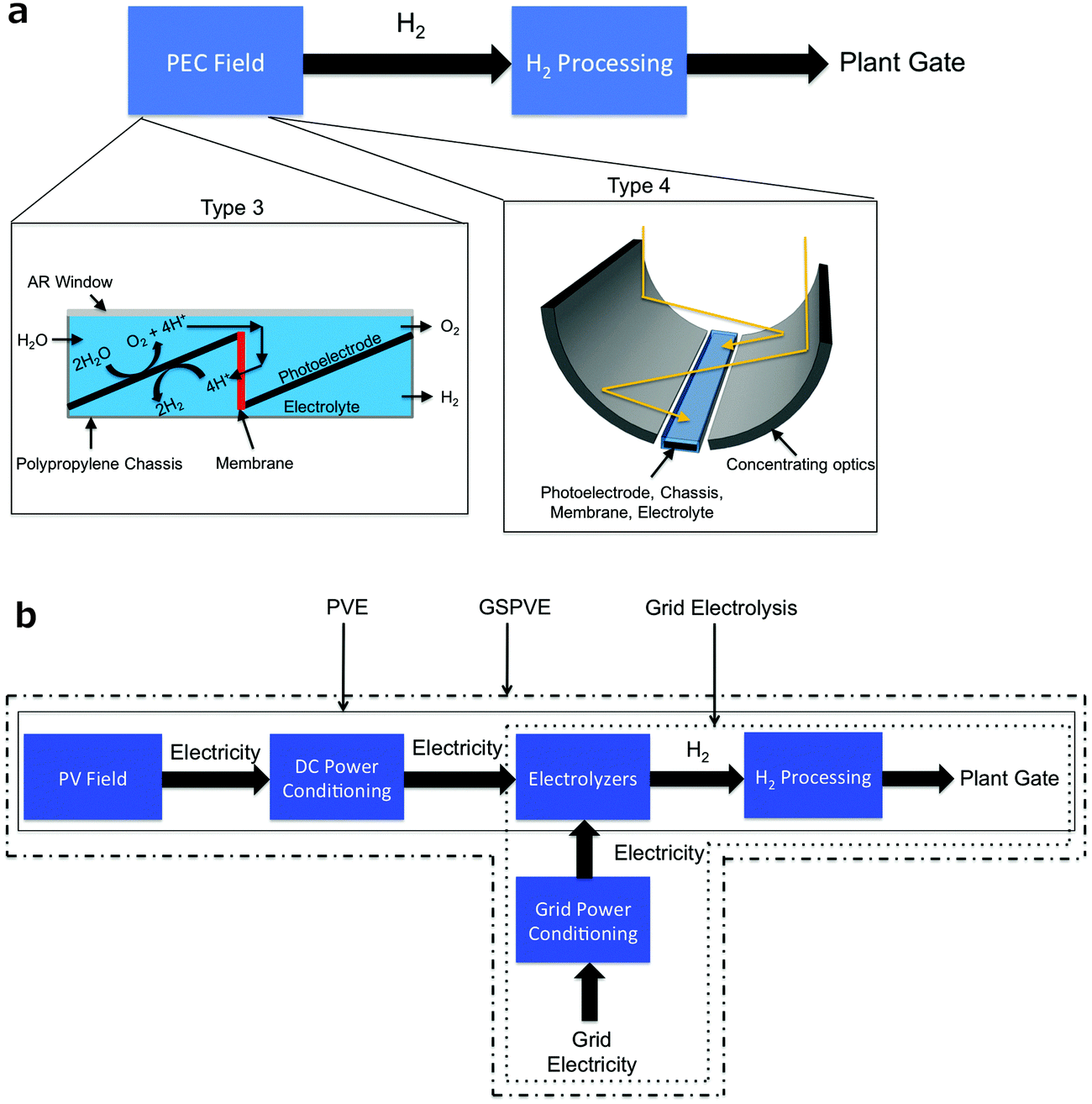 | ||
| Fig. 1 (a) Block diagram depicting the power flow through a PEC plant. The cell specifics for the Type 3 and 4 systems are shown in the insets. (b) Block diagram of the power flow through photovoltaic electrolysis (PV-E), grid assisted photovoltaic electrolysis (GSPV-E) and grid electrolysis plants. | ||
The next two systems considered herein consist of photovoltaic modules connected through DC power electronics to discrete electrolysis units. One system, referred to as PV-E, relies solely on solar energy for hydrogen production. In this system, the electrolyzers are connected to the photovoltaics with or without a DC–DC converter, and are sized to match the maximum output of the photovoltaics. The second system, referred to as GSPV-E, includes a grid connection and sized the electrolysis units based on their maximum capacity factor such that grid electricity supplements the photovoltaic electricity whenever the photovoltaic modules are not operating at their maximum capacity.
The last system, grid electrolysis, which served as a benchmark by which to measure the above four systems, is the predominant currently practiced technique for hydrogen production from electricity.
A final general scenario is mapped out over a range of capital expenses and STH full plant efficiency values, to demonstrate their relationship to the LCH, as well as to describe the performance and economic values that must be met for solar hydrogen to be economically competitive with existing and developing technologies.
Technoeconomic assumptions
All economic assumptions are based on values taken from the U.S. market. In general, material and equipment capital expenses are transferrable globally, but installation labor and other soft balance of system costs such as customer acquisition and permitting can be more location dependent. Weighted average capital costs for utility scale photovoltaic installations in 2013–2014 were ∼$2.3 Wp−1 in the U.S. with only Europe and China having lower costs at ∼$1.9 Wp−1 and ∼$1.6 Wp−1, respectively.18 Such differences are likely due to soft balance of systems cost differences as is the case for residential systems, but the magnitude of the differences is significantly smaller for utility-scale installation.19 These capital cost differences for utility-scale systems are roughly offset by the higher capacity factors in the U.S., suggesting that the conclusions discussed herein remain valid irrespective of the location dependent cost differences and are representative of the state-of-the-art costs globally.18| System specific technical parameters | |
|---|---|
| STH efficiency | 9.76% |
| Electrolyzer efficiency | 61% |
| Electrolyzer and PV capacity factor | 0.204 |
| Photovoltaic efficiency | 16% |
| Photovoltaic area (mS2) | 7.5 × 10⁵ m2 |
| Number of PEM stacks (500 kg day−1 stack−1) | 99 |
The base-case system STH efficiency was assumed to be 9.76%, which is the product of the photovoltaic module efficiency of 16% and the electrolyzer plant efficiency of 61%.13,21,22 Replacement expenses for the electrolyzer were assumed to be identical to that of the grid electrolysis system, whereas the photovoltaics were assumed to last the lifetime of the plant.13
| System specific technical parameters | |
|---|---|
| STH efficiency | 9.76% |
| Electrolyzer efficiency | 61% |
| Electrolyzer capacity factor | 0.97 |
| Photovoltaic efficiency | 16% |
| Photovoltaic area (mS2) | 1.8 × 10⁵ m2 |
| Number of PEM stacks (500 kg day−1 stack−1) | 21 |
| Capital expenses | |
|---|---|
| Component | 2014 $ mS−2 |
| Electrolyzer stack13 | 64 |
| Photovoltaic modules20 | 96 |
| Wiring21,22 | 16 |
| DC–DC converter | 51 |
| AC–DC rectifier13 | 30 |
| Other electrolyzer hard BoS13 | 61 |
| Panel mounting materials21,22 | 29 |
| Photovoltaic installation labor21,22 | 29 |
| Electrolyzer installation labor13 | 19 |
| Other soft BoS21,22 | 56 |
| Operating and maintenance expenses | |
| Electricity25 | $0.07 kWh−1 |
| System specific technical parameters | |
|---|---|
| STH efficiency | 9.76% |
| PEC Area (mS2) | 7.6 × 10⁵ m2 |
| Capital expenses | |
|---|---|
| Component | 2014 $ mS−2 |
| Window (AR coated glass)27 | 5 |
| Chassis (polypropylene)28 | 33 |
| Semiconductors (c-Si, 16% S-E)20,29 | 48 |
| Catalyst (Pt, IrOx)26 | 8 |
| Membrane (Nafion, 5 mil)30 | 50 |
| PEC cell assembly labor13 | 10 |
| Compressors (2 stage)14 | 16 |
| Water condenser14 | 0.3 |
| Heat exchangers14 | 0.4 |
| Piping (PVC)14 | 3.4 |
| Control systems14 | 5.4 |
| Panel mounting materials21,22 | 29 |
| Installation labor21,22 | 29 |
| Other BOS21,22 | 56 |
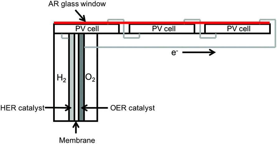 | ||
| Fig. 2 One possible architecture (not to scale) for a series connected side-by-side triple junction Si PV cell structure directly integrated into the chassis of an electrolysis unit designed for the Si device output. Such a structure would be a single unit that could be installed like a traditional PV panel, identical to the base case Type 3 design, with gas collection as opposed to electrical connections. | ||
Including the PEC chassis material, PEC module labor and AR coated glass window would result in a component similar to a PV module with costs (not including membrane or catalyst costs) of $96 m−2, identical to the PV module areal cost. Thus, any capital cost differences between the Type 3 and PV-E systems will be due to balance of system costs or any material differences for the electrolysis portion of the system.
This near-term demonstration system serves as a baseline for comparison with photoelectrochemical approaches on a technoeconomic basis. Platinum (Pt) and iridium oxide (IrOx) catalysts were assumed, a worst-case cost scenario because of the high spot prices for both materials. The $8 mS−2 cost of the catalyst for a specified solar collection area (mS2) is assumed to be identical to that of the PV-E system because state-of-the-art PEM electrolyzer catalyst loadings, ∼1 mg cm−2 of Pt (466 nm thick) and ∼2 mg cm−2 of IrO2 (1.7 μm thick)33 for 1–10 A cm−2 operating current density, correspond to similar total catalyst mass loadings as state-of-the-art photoelectrochemical catalyst loadings, 1–10 μg cm−2 (0.5–5 nm thick) of Pt and 2–20 μg cm−2 of IrO2 (1.7–17 nm thick) for 10 mA cm−2 of operating current density in a PEC system.26
A Nafion PEM was assumed to serve as the ionically conductive, gas impermeable membrane, with costs of $2000 kg−1 estimated based on current production volume prices for a 5 mil (127 μm) thick membrane.30 Based on the photoelectrochemical cell design, the membrane area required is 10% of the solar collection area.34 A polypropylene chassis having a 1 cm thickness and an area equal to the PEC area was assumed, with a raw material price of $1.5 per kg.28 The chassis was assumed to be manufactured via injection molding, where the raw materials cost is approximately 43% of the total manufactured chassis cost.35 The window was assumed to be made from high quality, anti-reflective glass used by the photovoltaic industry that is compatible with acidic media.27 Replacing the back of the polypropylene chassis with glass would decrease the materials cost of the PEC module. However, the cost differential is relatively small as compared to the total capital cost, and increases in handling related costs due to the different mechanical properties of glass versus polypropylene could nullify the material cost differential. If, however, a measurable difference in the base-case capital costs assumed herein exists, the impact of these differences on the LCH can be assessed using the analysis summarized below (in Fig. 10). These cell materials were assumed to be resistant to degradation by sunlight over the lifetime of the device, and any mechanical issues related to thermal mismatches between materials were assumed to be solved for the quoted costs of the base case. The photoelectrochemical module assembly labor was assumed to be equal to the electrolyzer assembly cost on a $ W−1 basis because both systems entail assembly of the chassis and active components (membrane electrode assembly for an electrolyzer and membrane and photoelectrode(s) for a PEC device).13 This is a reasonable estimate given publicly available data, but is likely an optimistic lower bound because the PEC system areal power density (W m−2) is roughly two orders of magnitude lower than the electrolyzers, requiring significantly larger areas of PEC components to be assembled and/or seamless integration of the materials to allow for fabrication integrally and/or with minimal labor.
The water delivery and gas collection, processing and control system costs were taken from previous work,14 but the compressors were assumed to provide a higher compression ratio of ∼5.5:1 versus 4.5:1 in the reference case evaluated previously. Polyvinyl chloride (PVC) piping was assumed in the base case due to the sufficiently low hydrogen permeability and embrittlement of PVC at the modest hydrogen collection pressures present in both PEC systems.26,36 These assumptions result in gas processing and water delivery unit costs ($ mS−2) that are roughly half the cost of the units used to perform the same tasks in the PV-E design. Confidence is higher on the PV-E hard BoS costs due to the commercial maturity of each of the individual systems, while the PEC system costs have only undergone a high-level engineering design because no known systems have received design certifications and permitting nor been constructed.14 Thus the potential for significant changes to the PEC system hard BoS costs exists, with the values assumed herein likely representing an optimistic cost scenario. The panel mounting materials, installation labor and other soft balance of systems (BoS) costs were taken directly from utility-scale photovoltaic panel installations on a $ mS−2 basis.21,22 The installation was assumed to be sited in areas that historically on a decade-scale have little chance of experiencing a hard freeze, specifically in plant hardiness zones 8 and above (i.e. where citrus trees are planted and thrive); consequently, additional costs associated with heating to avoid any liquid water from freezing were not included.37
The active components (semiconductors, catalyst, membrane) were assumed to be replaced every 7 years, based on expected component lifetimes from the electrolyzer industry, though no complete PEC cell that performs unassisted water splitting has yet been demonstrated to be stable for more than one week.13,17 The installation cost for replacement components was taken to be 15% of the component cost. All other components were assumed to need no replacement over the system lifetime. An annual operating and maintenance cost of 3.2% of the installed capital was taken from the PEM electrolyzer industry.13 All of the other components (DI water production, initial charge of acid or base, etc.) were not considered independently because previous studies have found these costs to be insignificant relative to the other capital and operating cost contributions.14,15
The plant efficiency was assumed to be identical to that of the PV-E system, 9.76%. This efficiency is consistent with a photovoltaic component efficiency of 16%, an electrolysis and electrochemical cell efficiency of 70% (1.75 V) and a gas collection and processing efficiency of 87%. A maximum practical PEC efficiency of 25% was estimated using the product of the maximum predicted efficiency of the PEC cell (28.7%, radiative recombination-limited photovoltaics and state-of-the-art catalysts)38 and a gas collection and processing efficiency of 87%.
| System specific technical parameters | |
|---|---|
| STH efficiency | 20% |
| Capacity factor | 0.186 |
| PEC area (mS2) | 3.7 × 10⁵ m2 |
| Capital expenses | |
|---|---|
| Component | 2014 $ mS−2 |
| Window (AR coated glass)27 | 0.5 |
| Chassis (polypropylene)28,35 | 6.6 |
| Semiconductors (InGaP/GaAs)39 | 175 |
| Catalyst (Pt, IrOx)26 | 8 |
| Membrane (Nafion, 5 mil)30 | 5 |
| Tracker hardware40 | 44.8 |
| Concentrators (parabolic)41 | 48 |
| Compressor (1 stage)14 | 14.5 |
| Water condenser14 | 0.2 |
| Heat exchanger14 | 0.4 |
| Piping (PVC)14 | 1.6 |
| Control systems14 | 8.9 |
| Panel mounting materials21,22 | 29 |
| Installation labor21,22 | 29 |
| Other BOS21,22 | 59 |
In this Type 4 base-case system, the assumed electrochemical compression to 10 atm reduces the required downstream compression to a single stage, with a single heat exchanger, relative to the two-stage compressor assumed in the base-case Type 3 system. Increased controls are needed in the base-case Type 4 system to handle the collection of pressurized gas from the PEC panels.14 All of the other component capital costs are identical to those for the Type 3 system, but the cost per unit of PEC area is different from the Type 3 base-case system due to the increased efficiency and thus decreased PEC area in the Type 4 base-case system. The components replaced and replacement period (7 years) and installation expense for the Type 4 base-case system are assumed to be identical to those assumed for the base-case Type 3 system.
The capacity factor for the Type 4 base-case system is lower than that assumed for the other systems, because it is assumed that the concentrators cannot collect diffuse sunlight (see ESI,† for calculation). The plant efficiency was assumed to be 20%, consistent with component efficiencies of 33% for the photovoltaic, 68% (1.8 V) for electrolysis and the electrochemical cell, and 90% for the gas collection and processing.
| System specific technical parameters | |
|---|---|
| Plant efficiency | 61% |
| Capacity factor | 0.97 |
| Number of PEM stacks (500 kg day−1 stack−1) | 21 |
| Capital expenses | |
|---|---|
| Component | 2014 $ W−1 |
| Electrolyzer stacks13 | 0.4 |
| Balance of systems13 | 0.57 |
| Installation (12% of un-installed capital)13 | 0.12 |
| Contingency factor (15% of un-installed capital)13 | 0.15 |
| Site preparation (18% of un-installed capital)13 | 0.18 |
| Operating and maintenance expenses | |
| Electricity25 | $0.07 kWh−1 |
Net present value (NPV) analysis
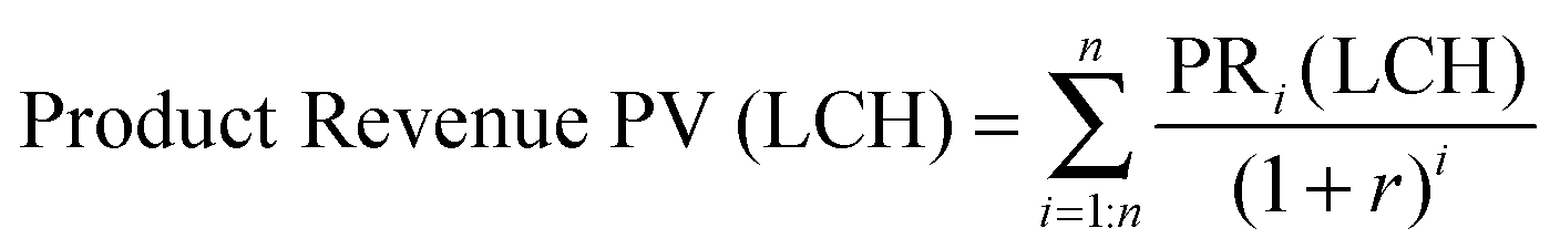
A standard discounted cash flow was applied to each technology and sensitivity case over the assumed plant lifetime. The capital expenditure was assumed to occur over a one-year construction period. All of the operating expenses and product revenues depend on the LCH and were discounted to the year of construction (eqn (1) and (2)). Replacement costs were included as operating expenses every 7th year. A pre-tax environment was assumed and thus depreciation was not applied to any capital assets. The LCH was calculated by adjusting its value such that the net present value of the capital and operating expenses and product revenue summed to zero (eqn (3)).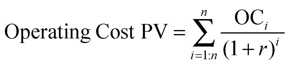 | (1) |
 | (2) |
| NPV = 0 = Product Revenue PV (LCH) − Operating Cost PV − Capital Expense | (3) |
Results
PV-E system
A combination of discrete photovoltaic and electrolyzer units is an important benchmark comparison to photoelectrochemical systems. PV and electrolyzer systems are commercial items with known costs. This combination can provide the highest solar-to-chemical conversion efficiency because each unit can be independently operated and optimized. Accordingly, the system efficiency is limited by the product of the independent photovoltaic and electrolyzer thermodynamic efficiency limits rather than the coupled PEC system thermodynamic efficiency limit.38,42Given the base-case capital and operating expenses, and the technical parameter assumptions, the LCH and total capital expense values for the base-case PV-E system were found to be $12.1 kg−1 and $260 MM ($371 mS−2), respectively. Fig. 3 displays the impact of the two most sensitive parameters, plant efficiency and active component capital expense per area of solar collection, mS−2, on the LCH of the base-case PV-E system. This analysis thus indicates that improving the plant efficiency has the largest impact on the LCH. Improved system efficiency could in principle be achieved through technological improvements in both the photovoltaic and electrolyzer units. For example, achieving the current photovoltaic cell record-efficiency, 46%,43 with all other parameters and capital expenses identical to the base-case system, results in LCH values of $9.4 kg−1 for the PV-E system. Decreases in the capital cost of the photovoltaic and/or electrolyzer units leads to diminishing returns because the hard and soft BoS costs remain, and constitute the dominant costs of an installed system.
 | ||
| Fig. 3 A contour plot of the LCH ($ kg−1) for the PV-E system as a function of the plant efficiency and active component (PV modules and electrolyzers) areal capital expense normalized by the required solar collection area ($ mS−2). The base-case result is indicated by the yellow circle. Contours are labeled at $2 kg−1 intervals. | ||
For a broader perspective, Fig. 4 illustrates the impact that the PV and electrolyzer subsystem costs have on the levelized cost of hydrogen. As an example, assume that PV systems can achieve a levelized cost of electricity (LCOE) value of $0.02 kWh1, which would require a capital cost of ∼$0.5 Wp−1 (assuming a 25 year lifetime, 10% discount rate, and 30% capacity factor). Fig. 4 demonstrates that at a PV subsystem cost of $0.5 Wp−1, a free electrolyzer would result in a levelized cost of hydrogen of $2.50 kg−1. This situation reflects the cost per joule of electricity at $0.02 kWh−1, converted directly into a cost per joule of H2, in conjunction with an electricity-to-H2 system conversion efficiency of 61%, with no cost for the conversion unit. To obtain a cost of $3 kg−1 of H2 with a PV capital cost of $0.5 Wp−1, the electrolyzer capital cost must be <$0.1 W−1, which is an order of magnitude lower than current electrolyzer capital costs. The development of a truly disruptive electrolysis technology is required to attain these costs, because electrolysis and the closely related chlor-alkali process have been practiced at scale for over a century. The current global chlor-alkali production of 60 million metric tons per year consumes ∼150 TW h of electricity annually, which is similar to the current worldwide annual solar electricity production of ∼280 TW h (178 GW installed, 18% capacity factor). These large reductions in capital costs are required due to the low capacity factor of solar electricity as well as the modest electrolysis efficiency.
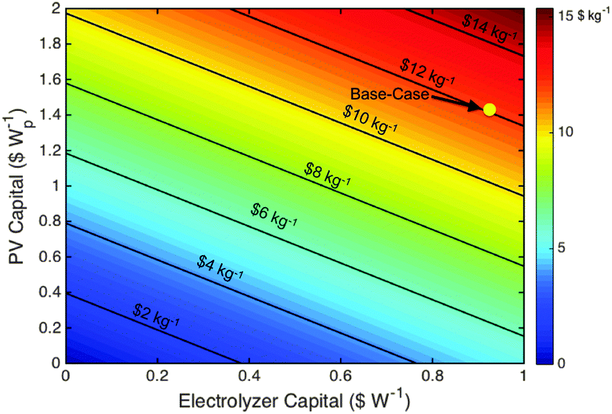 | ||
| Fig. 4 A contour plot of the LCH ($ kg−1) for the PV-E system as a function of the PV and electrolyzer subsystem capital expenses in $ W−1. The base-case result is indicated by the yellow circle. Contours are labeled at $2 kg−1 intervals. | ||
An alternative scenario could include a combination of photovoltaics and wind turbines to increase the capacity factor of the electrolyzers while maintaining 100% carbon free electricity. If electricity prices as low as $0.03 kWh−1 and an electrolyzer capacity factor of 75% could be achieved (to estimate an optimistic projected situation for large-scale PV and wind electricity combined, with no storage, as the sole electricity generation sources, and assuming negligible costs for any needed new transmission lines), the resultant LCH value is $3.8 kg−1 assuming all other base-case values are constant. To reach $3 kg−1 or $2 kg−1 would require electrolyzer capital cost reductions of 60% (to $0.6 W−1) or 80% (to $0.16 W−1), respectively. If, alternatively, the electrolyzer is free and the capacity factor remains at 75%, the electricity price required to achieve LCH values of $3 kg−1 and $2 kg−1 is $0.055 kWh1 or $0.037 kWh−1, respectively.
GSPV-E system
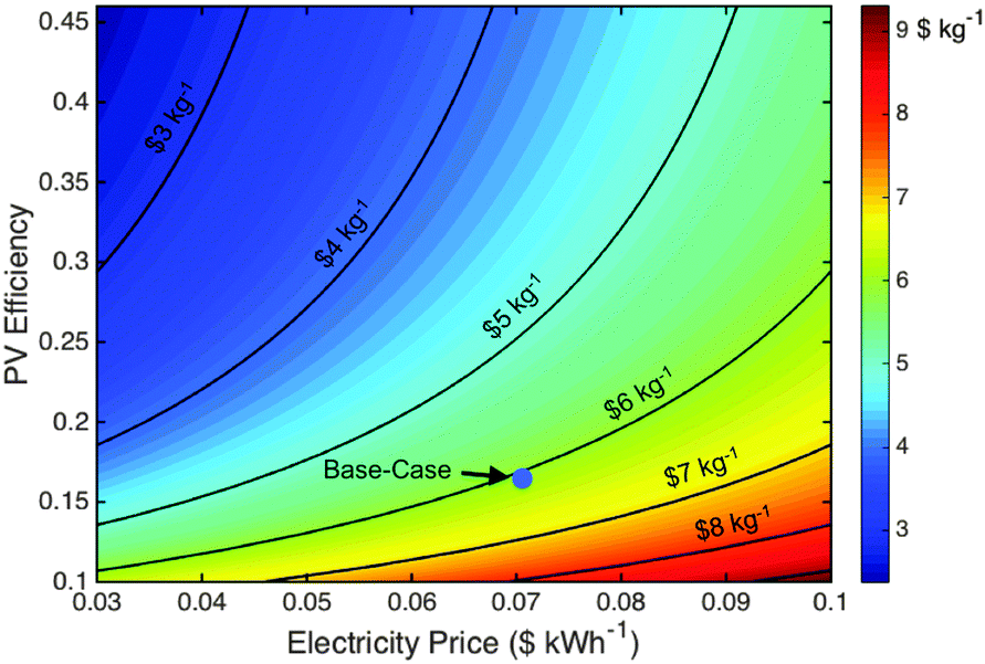
Capacity factors are critical to any commercial operation and comprise a fundamental limitation of terrestrial solar energy systems. Increases in the electrolyzer capacity factor can be obtained during non-peak solar hours and at night by supplementing the PV electricity with grid electricity. The GSPV-E system thus constitutes a hybrid of grid electrolysis and photovoltaic electrolysis systems, with ∼75% of the hydrogen produced by power supplied by grid electricity.The LCH and total capital expense values for the GSPV-E system are $6.1 kg−1 and $66 MM ($441 mS−2), respectively. Fig. 5 displays the impact of the two most sensitive parameters, the photovoltaic efficiency and the electricity price, on the LCH of the GSPV-E system. This analysis suggests that at high photovoltaic efficiencies, >∼25%, the electricity price has the largest impact on the LCH because the photovoltaic areal requirement, and thus capital cost, decreases with increasing efficiency. However, the photovoltaic efficiency becomes more impactful at values <∼25%, because of the increase in photovoltaic areal requirements. Achieving the current record-efficiency photovoltaic cells, 46%,43 within this device, assuming base-case capital expenses, results in LCH values of $5.6 kg−1 for the GSPV-E system. Such high module efficiency values have not yet been demonstrated and will require multi-junction architectures that can achieve cost metrics similar to Si on a $ W−1 basis.
 | ||
| Fig. 5 A contour plot of the LCH ($ kg−1) for the GSPV-E system as a function of the photovoltaic efficiency and electricity price ($ kWh−1). The base-case result is indicated by the blue circle. Contours are labeled at $1 kg−1 intervals. | ||
Grid electrolysis
Grid electrolysis using alkaline or proton-exchange membrane electrolyzers are mature, commercial technologies that are used herein as a benchmark. Prior studies have investigated the detailed costs of each component of a PEM electrolysis system and are used herein.13 However, the total capital cost of PEM and alkaline electrolysis facilities are similar, such that all conclusions based on the PEM systems apply approximately to alkaline systems as well. Supported by these previous studies, a high-level analysis was performed and resulted in a base-case LCH and capital cost for grid electrolysis of $5.5 kg−1 and $34 MM, respectively. Operating expenses, in the form of the cost of electricity, constituted the largest component of and sensitivity to the LCH, as has been shown previously.13Type 3 PEC system
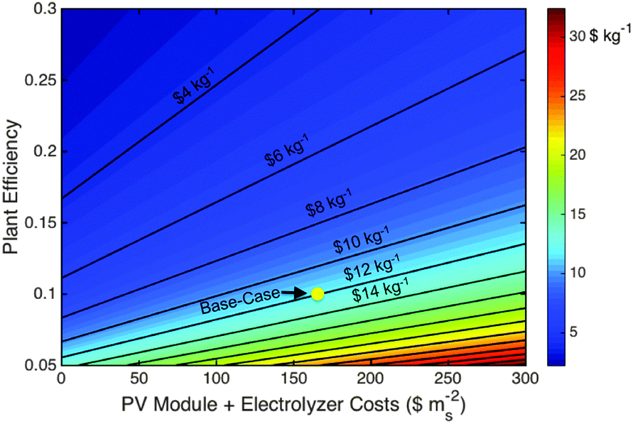
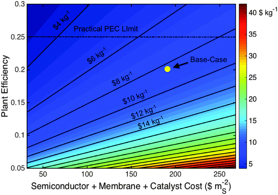
The Type 3 base-case LCH and capital cost values are $11.4 kg−1 and $205 MM ($293 mS−2), respectively, which are lower than the LCH for the comparable base-case PV-E systems. Relative to the base case, the PV-E system must exhibit an efficiency increase to 11.5%, or a decrease in the capital expense to $245 MM ($351 mS−2), to overcome this difference and reach cost parity with the base-case Type 3 PEC system.Fig. 6 demonstrates the impact of the two most sensitive parameters, plant efficiency and active component capital expenses, on the Type 3 system LCH value. Similar to the PV-E system, the efficiency has the largest impact on the LCH value, while decreases in the active component capital expenses have diminishing returns due to the continuing presence, and dominance, of the hard and soft BoS costs. Achieving a maximum practical plant efficiency of 25% at the base-case capital cost would result in a $5.1 kg−1 H2 LCH, while maintaining the base-case efficiency and reducing the photovoltaic stack, membrane and catalyst component costs to $0 mS−2, a non-practical value, would result in a ∼$6.1 kg−1 H2 LCH. Improvements in the efficiency of Type 3 systems can be achieved by focusing on the most optimal tandem junction band-gap pairs,38,42 optimizing the semiconductor material growth quality and electronic properties44,45 and improving the oxygen-evolution reaction efficiency through catalyst development. These advances must be achieved with cost effective materials and fabrication techniques to justify any resulting increase in efficiency relative to the assumed base-case system characteristics.
 | ||
| Fig. 6 A contour plot of the LCH ($ kg−1) for the Type 3 PEC system as a function of the plant efficiency and active component (semiconductor, membrane and catalyst) capital expense normalized by the required solar collection area ($ mS−2). The base-case result is indicated by the yellow circle. Contours are labeled at $2 kg−1 intervals and the practical efficiency limit for PEC systems is indicated assuming direct electrical connection between the semiconductor and catalyst components without additional power electronics. | ||
The Type 3 bill of materials (Table 4) indicates that the capital costs of the electrocatalysts constitute a minor contribution to the active material costs, and moreover, to the total capital cost of the Type 3 base-case system. Furthermore, the base-case catalyst costs assumed use the most expensive catalysts, platinum and iridium oxide; use of any other catalyst would only decrease the catalyst capital cost contribution. These findings are consistent with, and reinforce, a recently performed analysis that focused only on the active components of a generic PEC system. That study found that, for an optimized system, the catalyst capital costs of even the most expensive catalysts are insignificant compared to the capital costs of the semiconductors.46 This conclusion is also consistent with commercial PEM electrolyzer cost breakdowns, which indicate that the catalysts constitute <7% of the total capital cost of the system.26
Type 4 PEC system
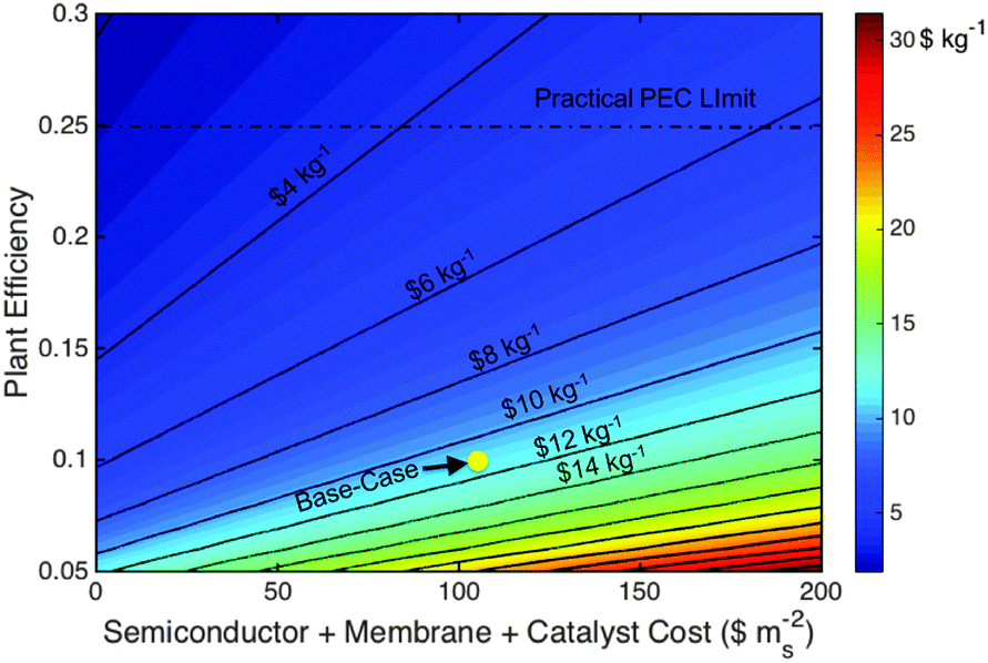
The Type 4 base-case LCH and capital cost values were $9.2 kg−1 and $160 MM ($428 mS−2), respectively, and are also lower than the LCH of the base-case PV-E system. The PV-E system must exhibit an efficiency of >16%, or must have a decrease in capital expense to $175 MM ($251 mS−2), to overcome this difference and reach cost parity with the base-case Type 4 PEC system.Fig. 7 demonstrates the impact of the two most sensitive parameters, plant efficiency and active component capital expenses, on the base-case Type 4 system LCH value. In contrast to the base-case PV-E and Type 3 PEC systems, the active component cost has the largest impact on the LCH value of the base-case Type 4 PEC system, mainly because of the current high cost and level of uncertainty in the component cost of the III–V high-efficiency photovoltaic materials. Achieving a maximum practical plant efficiency of 25% at the base-case capital cost would result in a LCH of ∼$7.4 kg−1 H2. In contrast, maintaining the base-case efficiency and reducing the capital cost to $283 mS−2, consistent with lowering photovoltaic component cost to $30 mS−2 or $0.1 Wp−1 at 30% photovoltaic efficiency, would result in a LCH of $5.2 kg−1 H2.
 | ||
| Fig. 7 A contour plot of the LCH ($ kg−1) for the Type 4 PEC system as a function of the plant efficiency and active component (semiconductor, membrane and catalyst) capital expense normalized by the required solar collection area ($ mS−2). The base-case result is indicated by the yellow circle. Contours are labeled at $2 kg−1 intervals and the practical efficiency limit for PEC systems is indicated assuming direct electrical connection between the semiconductor and catalyst components without additional power electronics. | ||
Type 3 PEC vs. PV-E system comparison
To support deployment at scale, PEC systems must be cost-advantaged relative to PV-E systems, because both systems provide identical functionality and energy quality. To understand the source of this difference in LCH, the capital expenses for each system were separated into active module, hard BoS and soft BoS capital expenses, according to the technical and economic assumptions associated with each base-case scenario. We note however that the PEC system technical hurdles of simultaneous stability, efficiency and operational safety that have challenged the field for 40+ years were assumed to be satisfied simultaneously in a single, large area system.Given these assumptions, Table 7 presents the discretized capital expenses for the PEC and PV-E systems, respectively. The difference in active component and soft BoS expenses between each system is relatively small, especially given the uncertainty in PEC active component expenses due to an absence of any commercial experience. The hard BoS costs demonstrate the largest difference with the PEC system estimated to be ∼2× lower than those of the PV-E system.
| PEC (ηSTH = 10%) | PV-E (ηSTH = 10%) | ||
|---|---|---|---|
| Active components | |||
| Membrane | 50 $ mS−2 | Electrolyzer stack | 65 $ mS−2 |
| Catalyst | 8 | Photovoltaic module | 96 |
| Semiconductor | 48 | ||
| Chassis | 38 | ||
| Assembly labor | 10 | ||
| Subtotal | 154 | Subtotal | 161 |
| Hard BoS | |||
| Gas processing | 20 $ mS−2 | Wiring | 16 $ mS−2 |
| Control systems | 6 | Other electrolyzer hard BoS | 61 |
| Panel mounting materials | 29 | Panel mounting materials | 29 |
| Subtotal | 55 | Subtotal | 106 |
| Soft BoS | |||
| Install labor | 29 $ mS−2 | PV install labor | 29 $ mS−2 |
| Other soft BoS | 56 | Electrolyzer install | 19 |
| Other soft BoS | 56 | ||
| Subtotal | 85 | Subtotal | 104 |
This difference is due to different modes of energy transmission within the PEC and PV-E plants as well as the fact that the PV-E system has two sets of hard BoS expenses, one for the photovoltaic and one for the electrolyzer units, while the PEC system has one set of hard BoS costs for its sole, integrated unit. In the PV-E system, electricity is the major energy carrier being transported from the photovoltaic modules to the electrolyzers (Fig. 1). However, in the PEC system, hydrogen is the energy carrier being transported from the modules to the gas processing systems and to the plant gate (Fig. 1). This difference indicates that transportation of hydrogen gas at low pressure, and subsequent compression of the H2, is less expensive per joule of energy transmitted than transportation and conditioning of relatively low power electricity. This result is consistent with capital expenses for high power transmission lines, in which electricity transmission expenses are ∼$1 MM (GW-mile)−147,48 as compared to hydrogen pipeline expenses of ∼$0.1 MM (GW-mile)−1.49,50 The LCH difference between both systems is relatively small, <$1 (kg H2)−1, and thus only a slight advantage lies with PEC systems.
Discussion
Summary of LCH and sensitivity results
Fig. 8 presents the base-case estimated LCH values for all systems analyzed herein. The LCH sensitivity to either system or photovoltaic efficiency, whichever is most appropriate, is also presented in Fig. 8, because efficiency has the greatest impact on LCH, by virtue of the areal dependencies of most of the component costs.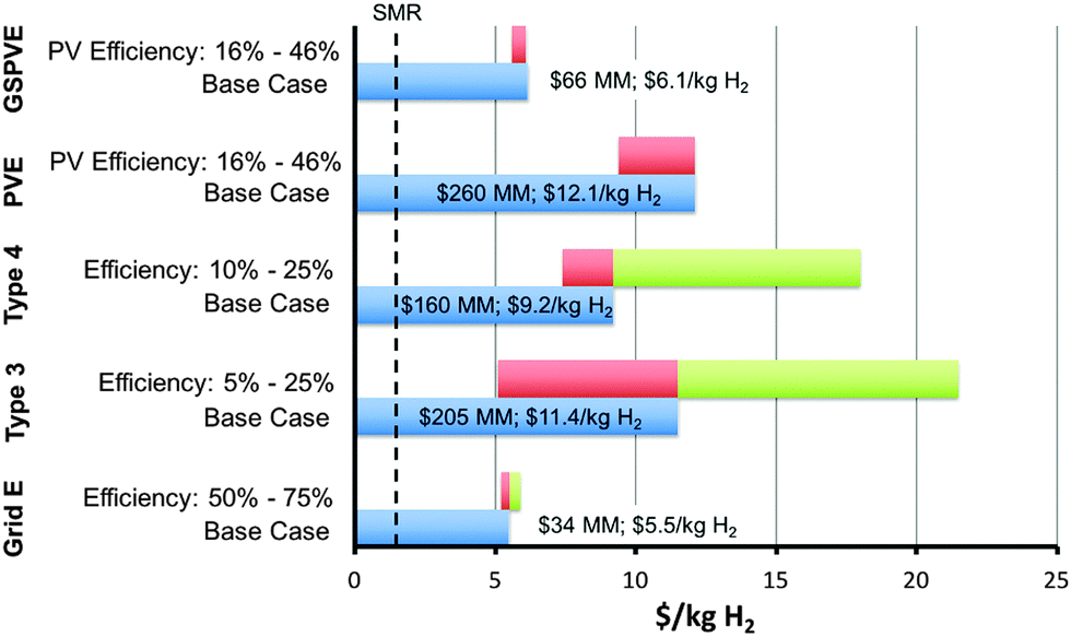 | ||
| Fig. 8 A summary of the base-case scenario results with the current and future predicted market hydrogen value without a CO2 tax indicated (dashed line, SMR current). | ||
Solar H2vs. fossil fuels
As compared to other, commercial, energy production and storage technologies, the solar-driven technologies analyzed herein are limited by an intrinsically diffuse solar power density of <1 kW m−2, as well as by a low capacity factor, of under 25%, for fixed-tilt panels in the optimal locations in the U.S. and by a conversion efficiency of under 20%. These limitations, combined with relatively high capital expenses, result in estimated untaxed levelized hydrogen production costs that are far larger than the cost of hydrogen derived from steam methane reforming (SMR) or grid electrolysis using electricity derived from fossil fuel. Accordingly, in an unconstrained CO2 energy market, solar electrolysis technologies based on the embodiments considered herein should not be expected to compete on a cost basis with fossil fuel-derived H2 for hydrocarbon upgrading or ammonia production. A CO2 tax of $1000 (ton CO2)−1, $800 (ton CO2)−1, $1200 (ton CO2)−1 and $450 (ton CO2)−1 would be required to increase the price of SMR to parity with the base-case Type 3 and Type 4 PEC, PV-E and GSPV-E (assuming CO2-free electricity) technologies, respectively.The difference between the grid electrolysis and solar hydrogen systems suggests that the effective price of solar electricity embedded within the PEC and PV-E systems is more than double the industrial average grid electricity price of $0.07 kWh−1. Similarly, at current electricity pricing, the use of solar electricity as only a fraction of the total electricity input, with the remainder of the input as grid electricity, while utilizing the electrolyzer unit at near its full capacity factor, resulted in a higher LCH than the sole use of grid electricity as the input. These findings thus both individually and collectively indicate that solar electricity has not reached grid parity, because the generally quoted solar electricity production costs do not include the cost of the fossil fuel back-up capacity required to provide the reliability required from, and achieved by, utilities. In contrast, the solar fuel plants analyzed herein could, in principle, provide the required high capacity factor and attendant grid reliability by themselves. Succinctly, even at comparable LCOEs, the value of electricity produced from an intermittent source such as sunlight is less than the value of electricity that can be dispatched with high reliability to meet demand.
Grid electrolysis vs. fossil fuels
The LCH for both grid electrolysis and fossil fuel reforming is dominated by operating expenses in the form of fuel costs. Current natural gas prices of ∼$3 (MM BTU)−1 result in a LCH of $1.39 kg−1 or $0.042 kWh−1 (33.3 kWh kg−1), which is less than the average “fuel” (industrial electricity) price in the U.S., $0.07 kWh−1.26 Natural gas prices would have to increase to $8.2 (MM BTU)−1 to reach parity with 100% efficient, zero capital cost grid electrolysis at the current average industrial electricity price. If the base-case grid electrolysis plant efficiency of 61% is assumed, the result is a natural gas parity point of $13.4 (MM BTU)−1. For comparison, liquefied natural gas (LNG) prices in Japan, where LNG prices have traditionally been highest worldwide, are currently <$8 (MM BTU)−1.51 Thus, H2 produced by grid electrolysis is more costly than H2 produced by SMR, as is evidenced by the current market dominance of SMR for hydrogen production.Grid electrolysis capital costs constitute 26% of the annual costs and are dominated by BoS costs, 59%, in comparison with 41% for the stack capital costs.13 The active catalyst and membrane component costs constitute <25% of the stack capital costs, suggesting that research on lowering these costs will provide small returns and thus the predominant efforts should be focused on cost-effective efficiency improvements.26 Predicted advances suggest an 18% decrease in LCH for future grid electrolysis systems, based on increased efficiency and decreased capital costs, though such advances still result in LCH values far higher than that of H2 produced by SMR.13 Hence, disruptive approaches to electrolysis, that can provide high efficiencies at very low costs compared to the current approaches, including those related to the chlor-alkai process that has been practiced at scale for over a century, constitute an important avenue for sustained research and development efforts.
Solar H2vs. low CO2 or CO2-neutral hydrogen production
Hydrogen is an essential chemical feedstock in fertilizer production and fossil fuel upgrading, with demand expected to continue for fertilizer production and possibly biomass upgrading even in a CO2-neutral economy. It is therefore important to assess different hydrogen production pathways and their economic competitiveness. Biomass reforming, CO2-free grid electrolysis, and SMR with carbon capture and storage (CCS) are alternative routes to low CO2 and CO2-neutral hydrogen production. Technoeconomic studies of biomass reforming and gasification have yielded estimated hydrogen production costs of <$3.0 kg−1 (adjusted to 2014 dollars).52,53 However, the LCH is highly dependent on the feedstock type as well as on production and transportation costs. Biomass energy production, in general, is geographically constrained to areas not in competition with food production. Given this constraint, estimates for the US and California suggest that only a small portion of the projected liquid fuel demand could be met by biomass.54,55 Dedicated use of biofuels for peaking capacity is possible, and given the enormous installed storage capacity of gas pipelines, power production by combustion of carbon-neutral biogas may provide a low-cost solution for some peaking applications.Nuclear fission reactors coupled with electrolyzers would produce hydrogen at $7.4 kg−1 using estimated nuclear electricity production costs of $0.1 kWh−1.56 This scenario of course explicitly assumes that the required nuclear fission power plants can overcome the financial and sociopolitical challenges such that sufficient numbers of plants are constructed and operated.
Natural gas- or coal-fired power plants with CCS constitute a low CO2 electricity technology at pilot-plant scale. The added cost of CCS to fossil-fuel-derived electricity is a subject of current debate, with predicted n-th plant electricity costs for natural gas plants estimated to be ∼$0.1 kWh−1, yielding a LCH of $7.4 kg−1 H2 for systems that are designed to have an ∼80% CO2 capture efficiency.56 However, this value assumes that the sequestration site exploration, and other currently large costs, as well as long-term technical and financial liability issues can be overcome.57 Alternatively, CCS directly integrated with steam methane reforming is expected to increase the cost of SMR-derived H2 by ∼$1 kg−1, to ∼$2.5 (kg H2)−1, given estimated CCS costs of ∼$100 (ton CO2)−1 and a SMR CO2 intensity of 10 ton CO2 per ton H2.
Solar H2vs. Low CO2 or CO2-neutral energy production and storage technologies
Two forms of energy consumption are considered here, electricity and transportation fuels. For low CO2 or CO2-neutral electricity production, nuclear fission and fossil fuels with CCS technologies will compete with wind and solar systems that incorporate storage in the form of batteries, fuels (H2), pumped hydro, compressed air or other energy storage technologies. As discussed above, nuclear fission and fossil fuels plus CCS have a mutually similar predicted electricity production price of ∼$0.1 kWh−1 assuming the challenges, also discussed above, for each of these technologies can be surmounted.Capital costs for fully installed battery systems are between $500 to $1000 kWh−1 or more per kWh of capacity.58 The levelized cost of storage, excluding input electricity costs, ranges from $0.25 kWh−1 to $0.49 kWh−1 for a capital cost range of $500 kWh−1 to $1000 kWh−1 (assuming a 10 year lifetime, one cycle per day, a 10% discount rate, 92% round-trip efficiency, and a linear decay to 80% of capacity at the end of life). To provide reliability commensurate with current base-load utility generation systems, battery systems coupled to wind or solar systems would need to be significantly oversized to accommodate resource availability extremes (days with little or no sunshine or wind), which would increase the battery storage costs further due to lower utilization rates than those assumed herein. The needs for research and development to develop new battery chemistries that could provide cost-effective grid-scale energy storage are widely recognized.
Conversion of hydrogen into electricity requires storage and an energy conversion process. Little information is available on real-world compression efficiencies for hydrogen storage, but the existing data suggest that compression from 14 bar to 430 bar, roughly equivalent to high pressure storage conditions, is 75% efficient.59 MW-scale fuel cell systems have efficiencies ranging from 40–49%.60–62 Including the efficiency losses only, with no inclusion of extra capital costs, the cost of electricity that results from hydrogen production costs of $11.4 kg−1 and $13.4 kg−1 H2, respectively, in conjunction with the above compression and fuel-cell conversion efficiencies, are $0.92 kWh−1 and $1.09 kWh−1, respectively. Because H2 storage is relatively inexpensive, the cost associated with extra storage capacity for overcoming resource availability extremes is expected to be less than the cost to achieve the same functionality using battery storage.59
Pumped hydroelectric and compressed air storage in suitable geologic formations are less expensive than batteries and hydrogen for energy storage applications, but the geologically constrained capacity limits may require other technologies to make up the needed balance of storage capacity, which can be a majority in a low-CO2 energy system that has a large amount of renewables in the generation mix.63 The total capacity required for future energy storage will depend upon the ultimate mix of generation capacity and demand.
The above analysis suggests that solar or wind systems that utilize current battery or fuel storage to obtain reliability metrics similar to that of current base-load or dispatchable load power plants have costs that are one order of magnitude higher than current electricity prices and than the expected prices of nuclear or fossil fuel with CCS alternatives. Within storage technologies for intermittent energy sources, the high cost of both battery and fuel storage options suggests that neither is clearly advantaged. Consequently, dramatic cost reductions are required to achieve competitiveness with other electricity technologies that can provide electricity on demand, providing a need for the development of disruptive technologies for cost-effective grid-scale energy storage.
A second possible market for solar hydrogen is transportation, in the form of fuel cell vehicles, where H2 is suited for use in light-duty vehicles as well as in some larger vehicles, such as buses. Hydrogen's relatively low volumetric energy density (4 MJ L−1 at 10000 psi), as compared to conventional aviation and diesel fuels (35 MJ L−1), provides, at present, a technical barrier to the use of high-pressure hydrogen fuel in these sectors.64 Significant improvements in hydrogen's stored volumetric system energy density, through hydrogen storage research, can make hydrogen suitable for markets that have fewer and/or more expensive technology alternatives.
In currently suitable markets, hydrogen will compete primarily with batteries. Land requirements may constrain biofuels to a relatively low maximum penetration level, even if solar hydrogen is used for biofuel upgrading. As discussed above, the costs of storage in the form of batteries or hydrogen are similar, yet high, thus neither has a clear advantage; both electric and fuel cell vehicles are available to consumers though in limited quantities. The recharge times of batteries also are limited due to resistive heating losses, providing a refueling advantage to hydrogen.
Comparisons to previous work
The findings presented herein are consistent with previous life-cycle analysis (LCA) studies.65 In particular, the energy-return on energy-invested (EROEI or EROI) for a large photoelectrochemical hydrogen production facility has been shown to be positive, with a maximum EROI value, based on any single parameter sensitivity, of <3:1, and a base-case EROI of 1.66. The minimum EROI (petroleum based) necessary to sustain the minimum standards of life is reported to be 3:1, but to sustain present standards of life in first-world countries the minimum EROI is generally higher, upwards of 14:1, for many of the luxuries we currently enjoy (health care, athletics, art, etc.).66 Current EROI values for petroleum are 20:1–30:1, and preferred new energy generation technologies would have similar EROI values, thereby allowing impoverished people to raise their standard of living to that of first-world countries.66 Both the economic and EROI assessments for base case solar hydrogen systems are an order of magnitude lower than currently competitive values. The broad agreement with the analysis presented herein grounds our results, future outlook, and suggested research avenues for solar electrolysis technologies. Specifically, such applications provide an opportunity for foundational research to contribute to the development of disruptive approaches to solar fuels generation systems that can offer higher performance at much lower costs than current embodiments of solar fuels generators.
Additionally, previous technoeconomic analyses have been performed on different solar hydrogen technologies, at different levels of depth. A 1998 report covering PEC and PV-E systems found LCH values similar to those calculated herein for their base-case systems.67 However, their predicted advancements in both PEC and electrolysis performance and economics have not yet been realized. Thus current costs, as presented herein, remain aligned with the base-case values in the previous report. That report suggested that PEC technologies could be advantaged over PV-E systems if the performance and economic goals set therein were met, but no quantitative argument was presented to determine the source of this advantage. In 2009, a comprehensive technoeconomic analysis focused solely on PEC systems.26 Many of the PEC plant economic assumptions made herein were taken directly from that report. LCH values for panel-based PEC systems therein were similar to the LCH values for the PEC systems evaluated herein (Type 3 and 4 systems), though their systems did not explicitly include the costs for a membrane, as is done herein. However, two other particle-based systems were studied therein and found to possess the potential for significantly reduced LCH values due to reduced balance of system costs. Finally a recent report that was focused on the PEC cell alone found that the catalyst cost contribution was negligible for even the most expensive electrocatalysts, Pt and Ir.46 This finding is consistent with the full technoeconomic analysis of both the components and installed system presented herein.
Direct solar CO2 reduction potential
Recent efforts have refocused attention on the direct electrochemical reduction of CO2, which has the possibility of making higher-value products that could potentially support a higher capital cost than can be supported by a hydrogen production process.The direct use of CO2 as an electrochemical reactant involves many chemical, engineering, and economic challenges due to the relatively low temperature and low electrode reaction rates, the absence of active and selective electrocatalysts, and the low concentration of CO2 in the atmosphere, the ultimate source for a closed-cycle sustainable CO2-based energy scenario. By necessity, a CO2-reduction system needs an inexpensive source of CO2 (as compared to the product value) delivered to the catalyst surface at a rate greater than the current density provided by the photovoltaic component (24 mA cm−2 for an ideal tandem junction device38 or equivalently  mol CO2 s−1 m−2). The low concentration of CO2 in air highly favors, and may require, capturing the atmospheric CO2 from a much larger area than is subtended by the solar capture area.68 Capturing CO2 from air is projected to cost more than $600 (ton CO2)−1, which eliminates many CO2 reduction products in an unconstrained energy market because their market prices, in $-(ton CO2)−1 equivalence, are less than $600 (ton CO2)−1 (Fig. 9).69,70 The products shown in Fig. 9 are species that have been measured and quantified during the electrocatalytic reduction of CO2 using copper electrodes.71 Additional routes include a two-step procedure consisting of an initial electrocatalytic step followed by a thermochemical step to produce ethylene glycol from CO2.72 Delivering CO2 in aqueous systems at a rate that is not limiting at 1 Sun solar fluxes requires a mass transport coefficient at least two orders of magnitude higher than is achievable for natural transport under optimistic conditions (high winds, limited by mass transport in the liquid phase) (see ESI,† for details).73 The concentrated CO2 sources and/or forced convection systems that are needed to overcome mass transport limitations will add cost to the overall system and product.
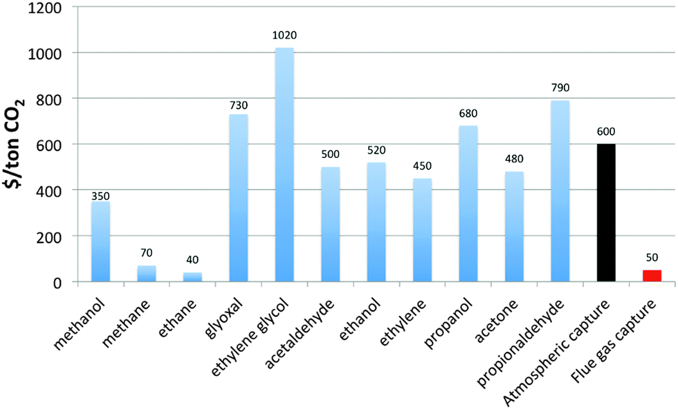 | ||
| Fig. 9 The cost of CO2 equivalence for a variety of known CO2 electrochemical reduction products on Cu. The conversion calculation assumed 100% utilization of CO2 and converted based on the mass of CO2 retained in the product molecule. The CO2 price of atmospheric capture (estimated) and state-of-the-art flue gas capture are shown for comparison. | ||
One concentrated CO2 source, shown in Fig. 9, is carbon capture from flue gas, with current state-of-the-art CO2 costs of $50 (ton CO2)−1.74 Product use in distributed applications would make the system a twice-thru carbon system that could serve to improve the efficiency of carbon utilization. The lower CO2 cost expands the possible reduction products from an economic perspective. These value-added products are used today for their chemical attributes and not as fuel sources, and all current fuels are more costly to produce by CO2 reduction than by current means even with CO2 at $50 (ton CO2)−1. Fig. 9 also provides information on the most value-added target products for near-term CO2 reduction approaches. Interestingly, an early-stage company, Liquid Light, focused on electrochemical CO2 reduction is targeting ethylene glycol production, likely in part due to the large spread at present between the reactant cost and the product value.72
Methanation of solar hydrogen with gas-phase CO2 may circumvent the mass transport issue that is a barrier to sustainable CO2 reduction in water. Other competing options for CO2 reduction include known commercial thermochemical processes including Fischer–Tropsch and intermediate methanol synthesis using Cu–ZnO catalysts. Irrespective of the pathway chosen the challenge of a relatively expensive reactant (CO2) remains. Further evaluation against the direct use of hydrogen is needed to understand these comparisons in more detail.
Guidance for research
Solar hydrogen production systems, which are at a laboratory research scale, have been compared herein to more mature technologies, because such systems are ultimately what solar hydrogen will compete against in the commercial arena. The base-case scenarios herein are representative of the best-case currently available PEC systems based on laboratory demonstrations, and are representative of current PV and electrolyzer systems. Our conclusions are based on these comparisons and identify the largest opportunities for achieving cost-competitive solar hydrogen production technologies.The results indicate that aggressive performance improvements and capital cost reductions are required simultaneously for solar hydrogen to achieve parity with fossil-fuel-derived hydrogen costs. Specifically, achieving a maximum practical plant efficiency of 25% at the base-case PEC costs is not sufficient to attain this goal. Fig. 10 illustrates this case and depicts the broader impact that changes in the total capital expense and plant efficiency can have on the LCH for generic PEC systems.
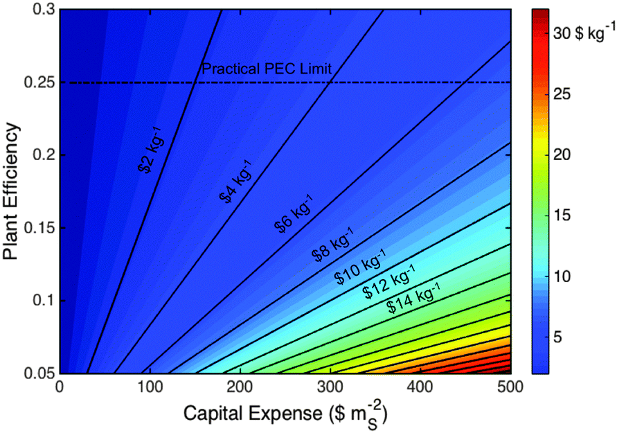 | ||
| Fig. 10 A contour plot of the LCH ($ kg−1) for a generic PEC system as a function of the plant efficiency and capital expense ($ mS−2). This calculation includes identical assumptions to the specific PEC analyses above, except that the replacement costs at 7 and 14 years are assumed to be 15% of the total capital expense. Contours are labeled at $2 kg−1 intervals and the practical efficiency limit for PEC systems is indicated assuming direct electrical connection between the semiconductor and catalyst components without additional power electronics. | ||
The maturity of the photovoltaic and electrolyzer industries, respectively, suggests that present balance of systems costs, combined with non-zero costs of the active components, will serve as barriers to constructing cost-effective solar hydrogen production facilities based on technologies that are cosmetically similar to current photovoltaic installations. Consequently, radically new plant-wide designs are needed, and the economics of such technologies should be validated through collaboration with chemical plant design engineers. For example, large-area installations of artificial turf, a relatively inexpensive robust outdoor material, cost ∼$110 mS−2.75 For such an installation ($110 mS−2) but comprised of photoactive solar hydrogen generating materials operating at the maximum practical efficiency of 25% having a plant lifetime of 20 years and active component lifetime of 7 years, the LCH would be ∼$1.8 kg−1 H2. This LCH is thus comparable to, but still somewhat higher than, current H2 derived from fossil fuels.
These metrics of 25% plant-wide STH efficiency and 7 year active component lifetime are similar to the 25% efficiency, 10-year electrode lifetime that comprise DOE targets for PEC hydrogen production, but are significantly higher than the 10% efficiency, 5-year particle lifetime in DOE targets for PEC hydrogen production using Type 1 and 2 baggie systems. The analysis herein suggests that irrespective of the active component architecture and cost, very high efficiencies are required, and thus all system efficiency targets should be ∼25% with active component lifetimes of 7–10 years.
PEC technologies may be advantaged because they may facilitate the implementation of such new plant designs. For example, the Type 1 and 2 designs (particles in low cost polymeric bags) entail a completely different form factor that is predicted to produce hydrogen at costs much closer to current market prices.14 Another potential design includes a flexible, membrane embedded device (using Si microwires for example) that could be rolled out like artificial turf with a hydrogen collection system similar to that used for landfill methane collection.76,77 The practicality of such designs should be rigorously analyzed to understand the potential advantages of each approach and thus to guide research and development trajectories and milestones.
Assuming such radically new designs are possible, the performance and cost of the active components remain to be demonstrated simultaneously. A consistent theme throughout the solar hydrogen technoeconomic analysis is that membrane and semiconductor costs are dominant while the semiconductor efficiency and stability are the limiting performance components. Accordingly, one conclusion is that electrocatalysts contribute little to the overall capital cost, and the performance of known electrocatalysts is sufficient to reach the needed performance targets in several possible implementations of the technology.46 The main area seen for potential impact is in acid-stable oxygen evolution catalysts, where iridium oxide is the only known material to exhibit satisfactory performance characteristics.78 However, Ir is the least abundant element in the Earth's crust, and the scarcity of Ir would preclude scaling the technology to terawatt levels of solar hydrogen capacity.79 Thus, acid stable oxygen evolution electrocatalysts that have a performance similar to that of iridium oxide would be required to achieve very high penetration scenarios using this particular electrolysis technology implementation.
Additionally, the limiting semiconductor component is the wide bandgap material in a tandem stack. Few materials exist with the proper bandgap, and of those that do, all are unstable under solar fuels operating conditions and are much too expensive due to growth methods that require epitaxy to achieve high performance. This later point has been a continual challenge for the photovoltaic industry where tunnel junction formation and lattice matching constraints substantially restrict materials compatibility. Concepts such as spectral splitting or multi-terminal electronic architectures could relax some of the challenges involved with materials growth, but introduce their own challenges that have, to date, been less attractive than traditional epitaxial growth solutions. Another potential solution is nanowire growth, which can relax lattice mismatch growth defects more readily than planar architectures, and thus may broaden the range of materials compatibility.
Membrane development is another important area because the membranes used in electrolyzers are too expensive for implementation in base-case solar fuels systems achitectures and moreover have higher ionic conductivities than needed for PEC devices.80 Thus, membranes designed specifically for PEC may enable lower costs due to different required performance targets in the associated technology implementation.
Device stability is critical to a cost-effective solar hydrogen technology. Protection of known high-efficiency semiconductors is likely the largest challenge. Improving recently developed protection and stabilization methods, and/or developing entirely new approaches that can protect square meters of semiconductor for years, while maintaining high efficiency, is needed to facilitate a viable, scalable solar hydrogen technology.81–83 In addition, typical stability measurements are performed with no standard protocol and generally under constant illumination; hence protocols should be developed to facilitate the intercomparison of results, and measurements should be extended to include dark conditions as well as the stresses associated with diurnal cycling for extended periods of time.
Summary and conclusions
Applied research based on firm scientific principles guided by realistic production and economic constraints is a foundation of societal progress. To have significant impact on the major problems of society, technological solutions must necessarily be competitive within the economic realities of the marketplace. Rigorous economic competitive analyses, applied after proof-of-concept research and development, can provide critical guidance on a project's further resource allocation, priorities and trajectory. This paradigm for applied research supports unrestricted scientific imagination along with foundational research, while providing an economic rationale to calibrate the intensity of additional human and financial capital for applied research.To this end, a comparative technoeconomic analysis of photoelectrochemical and photovoltaic-electrolytic solar hydrogen production systems was performed. The results indicate an estimated levelized cost of hydrogen (LCH) for base-case Type 3 and 4 photoelectrochemical systems of $11.4 kg−1 and $9.2 kg−1, respectively. For comparison, the estimated LCH for base-case PV-E and GSPV-E systems were $12.1 kg−1 and $6.1 kg−1, respectively. The base-case PEC systems are advantaged over the base-case PV-E systems because hydrogen transport from the panels to compression units is less expensive than electricity transport and conditioning from the PV panels to the electrolyzers.
Successful research and development, measured solely by achieving a system efficiency of greater than 20% within the current embodiments of solar H2 generators, is not sufficient to produce systems with LCH values comparable to the LCH of fossil-fuel derived electricity. Panel mounting materials, labor and other balance of systems costs, irrespective of the active materials, amount to LCH values in excess of current hydrogen and energy prices. For base-case PEC systems, a carbon tax of greater than $800 (ton CO2)−1 would be required in an unconstrained CO2 energy market for SMR to reach hydrogen price parity with these solar technologies.
Expected electricity prices from CO2-neutral nuclear and low-CO2 fossil fuel with CCS technologies are currently an order of magnitude lower than expected electricity prices from solar or wind systems with battery or fuel storage solutions that provide reliability similar to that of current base-load or dispatchable generation technologies. Given these low electricity prices, electrolytic hydrogen prices are also projected to be significantly lower than the solar hydrogen routes analyzed herein, requiring disruptive approaches to solar hydrogen generation relative to the present embodiments of the technology.
The capacity factor of presently known solar-based energy systems is their fundamental limitation; any capital item used only 20% or less of the day will be at a disadvantage to capital used more effectively. Efforts to increase the low capacity factor of terrestrial solar power systems, as well as re-designed solar installation schemes that significantly reduce the balance of system costs and increase the efficiency to near the Shockley–Queisser limit without increasing the capital cost, will have the largest impacts on the economic competitiveness of the resulting technology implementations. Radically new materials and system designs that achieve fully installed costs similar to simple material installations such as artificial grass are required to achieve the equally dramatic cost reductions needed for solar or wind power to compete with current generation technologies.
The reduction of CO2 directly to hydrocarbon fuels will require addressing important mass transport and inexpensive CO2 delivery challenges, which will require radically new and innovative solutions to push the technology forward. Any electrochemical process for CO2 reduction must be directly compared to the many well-known thermochemical processes for CO2 conversion that can be readily accomplished if hydrogen is available from either fossil fuel, nuclear fission, low-CO2-based electricity sources, or PEC-derived H2 production.
Acknowledgements
This material is based upon work performed by the Joint Center for Artificial Photosynthesis, a DOE Energy Innovation Hub, supported through the Office of Science of the U.S. Department of Energy under Award Number DE-SC0004993. Support for this technoeconomic analysis was provided jointly by the Dow Centre for Sustainable Engineering Innovation at the University of Queensland, and the Resnick Institute for Sustainability at Caltech.References
- A. Fujishima and K. Honda, Nature, 1972, 238, 37–38 CrossRef CAS PubMed.
- S. Dillich, T. Ramsden and M. Melaina, Hydrogen Production Cost Using Low-Cost Natural Gas, DOE Hydrogen and Fuel Cells Program, 2012 Search PubMed.
- V. Smil, Sci. Am., 2014, 52–57 Search PubMed.
- O. Khaselev and J. A. Turner, Science, 1998, 280, 425–427 CrossRef CAS PubMed.
- S. Licht, B. Wang, S. Mukerji, T. Soga, M. Umeno and H. Tributsch, J. Phys. Chem. B, 2000, 104, 8920–8924 CrossRef CAS.
- G. Peharz, F. Dimroth and U. Wittstadt, Int. J. Hydrogen Energy, 2007, 32, 3248–3252 CrossRef CAS.
- A. C. Nielander, M. R. Shaner, K. M. Papadantonakis, S. A. Francis and N. S. Lewis, Energy Environ. Sci., 2014, 8, 16–25 Search PubMed.
- L. Arriaga, W. Martinez, U. Cano and H. Blud, Int. J. Hydrogen Energy, 2007, 32, 2247–2252 CrossRef CAS.
- P. A. Lehman, C. E. Chamberlin, G. Pauletto and M. A. Rocheleau, Int. J. Hydrogen Energy, 1997, 22, 465–470 CrossRef CAS.
- P. C. Ghosh, B. Emonts, H. Janssen, J. Mergel and D. Stolten, Sol. Energy, 2003, 75, 469–478 CrossRef CAS.
- M. Bolinger and S. Weaver, Utility-Scale Solar 2013, Lawrence Berkeley National Laboratory, 2014 Search PubMed.
- G. Barbose, S. Weaver and N. Darghouth, Tracking the Sun VII, Lawrence Berkeley National Laboratory, 2014 Search PubMed.
- W. G. Colella, B. D. James and J. M. Moton, Hydrogen Pathways Analysis for Polymer Electrolyte Membrane (PEM) Electrolysis, Strategic Analysis Inc., 2014 Search PubMed.
- B. D. James, G. N. Baum, J. Perez and K. N. Baum, Technoeconomic Analysis of Photoelectrochemical (PEC) Hydrogen Production, Directed Technologies Inc., 2009 Search PubMed.
- B. A. Pinaud, J. D. Benck, L. C. Seitz, A. J. Forman, Z. Chen, T. G. Deutsch, B. D. James, K. N. Baum, G. N. Baum, S. Ardo, H. Wang, E. Miller and T. F. Jaramillo, Energy Environ. Sci., 2013, 6, 1983–2002 CAS.
- Capacity Factors for Utility Scale Generators Not Primarily Using Fossil Fuels, January 2008–July 2014, U.S. Energy Information Administration.
- K. Walczak, Y. Chen, C. Karp, J. W. Beeman, M. Shaner, J. Spurgeon, I. D. Sharp, X. Amashukeli, W. West, J. Jin, N. S. Lewis and C. Xiang, ChemSusChem, 2015, 8, 544–551 CrossRef CAS PubMed.
- Renewable Power Generation Costs in 2014, International Renewable Energy Agency, 2015.
- J. Seel, G. Barbose and R. Wiser, Why Are Residential PV Prices in Germany So Much Lower Than in the United States?, Lawrence Berkeley National Laboratory, 2013 Search PubMed.
- PV Spot Price, EnergyTrend, 2015.
- D. Feldman, R. Margolis and D. Boff, Q2/Q3 ‘14 Solar Industry Update, U.S. Department of Energy: SunShot, 2014 Search PubMed.
- T. Kimbis, C. Honeyman, N. Litvak, S. Kann, M. J. Shiao, S. Mehta, J. Jones, J. Baca, S. Rumery and A. Holm, Q2 2014 U.S. Solar Market Insight, Greentech Media Inc. and Solar Energy Industries Association, 2014 Search PubMed.
- B. Paul and J. Andrews, Int. J. Hydrogen Energy, 2008, 33, 490–498 CrossRef CAS.
- M. Zhou and Y. Liu, 2013 International Conference on Materials for Renewable Energy and Environment, 2014, pp. 52–56.
- Electricity Data Browser, U.S. Energy Information Administration.
- B. D. James, W. G. Colella and J. M. Moton, Techno-Economic Analysis of Hydrogen Production Pathways, Strategic Analysis Inc., 2013 Search PubMed.
- K. Melkonyan, Solar Glass Price Plunge to Cease as Trade Sanctions Take Effect, IHS Technology, 2014 Search PubMed.
- Platts Global Polypropylene (PP) Price Index, Platts.
- A. Goodrich, P. Hacke, Q. Wang, B. Sopori, R. Margolis, T. L. James and M. Woodhouse, Sol. Energy Mater. Sol. Cells, 2013, 114, 110–135 CrossRef CAS.
- C. Houchins, G. Kleen, J. Spendelow, J. Kopasz, D. Peterson, N. Garland, D. Ho, J. Marcinkoski, K. Martin, R. Tyler and D. Papageorgopoulos, Membranes, 2012, 2, 855–878 CrossRef CAS PubMed.
- C. R. Cox, J. Z. Lee, D. G. Nocera and T. Buonassisi, Proc. Natl. Acad. Sci. U. S. A., 2014, 111, 14057–14061 CrossRef CAS PubMed.
- T. J. Jacobsson, V. Fjallstrom, M. Sahlberg, M. Edoff and T. Edvinsson, Energy Environ. Sci., 2013, 6, 3676 CAS.
- M. Carmo, D. L. Fritz, J. Mergel and D. Stolten, Int. J. Hydrogen Energy, 2013, 38, 4901–4934 CrossRef CAS.
- S. Haussener, C. Xiang, J. M. Spurgeon, S. Ardo, N. S. Lewis and A. Z. Weber, Energy Environ. Sci., 2012, 5, 9922–9935 CAS.
- Injection Molded Plastics Market (Polypropylene, ABS, HDPE, Polystyrene) Analysis By Application (Packaging, Consumables and Electronics, Automotive, Building and Construction) And Segment Forecasts To 2020, Grand View Research, 2014.
- R. R. Barth, K. L. Simmons and C. S. Marchi, Polymers for Hydrogen Infrastructure and Vehicle Fuel Systems, Sandia National Laboratories, 2013 Search PubMed.
- USDA, Plant Hardiness Zone Map, 2015.
- S. Hu, C. Xiang, S. Haussener, A. D. Berger and N. S. Lewis, Energy Environ. Sci., 2013, 6, 2984–2993 CAS.
- M. Woodhouse and A. Goodrich, A Manufacturing Cost Analysis Relevant to Single- and Dual-Junction Photovoltaic Cells Fabricated with III-Vs and III-Vs Grown on, National Renewable Energy Laboratory, 2014 Search PubMed.
- S. Kann, M. J. Shiao, C. Honeyman, N. Litvak, J. Jones, L. Cooper, T. Kimbis, J. Baca, S. Rumery and A. Holm, U.S. Solar Market Insight, Greentech Media Inc. and Solar Energy Industries Association, 2015 Search PubMed.
- C. Turchi, Parabolic Trough Reference Plant for Cost Modeling with the Solar Advisor Model (SAM), National Renewable Energy Laboratory, 2010 Search PubMed.
- J. R. Bolton, S. J. Strickler and J. S. Connolly, Nature, 1985, 316, 495–500 CrossRef CAS.
- NREL, Best Research-Cell Efficiencies, 2015.
- T. G. Deutsch and J. A. Turner, Semiconductor Materials for Photoelectrolysis, 2014 Search PubMed.
- T. J. Grassman, J. Carlin, C. Ratcliff, D. J. Chmielewski, S. A. Ringel, Photovoltaic Specialists Conference (PVSC), 2013, pp. 149–153.
- C. A. Rodriguez, M. A. Modestino, D. Psaltis and C. Moser, Energy Environ. Sci., 2014, 7, 3828–3835 CAS.
- R. Pletka, J. Khangura, A. Rawlins, E. Waldren and D. Wilson, Capital Costs for Transmission and Substations, Western Electricity Coordinating Council, 2014 Search PubMed.
- Edison Electric Institute, Transmission Projects: At A Glance, 2013.
- W. Leighty, J. Holloway, R. Merer, B. Somerday, C. San Marchi, G. Keith and D. White, Compressorless hydrogen transmission pipelines deliver large-scale stranded renewable energy at competitive cost, Lyon, 2006 Search PubMed.
- S. Baufumé, F. Grüger, T. Grube, D. Krieg, J. Linssen, M. Weber, J.-F. Hake and D. Stolten, Int. J. Hydrogen Energy, 2013, 38, 3813–3829 CrossRef.
- Trend of the price of spot-LNG, Japanese Ministry of Economy, Trade and Industry, 2015.
- P. Spath, A. Aden, T. Eggeman, M. Ringer, B. Wallace and J. Jechura, Biomass to Hydrogen Production Detailed Design and Economics Utilizing the Battelle Columbus Laboratory Indirectly-Heated Gasifier, National Renewable Energy Laboratory, 2005 Search PubMed.
- C. E. G. Padro and V. Putsche, Survey of the Economics of Hydrogen Technologies, National Renewable Energy Laboratory, 1999 Search PubMed.
- J. C. S. Long, California's Energy Future: The View to 2050, California Council on Science and Technology, 2011 Search PubMed.
- J. Reilly and S. Paltsev, MIT Joint Program on the Science and Policy of Global Change, MIT Joint Program on the Science and Policy of Global Change, 2007 Search PubMed.
- Levelized Cost and Levelized Avoided Cost of New Generation Resources in the Annual Energy Outlook 2014, U.S. Energy Information Administration, 2014.
- A. J. Garnet, C. R. Greig and M. Oettinger, ZeroGen IGCC with CCS, The University of Queensland, 2014 Search PubMed.
- D. M. Rastler, Electricity Energy Storage Technology Options, Electric Power Research Institute, 2011 Search PubMed.
- G. Parks, R. Boyd, J. Cornish and R. Remick, Hydrogen Station Compression, Storage, and Dispensing Technical Status and Costs: Systems Integration, NREL, 2014 Search PubMed.
- FuelCell Energy, 1.4 Megawatts DCF1500 Specifications Sheet, FuelCell Energy, 2013.
- Ballard, CLEARgen Specifications Sheet, Ballard, 2014.
- Hydrogenics, Fuel Cell Megawatt Power Generation Platform, Hydrogenics, 2014.
- D. Steward, G. Saur, M. Penev and T. Ramsden, Lifecycle Cost Analysis of Hydrogen Versus Other Technologies for Electrical Energy Storage, National Renewable Energy Laboratory, 2009 Search PubMed.
- C. Yang, J. Ogden, D. Sperling and R. Hwang, California's Energy Future: Transportation Energy Use in California, California Council on Science and Technology, 2011 Search PubMed.
- R. Sathre, C. D. Scown, W. R. Morrow, J. C. Stevens, I. D. Sharp, J. W. Ager, K. Walczak, F. A. Houle and J. B. Greenblatt, Energy Environ. Sci., 2014, 7, 3264–3278 CAS.
- C. A. S. Hall, S. Balogh and D. J. R. Murphy, Energies, 2009, 2, 25–47 CrossRef.
- M. K. Mann, P. L. Spath and W. A. Amos, Technoeconomic Analysis of Different Options for the Production of Hydrogen from Sunlight, Wind and Biomass, 1999 Search PubMed.
- Y. Chen, N. S. Lewis and C. Xiang, Energy Environ. Sci., 2015, 8, 3663–3674 CAS.
- R. Socolow, M. Desmond, R. Aines, J. Blackstock, O. Bolland, T. Kaarsberg, N. S. Lewis, M. Mazzotti, A. Pfeffer, K. Sawyer, J. Siiola, B. Smit and J. Wilcox, Direct Air Capture of CO2 with Chemicals, American Physical Society, 2011 Search PubMed.
- K. Z. House, A. C. Baclig, M. Ranjan, E. A. van Nierop, J. Wilcox and H. J. Herzog, Proc. Natl. Acad. Sci. U. S. A., 2011, 108, 20428–20433 CrossRef CAS PubMed.
- K. P. Kuhl, E. R. Cave, D. N. Abram and T. F. Jaramillo, Energy Environ. Sci., 2012, 5, 7050 CAS.
- M. S. Reisch, Chem. Eng. News, 2015, 93, 15 Search PubMed.
- H. Herzog, Assessing the Feasibility of Capturing CO2 from the Air, MIT Laboratory for Energy and the Environment, 2003 Search PubMed.
- J. Davison, Energy, 2007, 32, 1163–1176 CrossRef CAS.
- Cost Analysis, http://www.fieldturf.com/en/fieldturf-difference/cost-analysis.
- J. M. Spurgeon, S. W. Boettcher, M. D. Kelzenberg, B. S. Brunschwig, H. A. Atwater and N. S. Lewis, Adv. Mater., 2010, 22, 3277–3281 CrossRef CAS PubMed.
- M. R. Shaner, K. T. Fountaine, S. Ardo, R. H. Coridan, H. A. Atwater and N. S. Lewis, Energy Environ. Sci., 2014, 7, 779–790 CAS.
- C. C. L. McCrory, S. Jung, I. M. Ferrer, S. M. Chatman, J. C. Peters and T. F. Jaramillo, J. Am. Chem. Soc., 2015, 137, 4347–4357 CrossRef CAS PubMed.
- Y. Chen, K. Sun, H. Audesirk, C. Xiang and N. S. Lewis, Energy Environ. Sci., 2015, 8, 1736–1747 CAS.
- A. Berger, R. A. Segalman and J. Newman, Energy Environ. Sci., 2014, 7, 1468–1476 CAS.
- S. Hu, M. R. Shaner, J. A. Beardslee, M. Lichterman, B. S. Brunschwig and N. S. Lewis, Science, 2014, 344, 1005–1009 CrossRef CAS PubMed.
- B. Seger, T. Pedersen, A. B. Laursen, P. C. K. Vesborg, O. Hansen and I. Chorkendorff, J. Am. Chem. Soc., 2013, 135, 1057–1064 CrossRef CAS PubMed.
- Y. W. Chen, J. D. Prange, S. Dühnen, Y. Park, M. Gunji, C. E. Chidsey and P. C. McIntyre, Nat. Mater., 2011, 10, 539–544 CrossRef CAS PubMed.
Footnote |
| † Electronic supplementary information (ESI) available. See DOI: 10.1039/c5ee02573g |
| This journal is © The Royal Society of Chemistry 2016 |