
 Open Access Article
 This Open Access Article is licensed under a
 Creative Commons Attribution 3.0 Unported Licence
Dye-sensitised semiconductors modified with molecular catalysts for light-driven H2 production
Janina
Willkomm
a,
Katherine L.
Orchard
a,
Anna
Reynal
*b,
Ernest
Pastor
c,
James R.
Durrant
c and
Erwin
Reisner
*a
aChristian Doppler Laboratory for Sustainable SynGas Chemistry, Department of Chemistry, University of Cambridge, Lensfield Road, Cambridge, CB2 1EW, UK. E-mail: reisner@ch.cam.ac.uk; Web: http://www-reisner.ch.cam.ac.uk/
bSchool of Chemistry, Newcastle University, Edward's walk, Newcastle Upon Tyne, NE1 7RU, UK. E-mail: anna.reynal@newcastle.ac.uk
cDepartment of Chemistry, Imperial College London, Exhibition Road, London SW7 2AZ, UK
First published on 19th November 2015
Abstract
The development of synthetic systems for the conversion of solar energy into chemical fuels is a research goal that continues to attract growing interest owing to its potential to provide renewable and storable energy in the form of a ‘solar fuel’. Dye-sensitised photocatalysis (DSP) with molecular catalysts is a relatively new approach to convert sunlight into a fuel such as H2 and is based on the self-assembly of a molecular dye and electrocatalyst on a semiconductor nanoparticle. DSP systems combine advantages of both homogenous and heterogeneous photocatalysis, with the molecular components providing an excellent platform for tuning activity and understanding performance at defined catalytic sites, whereas the semiconductor bridge ensures favourable multi-electron transfer kinetics between the dye and the fuel-forming electrocatalyst. In this tutorial review, strategies and challenges for the assembly of functional molecular DSP systems and experimental techniques for their evaluation are explained. Current understanding of the factors governing electron transfer across inorganic-molecular interfaces is described and future directions and challenges for this field are outlined.
 Left to right: Katherine L. Orchard, Janina Willkomm and Erwin Reisner |
Katherine L. Orchard obtained her PhD in chemistry at Imperial College London under the supervision of Prof. Charlotte Williams and Prof. Milo Shaffer, where she worked on nanomaterials synthesis. She spent two years in industry developing quantum dots for display technologies before joining the group of Dr Reisner as a Cambridge-AIMR Joint Research Centre Scientist to work on nanomaterial/molecular catalyst hybrid photocatalysts and photoelectrodes. Janina Willkomm obtained her master's degree in chemistry at the Leibniz University in Hanover under supervision of Prof. Peter Behrens, working on graphite oxide composite materials. She joined the group of Dr Reisner in 2013 as a PhD student in the Christian Doppler Laboratory for Sustainable SynGas Chemistry. Her research focuses on molecular H2 evolution catalysts and their integration with semiconducting materials to assemble hybrid systems. Erwin Reisner is a University Reader at the University of Cambridge, where he is also a Fellow of St. John's College and the head of the Christian Doppler Laboratory for Sustainable SynGas Chemistry. His group develops artificial photosynthetic systems by combining chemical biology, synthetic chemistry and materials chemistry. |
 Anna Reynal |
Anna Reynal obtained her PhD in nanoscience and nanotechnology at the Institute of Chemical Research of Catalonia (ICIQ). Her work, supervised by Dr Emilio Palomares, was focused on the development of dye-sensitised solar cells. She then joined Prof. James Durrant's group (Imperial College London), to study the kinetics of hybrid photocatalytic systems for proton and CO2 reduction. She is now a teaching fellow at Newcastle University, and her research focuses on studying the photocatalytic activity of solar-to-fuel conversion systems. |
 Left to right: Ernest Pastor and James R. Durrant |
Ernest Pastor obtained his degree in Chemistry at the University of Valencia. He then joined the group of Prof. James Durrant in 2012 at Imperial College London as a PhD student. His work focuses on the characterisation of materials for solar energy conversion using various electrochemical and laser spectroscopic techniques. James R. Durrant is Professor of photochemistry in the Department of Chemistry at Imperial College London and is leading the Ser Cymru Solar Initiative at Swansea University. His PhD, supervised by Prof. Lord Porter and Prof. James Barber (Royal Institution), was focused on studying the primary processes of natural photosynthesis. Since then, his research has focused upon chemical approaches for solar energy conversion into electricity (photovoltaics) or molecular fuels. He currently holds an ERC advanced grant and his research has recently been awarded with the Tilden Prize by the Royal Society of Chemistry (2012). |
Key learning points(1) Key principles of DSP operation in comparison with dye-sensitised solar cells and natural photosynthesis(2) Rational design principles for self-assembly of molecular dyes and catalysts on semiconductor nanoparticles (3) Methods for assembling and evaluating DSP systems, including bulk performance and spectroscopic techniques (4) Applications and current understanding of state-of-the-art DSP (5) Outlook into future developments of DSP |
1. Introduction
The development of new materials and devices capable of providing non-fossil derived fuels on a worldwide scale is key to ensuring the future sustainability and security of global energy supplies. Of all the available renewable primary energy sources, sunlight is by far the most abundant and the development of systems capable of its capture, conversion and storage remains the most promising means to meet global energy demands. While solar energy to electricity conversion has seen great progress in recent decades, direct conversion of this energy to chemical bonds tackles the challenges of energy storage and transport as well as providing a direct source of renewable fuel for use in established fuel-based technologies.1Hydrogen is a strong candidate for a renewable energy economy since it is a clean burning and energy dense fuel, as well as an important reagent for the chemical industry. Whereas the current primary H2 production process by steam reformation is highly energy intensive and uses fossil sources, solar-driven electrolysis of water would generate H2 from inexhaustible resources.1 Furthermore, extension of the water-splitting process to include CO2 reduction could open up the possibility of a sustainable economy by generating renewable carbon-based molecules that could be used as fuels or chemical feedstocks.2
Solar water splitting systems use electrons and holes photogenerated by a light-absorber to drive the water oxidation and proton reduction half-reactions at electrocatalyst sites. While many semiconductors and some molecular complexes are capable of acting as both light-absorber and catalyst,3 the majority of the systems reported are multi-component, coupling a light-absorber with a separate electrocatalyst in the form of a metal complex, an enzyme, or inorganic (nano)particles. The two halves of the reaction are often studied separately, with sacrificial electron donors or acceptors closing the catalytic cycle; however, practical devices without sacrificial agents will ultimately be required to carry out full water splitting. Several device design strategies for achieving full water splitting have been proposed, including solar cell-driven electrolysis (PV-electrolysers), coupling of complementary photoelectrodes in a photoelectrochemical cell (PEC cell),4 and chemically coupling two photocatalysts to form Z-scheme suspension systems.5
Photocatalytic systems based on molecular catalysts have been reported for both water oxidation and proton reduction.6 We focus herein on proton photo-reduction systems, which can be broadly divided into two categories: all-molecular (homogeneous) or semiconductor-based (heterogeneous; Fig. 1). In both, electron transfer (ET) from the photosensitiser to the catalyst can be achieved either directly or via a mediator (2M/2M−; e.g. methyl viologen) by simple mixing of components in solution; however, these approaches are inherently mass transfer (MT) limited.7 Linking the two components together through a covalent bond or another surface interaction (e.g. on a semiconductor) greatly enhances the rate of charge transfer by both increasing the effective local concentration of the components and by creating orbital overlap to facilitate electronic communication between the two species.
 | ||
| Fig. 1 Schematic representation of approaches to photocatalytic H2 evolution, demonstrating electron transfer (ET) routes between a light-absorbing dye or semiconductor (SC) and an electrocatalyst (cat): direct ET between the two components, mediated ET by a redox pair (2M/2M−), or direct ET when linked together. Without connection, ET is mass transfer (MT) limited, whereas introduction of a linkage greatly enhances the electronic connection. Reduction of the oxidised dye or valence band holes at the semiconductor following H2 evolution closes the redox cycle. Dye-sensitised photocatalysis (DSP) bridges traditional homogenous and heterogeneous catalysis. | ||
In this tutorial review, we focus on the emerging approach of dye-sensitised photocatalysis (DSP, Fig. 1). DSP bridges the fields of molecular and materials chemistry by coupling a molecular dye and catalyst through their co-adsorption onto a semiconducting particle, using the particle as both a scaffold and as a solid-state electron mediator. Taking inspiration from dye-sensitised solar cells (DSCs), such systems combine the capacity of semiconductors to accumulate and transport multiple charge carriers with the facile tuning of the system's optical properties by transferring the light absorption function to an interchangeable molecular dye. The immobilisation of dyes and catalysts onto a semiconductor surface can also allow the use of water insoluble molecules in aqueous media. DSP systems are synthetically facile to construct by directed and rational self-assembly in solution, leading to a ‘mix and match’ approach, whereby each component can be optimised individually, and the overall activity of the system is highly tuneable. However, to date, the efficiencies of such hybrid systems have been relatively low in comparison to their individual components.8 In order to advance this promising field, it is of importance to understand the interfacial interactions and ET processes occurring between the components. Here we aim to provide an introduction to the field of DSP, by first discussing the thermodynamic and kinetic requirements and design principles for such systems, followed by a discussion of DSP self-assembly, characterisation, and the evaluation of performance of such systems for solar fuel generation.
2. DSP systems
2.1 From ‘solar-to-electricity’ to ‘solar-to-fuels’
The basic concept of integrating molecular dyes with a semiconducting material is well-established in DSC technology for the conversion of sunlight into electricity. In a typical DSC setup (Fig. 2a and b), photogenerated electrons are collected at a TiO2 photoanode and holes are collected by the reduced species of a redox mediator (M/M−), which is then re-generated at the cathode to close the redox cycle. The key component of this type of solar cell is the efficient absorption of sunlight by the dye and the almost quantitative electron injection into the conduction band (CB) of the semiconductor.9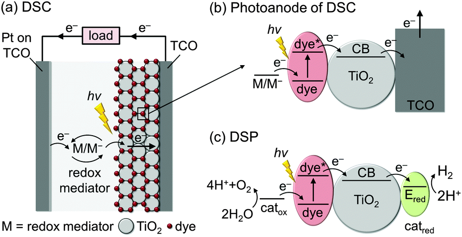 | ||
| Fig. 2 Schematic representation of (a and b) dye-sensitised solar cells (DSCs) for solar-to-electricity conversion and (c) concept of dye-sensitised photocatalysis (DSP) for full water splitting. TCO = transparent conducting oxide on glass; catox = water oxidation catalyst, catred = H2 evolution catalyst, M/M− = redox mediator. | ||
DSP builds upon the excellent dye-semiconductor interface, but electrons are transferred to an electrocatalyst for fuel production instead of generating electricity (Fig. 2c). Electrons from the photoexcited dye are transferred to a H2 evolution catalyst (catred) via the conduction band of TiO2, while the oxidised dye should be regenerated (directly or indirectly) by a water oxidation catalyst (catox) to close the fuel-making cycle.
Although DSC and DSP are conceptually similar, their requirements and operational challenges are markedly different. In order to carry out water splitting, it is necessary for DSP to function in water, whereas most DSCs operate in organic solvents and are damaged by moisture. The transition from organic to aqueous electrolyte solution is non-trivial, with issues arising from operational stability and changes at the interface between the DSP components.
From an energetic perspective, DSC operation requires the energy levels of the photoexcited dye to be suitably placed with respect to the CB of the semiconductor and the redox potential of the mediator to drive electron transfer and to generate a current. This aspect is more challenging in DSP, where the thermodynamics of the water oxidation and proton reduction reactions must also be taken into account. This places upper and lower limits on the absolute energy levels of light-absorbers and mediators: for proton reduction for example, the CB of the semiconductor must be more reducing than the thermodynamic proton reduction potential (E° < 0 V vs. the reversible hydrogen electrode, RHE).
Critically, catalysis in DSP is kinetically much more challenging than electron transfer (ET) and transport in DSCs. Whereas photovoltaic systems can operate by single ET processes, chemical fuel synthesis requires the transfer of multiple charges, since two electrons are consumed per molecule of H2 and four holes are required per molecule of O2 produced. These chemical reactions occur on timescales that are orders of magnitude slower than the light-induced charge generation. Therefore, in order to couple the multi-electron catalytic processes with the single-electron charge generation in the dye, photocatalytic systems must incorporate strategies to accumulate and prolong the lifetime of the charge carriers.10
In nature, long charge-carrier lifetimes are achieved by mitigating charge recombination through spatial separation of electrons and holes along electron transfer cascades. For example, in the water oxidation enzyme photosystem II (PSII)11 and the H2 evolving enzyme known as hydrogenase,12 electrons are transferred efficiently along several redox co-factors such as quinones (Fig. 3a) and iron–sulfur clusters from and to a catalytic centre deeply embedded in a protein matrix. To some extent, DSP mimics this cascade arrangement by spatially separating charge generation, transport, and catalysis (Fig. 3b). There is a great wealth of knowledge about principles of charge-separation and ET processes across the dye–semiconductor interface from DSC research; however, as a field, DSP is still in its infancy and the design principles are currently under development.
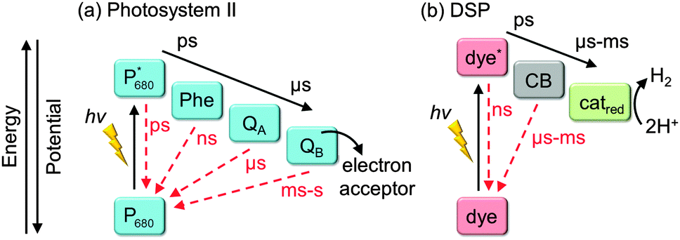 | ||
| Fig. 3 Electron transfer cascades in (a) photosystem II and (b) DSP with separation of light absorption, electron transfer and catalysis. Forward electron transfer and recombination rates are indicated in black and red arrows, respectively. P680: primary electron donor in the reaction centre of PSII photobleaching at λ = 680 nm; Phe: pheophytin (primary electron acceptor); QA: plastoquinone A; QB: plastoquinone B (terminal electron acceptor); CB: conduction band of the semiconductor. | ||
2.2 Component selection and design principles
The overall performance of multi-component systems such as DSP is determined both by the properties of each of the individual components (dye, semiconductor, catalyst, and sacrificial electron donor), and by the strength of the interactions between the components (anchoring groups) under the experimental conditions (pH, concentration, etc.). Therefore, several factors must be considered when selecting components for DSP.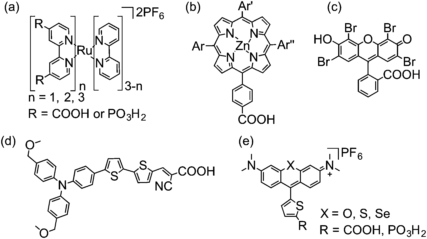 | ||
| Fig. 4 Chemical structures of dyes employed in DSP (shown in fully protonated form): (a) ruthenium bipyridine derivatives,16 (b) porphyrins (Ar = aryl groups),9 (c) Eosin-Y,17 (d) donor–π–acceptor type18 and (e) chalcogenorhodamine dyes.19 | ||
Metal-based dyes can absorb light via a number of transitions that can either be metal-centred or involve metal-to-ligand or ligand-to-metal charge transfers (MLCT and LMCT, respectively).20 For organic dyes, absorption is often due to π–π* transitions. In general, organic dyes consist of less expensive, more abundant elements and have higher molar extinction coefficients than metal-based dyes. However, they are usually more prone to surface aggregation under DSP conditions, affecting their electron transfer properties.19 In addition, metal complexes are generally more photostable, due to the redox flexibility of their metal centre.20
The structure of the dye can play a critical role in the efficiency of electron transfer in dye-sensitised systems. Positioning the lowest unoccupied molecular orbital (LUMO) close to the semiconductor surface allows for good overlap with the orbitals from the semiconductor, enhancing the rate of electron injection.21 Similarly, positioning the highest occupied molecular orbital (HOMO) of the resulting dye cation away from the surface can greatly reduce the rate of recombination following electron injection, enhancing the lifetime of the charge-separated state.21 This tailored synthetic design is exemplified in bipyridine-based Ru dyes and the donor–π–acceptor structure of some organic dyes, in which photoexcited electrons are driven towards the semiconductor surface.22
Although narrow band gap semiconductors that can absorb visible light, such as Cu2O and metal chalcogenides, have been used as light-absorbers for photocatalysis (without an additional dye),24 these materials often suffer from photo-corrosion in water and their properties are often difficult to tune (Fig. 5, right). The most (photo)chemically stable semiconductors are wide band gap metal oxides that only absorb UV light (Fig. 5, left); whereas their absorption of such a small portion of the solar spectrum is limiting in the absence of a dye, in DSP, light absorption primarily occurs at the dye and therefore the valence band (VB) position is irrelevant. The use of a dye can not only avoid side reactions caused by highly reactive VB holes following direct band gap excitation, but also enables the use of semiconductors with greater stability.
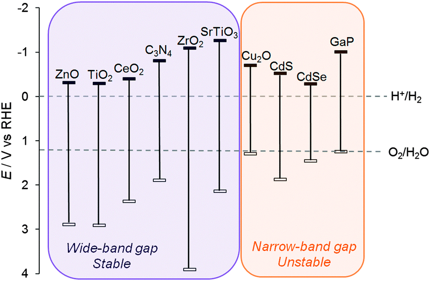 | ||
| Fig. 5 Conduction band and valence band positions of a selection of semiconductors (in V vs. RHE).25 The electrochemical standard potentials for water oxidation and proton reduction are shown for comparison. | ||
TiO2 is by far the most studied semiconductor for both DSC and DSP, and Degussa (Evonik) Aeroxide P25 TiO2 is still one of the most active photocatalysts. P25 typically consists of micrometer sized agglomerates of nanostructured particles (∼21 nm) with an 8![[thin space (1/6-em)]](https://www.rsc.org/images/entities/char_2009.gif) :2 ratio of anatase:rutile crystal phases. The exact reason for the high performance of P25 over anatase or rutile alone is still under debate, but a heterojunction between the two phases might increase charge separation.26 Although electron transfer can occur across a single particle, it has been proposed that nanoparticle agglomeration is beneficial to photocatalytic activity.27 Particles within agglomerates form a conductive network to transport charges, increasing the spatial separation between the charge generation and catalytic sites, and reducing charge recombination.
:2 ratio of anatase:rutile crystal phases. The exact reason for the high performance of P25 over anatase or rutile alone is still under debate, but a heterojunction between the two phases might increase charge separation.26 Although electron transfer can occur across a single particle, it has been proposed that nanoparticle agglomeration is beneficial to photocatalytic activity.27 Particles within agglomerates form a conductive network to transport charges, increasing the spatial separation between the charge generation and catalytic sites, and reducing charge recombination.
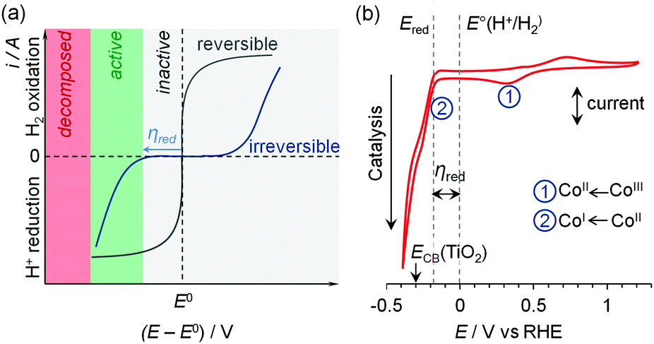 | ||
| Fig. 6 (a) Idealised cyclic voltammograms of reversible and irreversible catalysts in the presence of substrate and product, demonstrating the lack and requirement of a significant overpotential (η) in reversible and irreversible electrocatalysis, respectively. (b) Cyclic voltammogram of a molecular Co catalyst (1, see Fig. 7) demonstrating the key redox processes in pH 7 electrolyte solution.30 The onset of the catalytic proton reduction current is observed following reduction of CoII to CoI. | ||
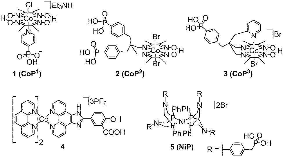 | ||
| Fig. 7 Chemical structures of molecular cobalt and nickel catalysts employed in DSP for H2 evolution (shown as isolated).8,17,30–32 | ||
Platinum and hydrogenases are both thermodynamically reversible electrocatalysts able to catalyse proton reduction and H2 oxidation at a minimal η. However, hydrogenases are fragile, laborious to isolate and purify, and Pt is expensive and of low abundance, limiting practical scale-up of devices to commercial scale. In comparison, the development of molecular catalysts based on 3d transition metals has received much attention as potentially inexpensive and atom-efficient (all metal centres are involved in catalysis) alternatives. Most importantly, they are model materials to study structure–activity relationships, since their active centre is well-defined (‘single-site catalysis’) and tuneable.34
Only a limited number of molecular H2 evolution catalysts suitable for DSP are currently available which display good stability and activity in aqueous solution upon immobilisation on a semiconductor. The synthesis of complexes with suitable anchoring groups is often challenging and the introduction of the anchoring functionality can alter the electronic and steric properties of the catalyst significantly. Surface immobilisation also reduces the probability of interaction between two catalyst molecules and hence catalysts capable of operating via a mononuclear proton reduction mechanism are most likely preferred. The most notable examples of molecular catalysts for DSP are cobalt complexes of the cobaloxime family (1–3, Fig. 7),30–32 a cobalt phenanthroline catalyst (4),17 and a nickel bis(diphosphine) complex (5, Fig. 7).8† The performance of these catalysts in DSP systems will be discussed in further detail below.
Much less is known about the catalyst–semiconductor interface and charge transfer compared to the dye–semiconductor interface. It has been demonstrated recently that the distance between the catalytic centre and the particle surface affects ET and recombination rates in DSP,35 but more detailed studies are required to fully characterise and optimise these processes. In particular, for cobaloximes (e.g.1), electron-donating axial groups are known to enhance activity,36 but common anchoring groups (see below) are typically electronegative and may currently adversely affect the overall DSP activity.
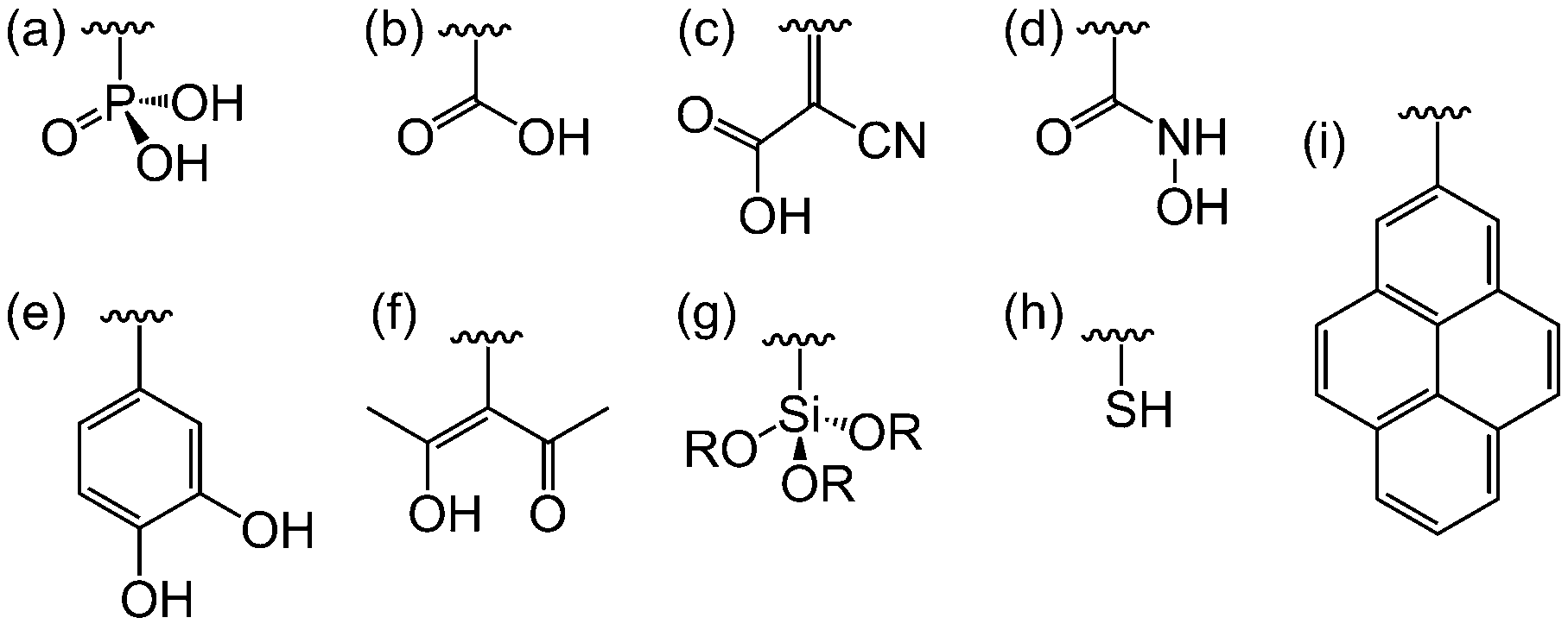 | ||
| Fig. 8 Binding moieties for linkage of dyes and catalysts to semiconductor surfaces: (a) phosphonic acid, (b) carboxylic acid, (c) cyanoacrylic acid, (d) hydroxamic acid, (e) catechol, (f) acetyl-acetone, (g) silane, (h) thiol and (i) pyrene. | ||
DSP systems to date have primarily focused on metal oxide semiconductors, but other classes of semiconductors can also be employed in which case other linkers may be more suitable. For example, thiol groups are commonly used as surface modifiers for metal chalcogenides (Fig. 8h). Non-metal semiconductors such as graphene and carbon nitride (C3N4) could be modified by pyrene anchors via π–π stacking (Fig. 8i).
SEDs can also have secondary roles and care must be taken to ensure that the H2 generated is not a product of SED oxidation,39 and that reactive radicals generated from the SED decomposition do not interfere with the fuel-making reaction.13 It has also been suggested that non-innocent interactions of the SED with the particle surfaces is a key factor for performance.39 Additionally, the degree of interaction of the SED (and other additives) with the molecular catalyst and DSP system is not well understood.
Although SEDs are useful to establish the activity of the reductive half-reaction without limitations by challenging oxidation chemistry, SED oxidation is an energetically consuming rather than energy storing reaction and is therefore an unsustainable component of photocatalytic schemes. Demonstration of efficient DSP in the presence of a SED is therefore often not an effective predictor of function in full water splitting systems. As such, moving away from SED use and towards non-sacrificial systems is a key for future development in this field.
3. Assembly and evaluation of DSP systems
3.1 Assembly of components
DSP systems can be self-assembled in situ or ex situ, depending on the solubility of each component and the degree of competition between the molecular components for binding to the semiconductor nanoparticle surface. If all molecular components are water-soluble and bind quantitatively to the semiconductor, the DSP system can be assembled in situ in the photoreactor by addition of the molecular catalyst and dye to a suspension of the semiconductor nanoparticles (Fig. 9).8,30 A monolayer or sub-monolayer concentrations of the molecular catalyst and dye should be employed, to avoid displacement of the weaker binding component and to maintain a predictable dye to catalyst ratio on the nanoparticle surface. Water-insoluble components can be pre-immobilised in an organic solvent (ex situ), followed by centrifugation and dispersion of the modified semiconductor in the aqueous solution.17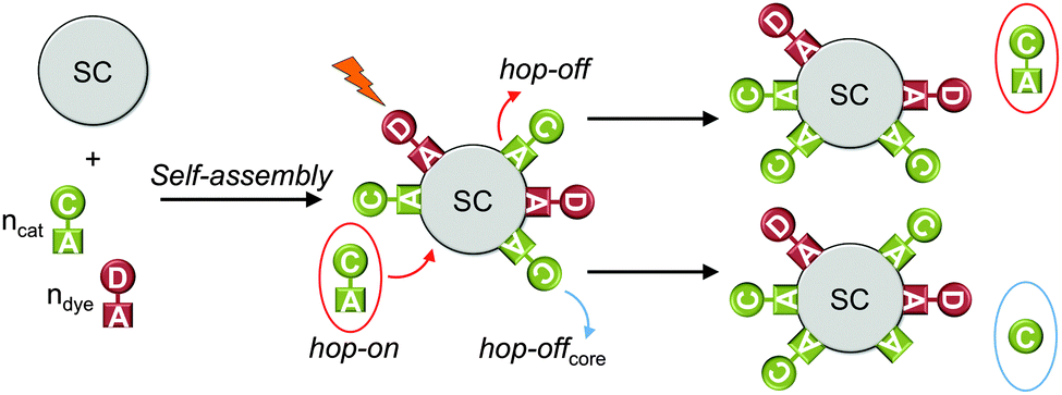 | ||
| Fig. 9 Self-assembly of DSP system and hop-on/hop-off mechanism (shown for catalyst only); hop-on: unbound catalyst molecules occupy free surface sites through self-assembly; hop-off: desorption of catalyst from the particle surface; hop-offcore: loss of catalyst core from the particle surface (anchoring group stays on surface). SC = semiconductor; C = catalyst; D = dye; A = anchoring group.30 | ||
Information about the loading capacity of a semiconductor and anchoring strength of the molecular species to the semiconductor surface can be obtained by electronic absorption (UV-vis), atomic absorption (AAS) and atomic emission (AES) spectroscopies as well as inductively-coupled plasma mass spectrometry (ICP-MS). The amount of adsorbed molecules can be quantified either by comparison of dye and catalyst solutions before and after exposure to the semiconductor (i.e. absorption in UV-vis or concentration in AAS/AES/ICP-MS) or by deliberate desorption of immobilised molecules from the particle surface.
If the molecules are not quantitatively anchored on the surface during the in situ self-assembly, unbound molecules can be in dynamic equilibrium with bound species, where a catalyst or dye molecule can adsorb and desorb from the semiconductor surface (hop-on/hop-off mechanism, Fig. 9).32 In this manner, not all catalyst and dye molecules may be in contact with the semiconductor at a given time, but can contribute to photocatalysis in the course of the bulk experiment. This can be verified by removing the unbound molecules from the particle suspension via centrifugation.8,32 The modified particles are studied for H2 evolution after re-suspension in fresh media and a reduced activity is expected with reduced loading of the catalyst.
The potential-dependent binding ability of the catalyst can be investigated electrochemically when immobilising it on an electrode surface (Fig. 10a and b).31,32 Cyclic voltammetry and chrono-amperometry allows to resolve the stability in different redox states and immobilisation on a transparent substrate provides a means to study the catalyst spectroelectrochemically. The latter allows investigation of the molecular integrity and nature of the catalyst in distinct oxidation states through the oxidation-state-dependent absorption profile (Fig. 10c).
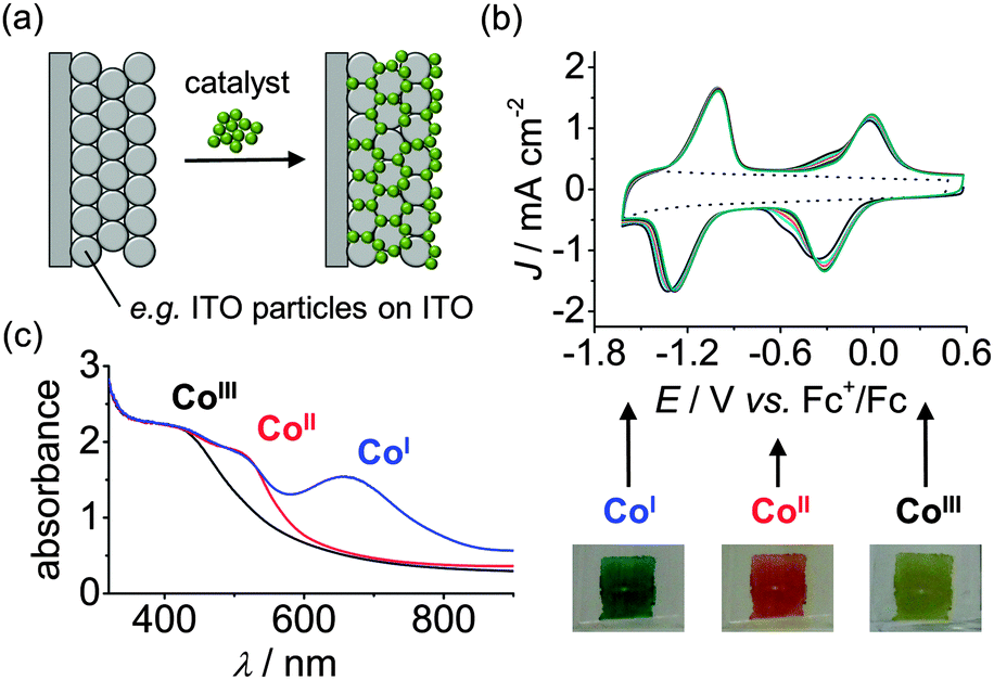 | ||
| Fig. 10 (a) Schematic representation for integration of a molecular catalyst with a mesoporous indium tin oxide (ITO) electrode. (b) Electrochemistry allows for testing anchoring stability: Consecutive cyclic voltammograms of 2 on mesoporous ITO electrodes (in DMF/TBABF4 electrolyte solution). The dotted trace represents the electrode background in the absence of 2. (c) Spectroelectrochemistry of 2 on mesoporous ITO allows for evaluation of the electronic absorption spectra of redox states relevant for catalysis. The photographic pictures depict the colour change of the electrode at different redox potentials.31,32 | ||
3.2 Experimental setup
The primary means of characterising the overall bulk activity of a photocatalytic system is to irradiate a solution or suspension of the photocatalyst and quantify the photo-generated products. Although inexpensive white light sources or light emitting diodes can be used for preliminary experiments, a solar light simulator with an air mass 1.5 (AM 1.5G) filter (the value of 1.5G represents the overall yearly average solar spectrum on the Earth surface, with an incident angle of sunlight of 48.2°) and 1 Sun intensity (100 mW cm−2) should ultimately be employed as a reproducible global standard. Additional filters such as a water filter to exclude IR irradiation help to prevent the reactor from overheating, and other filters may be used to avoid direct excitation of the semiconductor or to study visible light activity only (λ > 400 nm). Monochromatic light irradiation (for example using a bandpass filter or monochromator) is needed for quantum efficiency measurements and to record action spectra.DSP systems should be kept in the dark during assembly and be deaerated prior to testing, as light and O2 can degrade the components or interfere with processes in DSP. The photoreactor with the DSP suspension should be placed into a temperature-controlled water bath to maintain a defined temperature (experiments are typically conducted around ambient temperature) and stirred to ensure mixing of all components throughout the experiment. Photoreactor sizes and designs can vary from small vials to large round bottom flasks with illumination from the front, bottom or with samples arranged around the light source.
Gas chromatography (GC) is commonly used to quantify the amount of H2 in the headspace of the photoreactor. Other quantification methods include mass spectrometry, volumetric detection or pressure monitoring combined with analysis of the gas mixture by GC or Clark-type electrodes for H2 detection. Regular sampling or on-line measurements provide information about the reaction kinetics.
3.3 Key performance parameters and optimisation
The overall amount of H2 produced and long-term activity as well as the TON (eqn (1)), TOF (eqn (2)) and (external) quantum efficiency (EQE, eqn (3)) are important key performance parameters that need to be assessed in DSP: | (1) |
 | (2) |
 | (3) |
The main parameters that can be varied in order to optimise the key performance parameters of a DSP system are temperature, pH, nature and concentration of catalyst, dye, semiconductor or SED, as well as the catalyst/dye, catalyst/semiconductor or dye/semiconductor ratios.
3.4 Characterisation
To confirm the importance of anchoring of the molecular catalyst and dye to the semiconductor for performance, DSP experiments with anchor-free derivatives or in the presence of a reagent that competes for binding sites on the semiconductor (e.g. excess phosphate anions to displace phosphonated molecules) can be performed.13 The importance of electron transfer through the semiconductor particle can be qualitatively evaluated by using a semiconductor with a CB more negative than the excited state oxidation potential of the dye (ECB < ED+/D*).8,41 It should be noted in this context that the close proximity of catalyst and dye on the semiconductor surface could also have a beneficial effect on catalysis such as avoided diffusion-limited kinetics.8 Photocatalytic H2 generation through photoexcitation of the band gap in the absence of dye can be used to confirm direct ET from the semiconductor CB to the catalyst.30,41
UV-vis and IR spectroscopic analyses before, during and after photocatalysis can be used to monitor any change of the molecular catalyst. Energy-dispersive X-ray spectroscopy (EDX), transmission and scanning electron microscopy (TEM, SEM) provide some information about elemental composition of the modified semiconductor surface and allows for the detection of metal nanoparticles on the semiconductor surface, respectively.42 The oxidation states of elements on the semiconductor surface can be best determined by X-ray photoelectron spectroscopy (XPS).31 Other X-ray absorption techniques such as EXAFS (extended X-ray absorption fine structure) and XANES (X-ray absorption near edge structure) provide further insights into the local environment of a single element, e.g. to determine the nature and number of neighbouring atoms.
Control experiments with metal salts instead of the molecular catalyst help to rule out the potential formation of active species such as metal–SED complexes or metal-containing deposits via the reduction of metal ions.32 In addition to anchoring stability, (spectro)electrochemical studies of catalyst–semiconductor hybrid electrodes also provide information about the molecular integrity under reducing conditions (see Fig. 10).31 Finally, if the activity of a degraded DSP system can be reactivated by supplying fresh catalyst or ligand, the active species is likely to be molecular.41
4. Electron transfer kinetics
Kinetic analyses provide supplementary and quantitative information about charge separation and competing recombination pathways, which could limit the performance of the DSP system. The two main time-resolved spectroscopic techniques used to characterise the ET kinetics of hybrid systems for artificial photosynthesis are transient absorption spectroscopy (TAS) and time correlated-single photon counting (TC-SPC).4.1 Transient absorption spectroscopy (TAS)
TAS is a technique that provides information about the dynamics of short-lived transient species that absorb in the visible, near-infrared and infrared region. TAS is a pump–probe experiment, in which a sample is excited with a short intense pulse of light (pump) generated by a pulsed laser, and the resulting changes in absorption (characterised as optical density, ΔO.D.) are monitored through the transmission of a second light source (probe) as a function of time (Fig. 11). Instruments to monitor transient species can be assembled in a range of configurations, to provide information over a wide range of wavelengths and timescales (fs–s).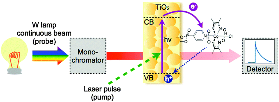 | ||
| Fig. 11 Basic TAS setup. Solid purple lines represent the ETs photoinduced by the laser pulse, whereas the dashed blue arrow represents the recombination reaction and both are being monitored by the probe. | ||
TAS measurements show two main types of contributions to the change in optical transmission: positive signals correspond to the absorption of transient species formed after photoexcitation, while negative signals are generated upon the disappearance of the ground state absorption of species. It is worth noting that if the excited state is luminescent, the probe may trigger stimulated emission, which is recorded as a negative optical density change.
For the study of photocatalytic systems for H2 production, it is important to monitor (1) the spectrum of transient species relevant to the catalysis over a broad range of wavelength at a single time delay (Fig. 12a), and (2) the dynamics of these transient species over a broad range of time delays at a single wavelength (Fig. 12b). The former experiment provides information on the absorption spectra of transient species, allowing the identification of the nature of the species involved in the photocatalytic process; and the latter measurement allows the characterisation of the timescale of formation and disappearance of transient species. Transient absorption decays provide information on the ET kinetics that take place in DSP. The most common parameter used to characterise the charge-carrier lifetime is t50%, defined as the time required for the signal amplitude to decrease half of its initial value (Fig. 12b).
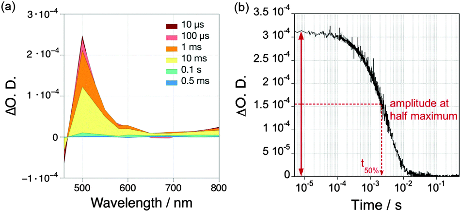 | ||
| Fig. 12 (a) Example of a transient absorption spectrum measured over a broad range of wavelengths at different time delays (10 μs to 0.5 ms); (b) Example of a transient absorption decay recorded at a single wavelength over a broad range of time delays. Examples were taken from ref. 40 and show the TA spectrum and decay of reduced RuP (RuP−, 4 μM), which is formed in ascorbic acid solution (pH 4.5) after excitation at λ = 355 nm.40 | ||
TAS has been used to study the relaxation, recombination and ET reactions of the photogenerated charge carriers in a variety of photochemical systems, including natural photo-synthetic reaction centres, molecular donor–acceptor complexes43 and molecular-based devices8,21,41 for applications in solar cells and solar fuels. In hybrid systems for H2 evolution, the dye, semiconductor and catalyst can all be studied. The ET kinetics can be monitored at different experimental conditions, such as pH, excitation densities, and dye/catalyst loading ratios. This kinetic information, when correlated with bulk catalytic experiments, can highlight catalytic bottlenecks in DSP and provide insightful mechanistic information.
ET transfer from a photoexcited dye to the semiconductor CB can also be studied by monitoring the CB electron signal of the semiconductor instead of the dye species. However, in some cases the dye species might mask the signals from the semiconductor charge carrier.45 To study ET from a semiconductor to a catalyst, direct band gap excitation in the absence of a dye is typically used. For reductive catalysts, a short-lived transient absorption decay of the electron signal in the presence of a hole scavenger is then indicative of a fast and quantitative ET to the catalyst (Fig. 13).35,41,45
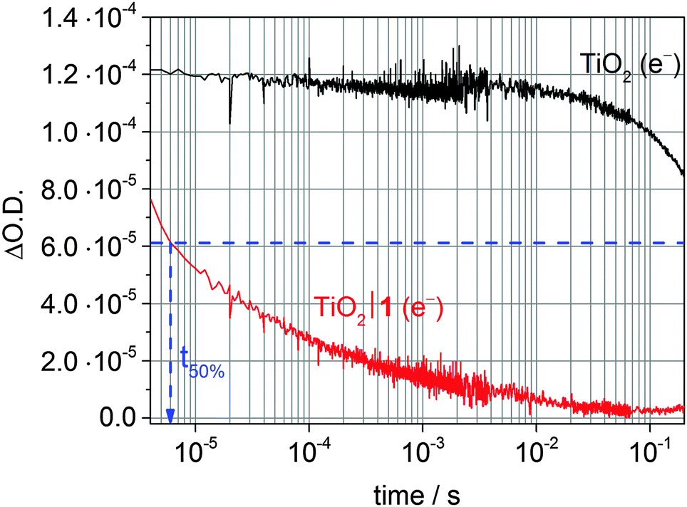 | ||
| Fig. 13 Transient absorption decay of photoexcited TiO2 CB electrons after excitation at λex = 355 nm (λprobe = 900 nm) of a bare TiO2 film (black trace) and when modified with the cobalt catalyst 1 (red trace; see Fig. 7) in the presence of TEOA (0.1 M, pH 7) as sacrificial donor. The blue arrow indicates t50% for the first reduction of the catalyst (CoIII/CoII) based on an initial ΔO.D. of 1.2·10−4.35,41 | ||
4.2 Time correlated-single photon counting (TC-SPC)
TC-SPC is an optical technique that is mainly used to determine the lifetime of molecular excited states, as well as the kinetics of charge/energy transfer in molecular homogeneous or heterogeneous systems, where the excited state of the chromophore is luminescent.8 The operational basis is the detection of single emitted photons as a function of time, typically in the ps–μs timescale. With this technique, the lifetime of the photosensitiser can be measured both in solution or anchored onto the surface of mesoporous nanocrystalline film such as Al2O3, ZrO2 or TiO2.8,41In an inert environment, the luminescence of a molecular dye typically decays within nanoseconds. However, when it is in solution with an easily reducible molecule, or is attached to the surface of a semiconductor with a sufficiently low CB, the luminescence decay of the dye can be quenched due to electron or energy transfer. Therefore, TC-SPC provides information of the timescale at which the electron or energy transfer takes place. In addition, a quantitative measurement of the electron/energy transfer yield can be obtained by integration of the area under the decay, and compared against steady state photoluminescence quenching measurements.41
4.3 Electron transfer kinetics in DSP
Fig. 14 summarises the typical values of electron transfer kinetics of DSP.8,41,45 The overall kinetic requirement in the design of these photocatalytic systems is the matching of the lifetime of the photogenerated charge carriers with the rate of catalytic proton reduction. This challenge can only be achieved by promoting fast and quantitative ETs (solid blue arrows), and by minimising and slowing down the recombination reactions (dashed red arrows). ET across the dye–semiconductor interface has been found to increase charge carrier lifetimes up to the hundreds of microseconds timescale.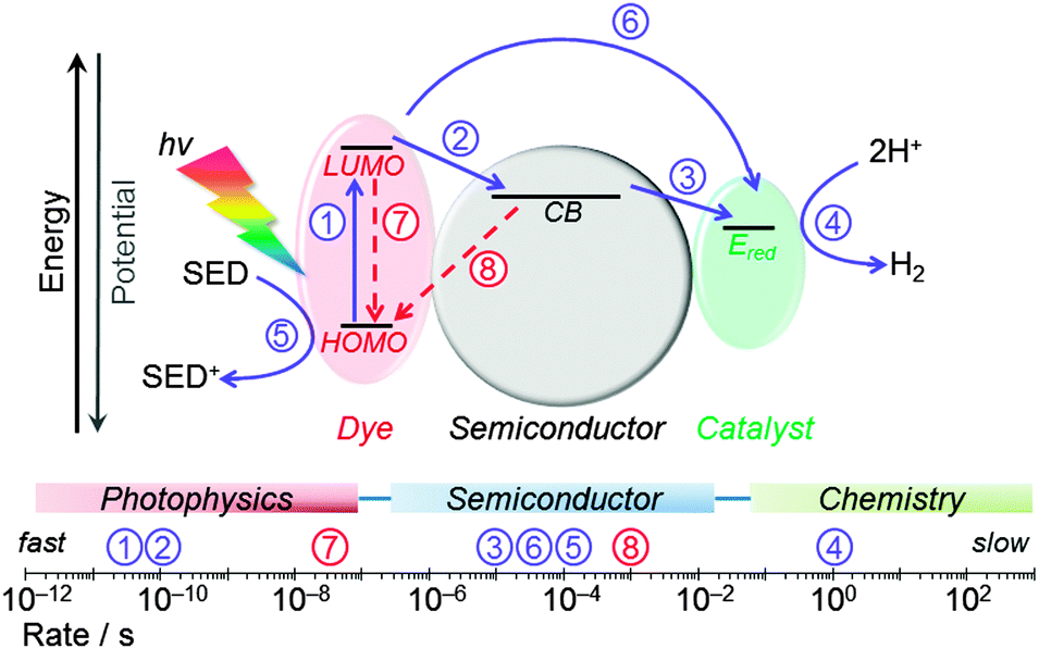 | ||
| Fig. 14 Main kinetic processes considered in the design of DSP systems. Photocatalysis-promoting (forward) electron transfer processes are shown in blue (solid arrows) and recombination pathways in red (dashed arrows). Typical rates determined for RuP|TiO2 modified with molecular catalysts are indicated on the scale bar.8,35,41,451: photoexcitation of dye; 2: electron transfer from photoexcited dye to the semiconductor CB; 3: electron transfer from semiconductor to the catalyst (rate indicates CoIII → CoII reduction process); 4: catalytic reduction of protons to H2; 5: regeneration of the oxidised dye by the sacrificial electron donor; 6: direct electron transfer from photoexcited dye to the catalyst; 7: lifetime of photoexcited state of the dye; 8: charge recombination between semiconductor CB and the oxidised dye. | ||
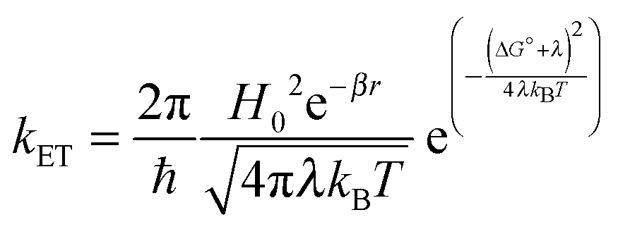
Molecular and device design can be used to control the rate of electron transfer (kET) at the dye–semiconductor and semiconductor–catalyst interfaces. According to Marcus theory, the rate of non-adiabatic ET is given by:
 | (4) |
5. DSP for H2 evolution
5.1 Thermodynamically reversible catalysts
Platinum16 and hydrogenases47 were among the first catalysts applied in DSP for H2 evolution, demonstrating the feasibility of the concept and establishing performance benchmarks.| Entry | Catalyst | Dye|semiconductor | λ /nm | Electron donorb | pH | TONcatc (tirr) | TOFcatd/h−1 (1 h) | Ref. |
|---|---|---|---|---|---|---|---|---|
| a Irradiation wavelength. b EDTA = ethylenediaminetetraacetic acid, TEOA = triethanolamine, TEA = triethylamine, AA = ascorbic acid. c Turnover number (TONcat) is given as mol H2 per mol catalyst. d Turnover frequency (TOFcat) is given as TONcat h−1 based on the first hour of irradiation. e Phosphonate ester derivative of 1: [CoCl(dimethylglyoximato)2(diethylpyridyl-4-phosphonate)]. f Anchor-free derivative of 1: [CoCl(dimethylglyoximato)2(pyridine)]. g 450 W. h 45 mW cm−2. i 100 mW cm−2 (AM 1.5G). j 300 W. k TONcat and TOFcat were calculated assuming an active site consists of two Pt atoms. l No detectable amounts of H2 being produced. | ||||||||
| 1 | Pt | RuP|TiO2 | >420g | EDTA | 3 | ≈135k (3 h) | ≈104k | 16 |
| 2 | [NiFeSe]-hydrogenase | RuP|TiO2 | >420h | TEOA | 7 | (6 ± 0.5) × 105 (4 h) | (1.8 ± 0.1) × 105 | 47 |
| 3 | [NiFeSe]-hydrogenase | C3N4|TiO2 | >300i | EDTA | 6 | >(5.8 ± 0.6) × 105 (72 h) | (2.8 ± 0.3) × 104 | 14 |
| 4 | 1 | RuP|TiO2 | >420i | TEOA | 7 | 108 ± 9 (10 h) | 15.0 ± 0.8 | 13 |
| 5 | 1-estere | RuP|TiO2 | >420i | TEOA | 7 | 13.4 ± 0.7 (4 h) | 4.6 ± 0.2 | 13 |
| 6 | 1 w/o anchorf | RuP|TiO2 | >420i | TEOA | 7 | 11.4 ± 1.3 (4 h) | 3.4 ± 0.2 | 13 |
| 7 | 1 | RuP | >420i | TEOA | 7 | —l (4 h) | —l | 13 |
| 8 | 1 | RuP|ZrO2 | >420i | TEOA | 7 | —l (4 h) | —l | 41 |
| 9 | 2 | RuP|TiO2 | >420i | TEOA | 7 | —l (4 h) | —l | 32 |
| 10 | 3 | RuP|TiO2 | >420i | TEOA | 7 | 22.0 ± 1.5 (4 h) | 9.7 ± 0.4 | 32 |
| 11 | 4 | Eosin-Y|TiO2 | >420j | TEA | 11 | 90 (6 h) | ≈22 | 17 |
| 12 | 4 | Eosin-Y | >420j | TEA | 11 | 8 (3 h) | 4 | 17 |
| 13 | 5 | RuP|TiO2 | >420i | AA | 4.5 | 278 ± 19 (30 h) | 72 ± 5 | 8 |
| 14 | 5 | RuP|ZrO2 | >420i | AA | 4.5 | 524 ± 36 (30 h) | 92 ± 26 | 8 |
000 and TOFcat = 180000 h−1 under visible light irradiation (Table 1). This particular enzyme is known as a ‘titaniaphilic’ hydrogenase and is strongly bound to TiO2 in an electroactive state – presumably with a high concentration of protein surface-exposed carboxylates from aspartate and glutamate residues – facilitating efficient electron transfer from the TiO2-CB to the active centre of the enzyme.47 Recently, a DSP system consisting of [NiFeSe]-hydrogenase and carbon nitride-sensitised TiO2 was reported. A TONcatalyst of >580000 was achieved under full solar spectrum irradiation setting a new benchmark for precious and toxic metal-free DSP for H2 evolution (Table 1).14
5.2 Molecular catalysts
During the last few years, the concept of DSP has been extended from reversible ‘model’ catalysts to synthetic molecular H2 evolution catalysts. The first DSP system with an anchored molecular catalyst was reported in 2011 and consists of TiO2 modified with the phosphonated dye RuP and cobaloxime catalyst 1 (Fig. 7).30 Subsequently, several other cobalt and nickel complexes were employed in DSP (2–5, Fig. 7)8,17,31,32 and the activity and mechanism of these systems will be discussed below. Other examples of molecular catalysts integrated with light-absorbing semiconductors (in the absence of dyes) have been reviewed elsewhere.48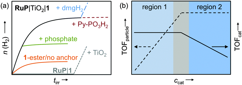 | ||
| Fig. 15 (a) Idealised representation of the activity of 1 on RuP-sensitised TiO2 (black trace) and a range of important control experiments (see text); (b) ‘per particle’ (TOFparticle) and ‘per catalyst’ activity (TOFcat) as a function of catalyst concentration; region 1: catalyst-dependent zone; region 2: light-dependent zone.13,30,41 | ||
The homogeneous multicomponent system RuP|1 was found to be inactive (Table 1), even in the presence of the redox mediator methyl viologen but could be activated by the addition of TiO2 (Fig. 15a, grey trace).13 Activity of the DSP system decreased after several hours of irradiation and could be fully restored by providing new dimethyl glyoxime (dmgH2) ligand (Fig. 15a, blue trace). In this work, degradation of the core ligand was found to be the major deactivation pathway limiting the long-term performance of this DSP system to a few hours. In addition, it also provides further evidence that a molecular species instead of a cobalt-containing deposit was the active H2 evolution catalyst.13,41 Photocatalytic H2 evolution ceased upon addition of phosphate ions (Fig. 15a, green trace) and was significantly lower when the ester or anchor-free derivatives of 1 were used as catalysts (Table 1 and Fig. 15a, orange trace), demonstrating that linkage of the complex to the TiO2 particle and electronic communication via the phosphonic acid moiety was vital for good DSP performance.13,41 When using ZrO2 as semiconductor no H2 was observed, ruling out direct electron transfer from the excited dye to the catalyst on the particle (note that electron injection from RuP* into the ZrO2-CB is not possible due to a too negative CB-edge).41
When optimising for the maximum H2 evolution rate (TOF) of RuP|TiO2|1, two distinct regions were identified (Fig. 15b).13 At low catalyst concentrations, the ‘per particle’ TOF (TOFparticle) increased with the concentration of 1, whereas an approximately constant TOFcat was observed. The overall DSP performance was limited by H2 evolution catalysis rather than light absorption (region 1, catalysis-dependent zone). At a higher concentration of 1, light absorption by the RuP-sensitised TiO2 became the limiting factor (region 2: light-dependent zone) resulting in a constant TOFparticle and decrease of TOFcat. In agreement, H2 evolution activity in region 1 did not change when the light intensity was reduced by using a neutral density filter, whereas a decrease in activity was observed in region 2.
Kinetic investigations of RuP|TiO2|1 under DSP conditions revealed a quantitative and ultrafast electron injection from RuP* to the TiO2-CB (Fig. 16a).41 Charge recombination occurred on the ms timescale, which is significantly slower than in analogous homogeneous systems (ms vs. ps to ns timescale).43 In the presence of a SED, the lifetime of TiO2-CB electrons was further extended to about 0.5 to 1 s (Fig. 13). These long-lived electrons are capable of reducing 1 on the timescale of a few milliseconds (CoIII → CoII, Fig. 16a).41
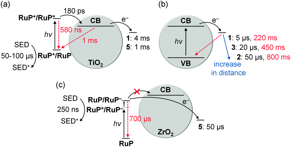 | ||
| Fig. 16 Electron transfer (black arrows) and recombination (red arrows) rates in DSP systems: (a) RuP-sensitised TiO2 in combination with catalyst 1 or 5; (b) distance dependent kinetics determined for catalysts 1–3 on photoexcited TiO2; (c) RuP-sensitised ZrO2 with 5 as catalyst. Electron transfer and recombination rates are given as t50% and were determined for the first reduction of the catalysts only (1–3: CoIII/CoII; 5: NiII/NiI).8,35,41,45 It should be noted that electron transfer rates from the TiO2-CB to the catalyst depend on the electron density in the TiO2-CB, resulting in faster rates in (b) when TiO2 is directly excited across the band gap compared to (a) where electrons are supplied by the excited dye.45 | ||
Despite the notable faradaic efficiency of 1 (>60%) at low overpotential (−0.7 V vs. NHE at pH 7, η = 290 mV),36 the overall EQE of RuP|TiO2|1 is comparably low (1 ± 0.2%).41 This was mainly attributed to slow kinetics for the second reduction (CoII → CoI) of 1, being several orders of magnitude slower than the first reduction (CoIII → CoII).45
It is well known that the axial pyridine ligand in cobaloximes becomes labile after initial reduction and dissociates from the Co(dmgH)2 core.43 Similarly, this dissociation can occur in the particle hybrid (Fig. 9, hop-offcore). Even though the core can readily re-coordinate to the anchored ligand in the particle suspension, a more permanent attachment would in general be preferable.
The molecular cobalt catalyst 2 (Fig. 7) was designed to provide a more stable linkage to the TiO2 surface via the introduction of phosphonic acid anchoring groups to the more robust equatorial diimine–dioxime ligand.31 Spectro-electrochemical studies of 2 immobilised on mesoporous ITO electrodes proved a stronger binding to the metal oxide surface than 1 and high stability of the complex under reducing conditions (Fig. 10).31,32 However, no H2 was observed for 2 on RuP|TiO2 (Table 1) most likely due to a mismatch of the TiO2-CB edge (ECB = −0.7 V vs. NHE at pH 7) and the required potential for proton reduction Ered of 2 in pH 7 TEOA buffer (Ered = −0.72 V vs. NHE).32 Introduction of an axial pyridine ligand into the coordination sphere (3, Fig. 7) lowered the required ηred for H2 evolution by about 70 mV and an optimised TONcat of 22.0 ± 1.5 and TOFcat of 9.7 ± 0.4 h−1 were achieved with RuP|TiO2|3 in pH 7 TEOA buffer (Table 1). The molecular catalyst 3 was identified as the lifetime limiting component in this DSP system, with photocatalysis ceasing after about 4 h of irradiation.32
In a comparative kinetic study of catalyst 1–3 on TiO2, ET and recombination rates between the TiO2-CB and the catalyst and singly reduced species (CoII) and the TiO2-VB, respectively, were determined. Rates correlated with the distance of the catalytic core from the semiconductor surface, resulting in slower rates for forward ET and recombination with increasing distance (Fig. 16b).35 Thus, an optimal catalyst distance from the surface can be envisioned, which allows for sufficiently fast ET and slow enough recombination for optimal catalyst performance.
Finally, a cobalt phenanthroline catalyst (4, Fig. 7) with a salicylic acid anchoring moiety was recently used in DSP. 4 showed higher H2 evolution activity on TiO2 compared to the homogeneous system with Eosin-Y as light-absorber. A TONcat of 90 and TOFcat of about 20 h−1 were achieved in pH 11 aqueous solution with triethylamine as SED (Table 1). In this work, the lifetime of the DSP system was claimed to be limited by dye stability.17 Information about kinetics were not provided for this system.
6. Challenges and future directions
The concept of DSP for light-driven H2 evolution offers several potential advantages over conventional homogeneous approaches: a straightforward self-assembly of the modular system with a rational strategy to optimise performance, and accumulation of multiple, long-lived and high-energy electrons in the conduction band of the semiconductor for the catalyst to collect.Despite this improvement, DSP systems still display rather low efficiencies, low long-term stability, and rely on sacrificial electron donors. To improve performance, in-depth studies on the molecule–semiconductor interface are required to reveal the major pathways accounting for efficiency losses. Only few structure–activity relationships are currently available,32,35 and a better understanding of the electron transfer reactions across the component interfaces will help guide the design of more efficient DSP systems.
The primary source of long-term instability in most reported DSP systems has been the fragility of the molecular photosensitiser and catalyst architecture under photocatalysis conditions. The development of more robust catalysts and strategies to stabilise catalysts on semiconductor surfaces is required in order to produce a step-change in the performance of these systems.
Avoiding sacrificial agents should be a priority in the future development of DSP systems. Ultimately, H2 evolution must be coupled to sustainable oxidation chemistry such as water oxidation in order to become commercially viable. Coupling the proton reduction with the water oxidation half-reaction via a redox mediator (Fig. 17a) or an external circuit in a photoelectrochemcial cell (Fig. 17b) are attractive strategies to remove sacrificial components.5,49,50 Challenges lie in choosing a suitable redox mediator and selecting materials that allow transfer of DSP onto an electrode. An alternative approach is to couple the H2 evolution reaction to other useful one- or two-electron oxidation reactions instead of the 4-electron water oxidation reaction, e.g. oxidation of organic substrates (Fig. 17c). While it is rather straightforward to adjust the thermodynamics of the DSP system to match the required redox potentials of each half-reaction, matching the kinetics of charge separation/recombination and the redox reactions remains highly challenging.
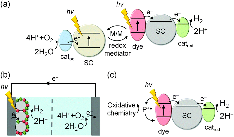 | ||
| Fig. 17 Concepts for non-sacrificial DSP systems: (a) mediated Z-scheme system for full water splitting; (b) immobilisation of a DSP systems on a cathode, which is wired to an anode for water oxidation via an external circuit; (c) dye regeneration in DSP via oxidation of an organic substrate to a higher value chemical. | ||
Ultimately, the DSP approach can be easily applied to other chemical processes, such as the reduction of CO2 to fuels. An early example for the selective photo-conversion of CO2 to CO are phosphonated [Re(2,2′-bipyridine)(CO)3X] (X = leaving group) derivatives, which have recently been used in DSP schemes and exhibited improved long-term stability and activity when anchored to TiO2 in comparison to the corresponding homogeneous systems.3,18 In the future, it can also be anticipated that self-assembly of dye and catalyst on a semiconductor will enable us to synthesise high value chemicals in DSP through organic photocatalysis.
Acknowledgements
This work was supported by the EPSRC (EP/H00338X/2 to E.R.; DTG scholarship to E.P.), the Christian Doppler Research Association (Austrian Federal Ministry of Science, Research and Economy and National Foundation for Research, Technology and Development; E.R. and J.W.), the OMV Group (E.R. and J.W.), the Advanced Institute for Materials Research-Cambridge Joint Research Centre (K.O.), European Commission Marie Curie CIG (303650 to A.R.) and the ERC (291482 to J.D.).Notes and references
- T. R. Cook, D. K. Dogutan, S. Y. Reece, Y. Surendranath, T. S. Teets and D. G. Nocera, Chem. Rev., 2010, 110, 6474–6502 CrossRef CAS PubMed.
- E. V. Kondratenko, G. Mul, J. Baltrusaitis, G. O. Larrazábal and J. Pérez-Ramírez, Energy Environ. Sci., 2013, 6, 3112–3135 CAS.
- C. D. Windle, E. Pastor, A. Reynal, A. C. Whitwood, Y. Vaynzof, J. R. Durrant, R. N. Perutz and E. Reisner, Chem. – Eur. J., 2015, 21, 3746–3754 CrossRef CAS PubMed.
- T. J. Jacobsson, V. Fjällström, M. Edoff and T. Edvinsson, Energy Environ. Sci., 2014, 7, 2056–2070 CAS.
- K. Maeda, ACS Catal., 2013, 3, 1486–1503 CrossRef CAS.
- S. Berardi, S. Drouet, L. Francàs, C. Gimbert-Suriñach, M. Guttentag, C. Richmond, T. Stoll and A. Llobet, Chem. Soc. Rev., 2014, 43, 7501–7519 RSC.
- P. D. Tran, L. H. Wong, J. Barber and J. S. C. Loo, Energy Environ. Sci., 2012, 5, 5902–5918 CAS.
- M. A. Gross, A. Reynal, J. R. Durrant and E. Reisner, J. Am. Chem. Soc., 2014, 136, 356–366 CrossRef CAS PubMed.
- A. Hagfeldt, G. Boschloo, L. Sun, L. Kloo and H. Pettersson, Chem. Rev., 2010, 110, 6595–6663 CrossRef CAS PubMed.
- A. J. Cowan and J. R. Durrant, Chem. Soc. Rev., 2013, 42, 2281–2293 RSC.
- M. Kato, J. Z. Zhang, N. Paul and E. Reisner, Chem. Soc. Rev., 2014, 43, 6485–6497 RSC.
- W. Lubitz, H. Ogata, O. Rüdiger and E. Reijerse, Chem. Rev., 2014, 114, 4081–4148 CrossRef CAS PubMed.
- F. Lakadamyali, M. Kato and E. Reisner, Faraday Discuss., 2012, 155, 191–205 RSC.
- C. A. Caputo, L. Wang, R. Beranek and E. Reisner, Chem. Sci., 2015, 6, 5690–5694 RSC.
- H. Yu, Y. Zhao, C. Zhou, L. Shang, Y. Peng, Y. Cao, L.-Z. Wu, C.-H. Tung and T. Zhang, J. Mater. Chem. A, 2014, 2, 3344–3351 CAS.
- E. Bae and W. Choi, J. Phys. Chem. B, 2006, 110, 14792–14799 CrossRef CAS PubMed.
- M. Yin, S. Ma, C. Wu and Y. Fan, RSC Adv., 2015, 5, 1852–1858 RSC.
- D.-I. Won, J.-S. Lee, J.-M. Ji, W.-J. Jung, H.-J. Son, C. Pac and S. O. Kang, J. Am. Chem. Soc., 2015, 137, 13679–13690 CrossRef CAS PubMed.
- R. P. Sabatini, W. T. Eckenhoff, A. Orchard, K. R. Liwosz, M. R. Detty, D. F. Watson, D. W. McCamant and R. Eisenberg, J. Am. Chem. Soc., 2014, 136, 7740–7750 CrossRef CAS PubMed.
- A. Reynal and E. Palomares, Eur. J. Inorg. Chem., 2011, 4509–4526 CrossRef CAS.
- S. A. Haque, S. Handa, K. Peter, E. Palomares, M. Thelakkat and J. R. Durrant, Angew. Chem., Int. Ed., 2005, 44, 5740–5744 CrossRef CAS PubMed.
- A. Mishra, M. K. R. Fischer and P. Bäuerle, Angew. Chem., Int. Ed., 2009, 48, 2474–2499 CrossRef CAS PubMed.
- K. J. Young, L. A. Martini, R. L. Milot, R. C. Snoeberger III, V. S. Batista, C. A. Schmuttenmaer, R. H. Crabtree and G. W. Brudvig, Coord. Chem. Rev., 2012, 256, 2503–2520 CrossRef CAS PubMed.
- F. E. Osterloh, Chem. Soc. Rev., 2013, 42, 2294–2320 RSC.
- Y. Xu and M. A. A. Schoonen, Am. Mineral., 2000, 85, 543–556 CrossRef CAS.
- J. T. Carneiro, T. J. Savenije, J. A. Moulijn and G. Mul, J. Phys. Chem. C, 2011, 115, 2211–2217 CAS.
- Y. Park, W. Kim, D. Monllor-Satoca, T. Tachikawa, T. Majima and W. Choi, J. Phys. Chem. Lett., 2013, 4, 189–194 CrossRef CAS PubMed.
- V. Artero and J.-M. Saveant, Energy Environ. Sci., 2014, 7, 3808–3814 CAS.
- F. A. Armstrong and J. Hirst, Proc. Natl. Acad. Sci. U. S. A., 2011, 108, 14049–14054 CrossRef CAS PubMed.
- F. Lakadamyali and E. Reisner, Chem. Commun., 2011, 47, 1695–1697 RSC.
- N. M. Muresan, J. Willkomm, D. Mersch, Y. Vaynzof and E. Reisner, Angew. Chem., Int. Ed., 2012, 51, 12749–12753 CrossRef CAS PubMed.
- J. Willkomm, N. M. Muresan and E. Reisner, Chem. Sci., 2015, 6, 2727–2736 RSC.
- S. Cobo, J. Heidkamp, P.-A. Jacques, J. Fize, V. Fourmond, L. Guetaz, B. Jousselme, V. Ivanova, H. Dau, S. Palacin, M. Fontecave and V. Artero, Nat. Mater., 2012, 11, 802–807 CrossRef CAS PubMed.
- J. R. McKone, N. S. Lewis and H. B. Gray, Chem. Mater., 2014, 26, 407–414 CrossRef CAS.
- A. Reynal, J. Willkomm, N. M. Muresan, F. Lakadamyali, M. Planells, E. Reisner and J. R. Durrant, Chem. Commun., 2014, 50, 12768–12771 RSC.
- D. W. Wakerley and E. Reisner, Phys. Chem. Chem. Phys., 2014, 16, 5739–5746 RSC.
- L. Zhang and J. M. Cole, ACS Appl. Mater. Interfaces, 2015, 7, 3427–3455 CAS.
- C. Law, S. C. Pathirana, X. Li, A. Y. Anderson, P. R. F. Barnes, A. Listorti, T. H. Ghaddar and B. C. O'Regan, Adv. Mater., 2010, 22, 4505–4509 CrossRef CAS PubMed.
- M. Ni, M. K. H. Leung, D. Y. C. Leung and K. Sumathy, Renewable Sustainable Energy Rev., 2007, 11, 401–425 CrossRef CAS.
- A. Reynal, E. Pastor, M. A. Gross, S. Selim, E. Reisner and J. R. Durrant, Chem. Sci., 2015, 6, 4855–4859 RSC.
- F. Lakadamyali, A. Reynal, M. Kato, J. R. Durrant and E. Reisner, Chem. – Eur. J., 2012, 18, 15464–15475 CrossRef CAS PubMed.
- V. Artero and M. Fontecave, Chem. Soc. Rev., 2013, 42, 2338–2356 RSC.
- B. S. Veldkamp, W.-S. Han, S. M. Dyar, S. W. Eaton, M. A. Ratner and M. R. Wasielewski, Energy Environ. Sci., 2013, 6, 1917–1928 CAS.
- T. Berger, M. Sterrer, O. Diwald, E. Knözinger, D. Panayotov, T. L. Thompson and J. T. Yates, Jr., J. Phys. Chem. B, 2005, 109, 6061–6068 CrossRef CAS PubMed.
- A. Reynal, F. Lakadamyali, M. A. Gross, E. Reisner and J. R. Durrant, Energy Environ. Sci., 2013, 6, 3291–3300 CAS.
- J. L. Dempsey, J. R. Winkler and H. B. Gray, J. Am. Chem. Soc., 2010, 132, 1060–1065 CrossRef CAS PubMed.
- E. Reisner, D. J. Powell, C. Cavazza, J. C. Fontecilla-Camps and F. A. Armstrong, J. Am. Chem. Soc., 2009, 131, 18457–18466 CrossRef CAS PubMed.
- M. Wang, K. Han, S. Zhang and L. Sun, Coord. Chem. Rev., 2015, 287, 1–14 CrossRef CAS.
- Z. Yu, F. Li and L. Sun, Energy Environ. Sci., 2015, 8, 760–775 CAS.
- P. Meng, M. Wang, Y. Yang, S. Zhang and L. Sun, J. Mater. Chem. A, 2015, 3, 18852–18859 CAS.
Footnote |
| † The molecular catalysts 1 (CoP1, CAS: 27-3015) and 5 (NiP, CAS: 28-1720) are commercially available via Strem Chemicals. The photosensitiser RuP (CAS: 239472-59-4) is available from Dyenamo AB. |
| This journal is © The Royal Society of Chemistry 2016 |