
 Open Access Article
 This Open Access Article is licensed under a Creative Commons Attribution-Non Commercial 3.0 Unported Licence
Should “anion–π interactions” be called “anion–σ interactions”? A revision of the origin of some hole-bonds and their nomenclature
S.
Kozuch

Department of Chemistry, Ben-Gurion University of the Negev, Beer-Sheva 841051, Israel. E-mail: kozuch@bgu.ac.il
First published on 12th October 2016
Abstract
The so-called anion–π interactions are dissected to test if indeed the π system of the aromatic ring is the reason for the bond. In contrast, due to σ–holes the σ system is found to be responsible for a “pseudo-π hole” interaction. Models that form genuine anion–π bonds are discussed.
Anion–π (or, similarly, lone pair–π) interactions can be roughly defined as the bond forming between an anion or a Lewis base and electron deficient aromatic systems.1–10 Considering that the π cloud in any aromatic molecule is inherently formed by negative electrons, this interaction with another negatively charged entity is, at the least, counterintuitive. However, the analysis of the quadrupole moment11 of, for instance, hexafluorobenzene, shows an inversion of the polarity above the ring compared to the quadrupole moment of benzene [Qzz(C6H6) = −8.5 B, Qzz(C6F6) = +9.5 B].7,8 This suggests that the net charge over the ring of aromatic species with strong electron-withdrawing substituents is positive, which would explain why the electrostatic interaction with anions is possible. Being a non-covalent interaction (NCI) between an electron density depleted region (an electronic hole) and an anion (the hole acceptor) standing perpendicularly to the covalent bonds, this has been considered as part of the “π–hole interactions”1,10,12–19 (opposed to σ–hole interactions,20 which are at an angle of ∼180° to the covalent bond). In other words, an anion will tend to make an NCI right over the centre of the C6F6 plane, and being at 90° to each F–C bond, it is considered a π–hole bond. Herein we will dissect this interaction and argue that these NCIs are not formed from the π MOs but from the σ structure. These bonds are linked to σ–holes and not to π–holes, in what should be called a pseudo-π interaction (a term recently coined by Li et al.21).
A proper σ–hole is created when a covalent bond is formed, bringing electronic density from s and pz AOs to the region between the nuclei (leaning to the more electronegative atom). This inward concentration depletes the negative charge from the exterior side of the bond, especially from the more electropositive atom, creating a positive electrostatic hole in line with the bond.20 In this sense, we can check the position and direction of the hole by looking at the electrostatic potential (ESP) of the molecule. This typically matches the electron distribution at the highest σ MO,22 where the sections with higher electron density of the orbital tend to coincide with the more negative parts of the molecule, and where the electrons are depleted the nuclear positive charge becomes predominant, forming electrostatic holes, as can be seen in Fig. 1 (all computations were carried out at the M06-2X23/Def2-TZVPD level,24,25 adequate for NCIs,26,27 using Gaussian09;28 the ESPs are drawn using GaussView29 at an isodensity of 0.01 a.u.). Less considered is the origin of the π–hole, which (at least according to the classification presented here) has the same rationalization but involves the higher π MOs, as can be seen, for instance, over the carbon of formaldehyde in Fig. 1B (note that between the hydrogens in the plane of the molecule also appears a positive potential, indicating a small σ–hole).22 As we shall see, this explanation is at odds with most cases of what are frequently considered π–holes (i.e. NCIs to electrostatic holes at ∼90° of the covalent bond).1,10,12–18
 | ||
Fig. 1 First column: Electrostatic potentials (ESPs) colour coded at the maximum and minimum potentials for each system ([−0.030;0.237] Ha for FI, [−0.064;0.112] for H2C![[double bond, length as m-dash]](https://www.rsc.org/images/entities/char_e001.gif) O, [−0.033;0.188] for F2CO, [−0.029;0.092] for H2CCH2, [−0.010;0.121] for F2CCF2 and [0.004;0.119] for F2CCF2, red corresponding to a relative negative potential and blue to a relative positive potential). Second column: Colour coded ESPs from 0.0 to 0.2 Ha, for comparative purposes. Third column: Relevant occupied MOs. O, [−0.033;0.188] for F2CO, [−0.029;0.092] for H2CCH2, [−0.010;0.121] for F2CCF2 and [0.004;0.119] for F2CCF2, red corresponding to a relative negative potential and blue to a relative positive potential). Second column: Colour coded ESPs from 0.0 to 0.2 Ha, for comparative purposes. Third column: Relevant occupied MOs. | ||
Double bonds with electronegative atoms enhance the π–hole (compare ethene and formaldehyde ESPs, Fig. 1B and D), but single bonds with specific electronegative groups may also enhance the same hole: carbonyl difluoride (Fig. 1C) shows an enhanced π–hole (electronic depletion) due to the antibonding interaction of the p AOs of the fluorides with the CO π MO. In contrast, the small σ–hole that appeared in H2CO is almost inexistent in F2CO, due to the inductive effect of the fluorides. It appears that halides, being σ acceptors but π donors, influence the different holes in opposite directions. Indeed, Fig. 1D shows that ethene does not have a distinguishable π–hole, but 1,1-difluoroethene (Fig. 1E) and even tetrafluoroethene (Fig. 1F), without any dipole moment, produce a subtle π–hole. The comparison of the shapes of CO and CC π orbitals (third column in Fig. 1) reveals this drop of π electron density when having a π acceptor in the double bond and a π donor in the single bonds.
It is noteworthy that F2CCF2 shows a σ–hole between cis fluorides, due to the complementary effect of the opposite side fluorides. There is a vectorial addition of the electron withdrawing power of the same side F atoms, converging between the carbons at the opposite side of the two fluorides in the σ-plane. These observations will let us comprehend the singular ESP of hexafluorobenzene (C6F6), the central molecule in this communication.
The concept of anionic–π interactions essentially started with the counterintuitive observation of an NCI between C6F6 and anionic atoms and molecules. These interactions are usually directed to the centre of the ring (“η6” interaction), although some other configurations were also observed (η1, η2 or η3, pointing to one, two or three carbons7). It seems to be contradictory that the π cloud can allow the quadrupole inversion that occurs when moving from benzene to hexafluorobenzene,7,8 especially considering that fluorides might be σ electron acceptors, but are also π electron donors. In contrast, as seen in the previous paragraph and in Fig. 1C, E and F, fluorides may enhance the π–hole. Hence, are these “anionic–π” interactions based on the aromatic π system or not?
Fig. 2A and B depict the ESP of benzene and hexafluorobenzene at their maximum potential range (to detect relatively positive areas, i.e. electronic holes), and between 0.0 and 0.2 Ha (to compare all hole sizes and potencies on the same foot). In both cases we can see a relatively negative potential directly above the carbon atom hexagon (clearly more negative in the case of benzene). This indicates that, although diminished, the π electrons of C6F6 are still setting a negative environment, which comes at odds with the supposition that an anion can get bound through the π system or that an inverse quadrupole should develop. What appears as the origin of such “anion–π” η6 interactions is the blue dot in the middle of the ring, which reaches its maximum potential in the plane of the molecule. Similar to tetrafluoroethene (Fig. 1F), this build-up of positive charge can actually be traced to a collective σ–hole (“tetrel bond”30) produced by the converging F–C bonds. In other words, what is typically considered an anion–π interaction is actually an anion–σ interaction, or what should be appropriately called a pseudo-π interaction.21
Hexafluorobenzene not only contains a central electrostatic hole, but also shows a hexagonal perimeter of positive charge, as can be seen in blue at the left ESP in Fig. 2B. Similarly to the tetrafluoroethene model (Fig. 1F), there are two factors that form the positive external ring. First, in the plane of the ring and between the fluorides we have the electron depletion caused by the two σ–holes from the σ C–C bonds. Second, the positive surface around the C–F bond is a sum of the real π–holes formed due the π electron donor ability of the fluorides; this is the only topographical part that might, theoretically, form a genuine anion–π interaction. However, after some computational attempts with a chloride as a model anion, no stable geometry was found that would connect the hole acceptor with the π–hole. Therefore, the outer positive ring is an amalgamation of σ and π holes, but being in the outskirt of the aromatic ring they do not contribute to the η6 pseudo-π bond. Fig. 2C shows the case of hexacyanobenzene, whose substituents have a similar inductive effect compared to fluoride, but without the resonance contribution (π donation) the aromatic density and the π–holes are, not surprisingly, contracted. This again shows that the π system inhibits the potential interaction with anions, and therefore it is misleading to call these NCIs anion–π bonds.
 | ||
| Fig. 2 First column: ESPs at their maximum potentials ([−0.011;0.095] Ha for C6H6, [−0.001;0.107] for C6F6, [−0.037;0.169] for C6(CN)6). Second column: ESPs between 0.0 and 0.2 Ha. Black lines indicate the positions of the atoms. | ||
Fig. 3 shows the interaction between a Cl− ion and C6F6, superposed to the cut-out of three ESPs of the aromatic molecule (a C6v optimal geometry of the dimer, with the anion at 3.15 Å above the ring plane). This picture illustrates the electrostatic interaction between the Cl− and the σ–hole. NBO calculations do not show any significant charge transfer contribution for this compound, leaving the electrostatic interaction as the main binding force, and polarization as a minor contributor, as described elsewhere.7,31 Optimizing this dimer is a tricky task due to the extremely flat potential of the anion “surfing” over the accessible surface of the aromatic ring.5,7,32 Different computational methods may produce different optimal geometries, with several functionals and basis sets generating spurious imaginary frequencies for the C6v symmetry. We resorted to the much more accurate (and computationally expensive) DSD-PBE-P86-D3BJ33,34 double hybrid to confirm the stability of the symmetrical system. The resulting bond energy is 62 kJ mol−1 at the M06-2X/Def2TZVPD level, and virtually the same (61 kJ mol−1) with the double hybrid and the same basis set. This is a significantly strong NCI bond, considering that it is based on an electrostatic interaction perpendicular to the σ–holes.
 | ||
| Fig. 3 Interaction between Cl− and F6C6. The surfaces correspond to the cut-out ESPs of hexafluorobenzene at 10−2, 10−3 and 10−4 a.u. isodensity values (red = 0.0 Ha; blue = 0.1 Ha). | ||
What can be considered a genuine anionic–π interaction in a ring system? For that, we should have a real π–hole converging system. As seen in Fig. 1C, carbonyl groups can be considered the prototypical molecular block to obtain this effect. Consequently, cyclohexanehexone [(CO)6] definitely shows a strong hole at the inner side or the six-carbon ring (Fig. 4A) which, being mostly a sum of six π–holes, is much more pronounced than the converging σ–hole of C6F6. This almost planar D3d system can bind Cl− with a much stronger interaction compared to the previous σ–hole based system. The computed dissociation energy of C6O6⋯Cl− is 271 kJ mol−1 (with M06-2X in a C6v geometry for the dimer). This is not unexpected, since the π–holes are almost aligned with the chloride hanging over the midpoint of the ring (contrary to the σ–holes of C6F6, which are perpendicular to the anion). Being aligned, there is also a larger orbital superposition allowing an additional charge-transfer interaction. While an NBO analysis of C6F6⋯Cl− did not show any significant charge transfer between monomers, for C6O6⋯Cl− there are substantial contributions from the p AOs of the anion to the CO π* MOs (ΔE2 = 21 kJ mol−1 for each pz → π*, and 13 kJ mol−1 for each px + py → π*).
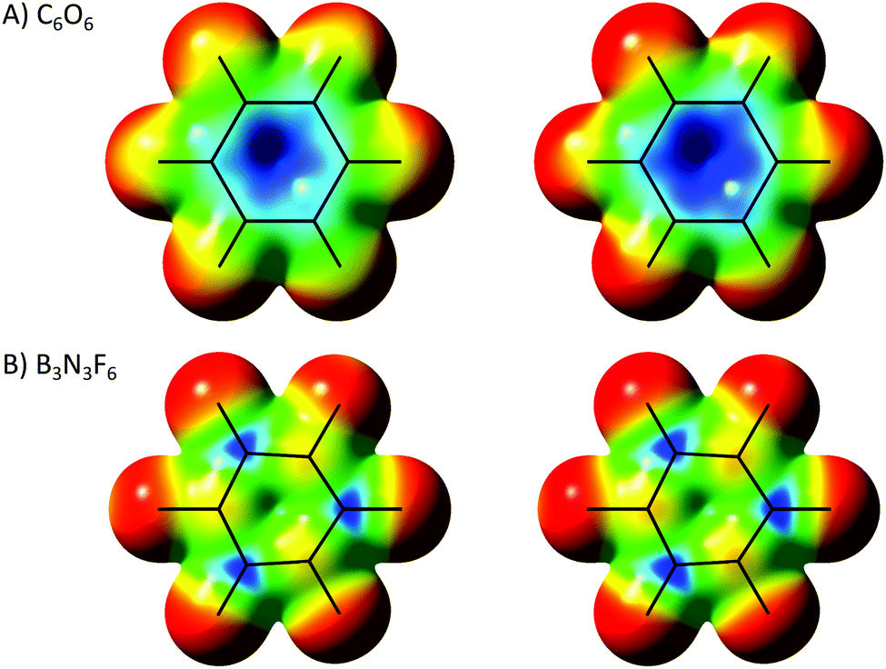 | ||
| Fig. 4 ESPs of cyclohexanehexone and hexafluoroborazine at their maximum potentials ([−0.028;0.220] for C6O6 and [−0.008;0.208] for B3N3F6), and between 0.0 and 0.2 Ha for comparative purposes. | ||
Another type of commonly considered π–hole arises from pz electron deficient atoms, such as boron.35Fig. 4B depicts hexafluoroborazine (B3N3F6) where, as expected, positive areas are found right above the B atoms (boron is a classical Lewis acid after all). In the jargon proposed here this should not be called a π–hole, since it does not actually originate from a π MO, but it can be called a p–hole, as it is rooted on an individual atomic orbital (it can still be considered a pseudo-π hole, as it binds Lewis bases perpendicular to the ring plane). Note that the focal point of a π–hole, formed from the displacement of π electrons, cannot be exactly over the atom but just beyond the double bond. However, p–holes must have their epicentre right over the atom in question.
Chlorides, being hard anions, tend to form short covalent bonds with a single boron instead of an NCI with the whole hexafluoroborazine. However, Br− and I− can generate meta-stable NCIs with C3v symmetries, interacting with the three borons. For comparative purposes, we can still carry out an NBO calculation on the unstable B3N3F6⋯Cl−C3v dimer, which gives ΔE2 values of 19 and 9 kJ mol−1 for pz and px + py to B–N π* MOs (basically a charge transfer from Cl− to the boron pz AOs). Similar to π–holes, the directionality of the p–holes permits a good orbital superposition with the anion, thus allowing the charge transfer. The dissociation energy of the B3N3F6⋯Cl−C3v dimer is 102 kJ mol−1.
To sum up, F6C6 has a genuine σ–hole at the centre of the ring that, due to the molecular geometry, is only accessible from a parallel to the plane direction (a pseudo-π hole). This is the main driving force for the misleadingly called anionic–π bond, which should be called the anionic–pseudo-π bond. Describing this interaction only based on the quadrupole moment is not a complete explanation, as it does not elucidate on the origin of that moment. True anionic–π bonds can be made from systems with converging π–holes, such as C6O6. Electron deficient atoms in ring systems (such as borons in borazines) have holes not originating from the forced electron depletion caused by covalent bonds as in π or σ–holes, but from the natural absence of pz electrons; therefore, if we want to label them according to the same terminology, we can call them p–holes. To distinguish between these different holes (σ, π and p) in rings, it is possible to check the charge transfer and the hole position. Because of the ability to participate in orbital superposition, only π and p–holes can have a charge transfer component. The position of the hole can discriminate between the interactions, with the σ–hole being in the plane of the molecule, the π–hole over the plane but slightly displaced from the electropositive atom, and the p–hole standing precisely over the atom.
Although this debate does not change in any form the reality of the interaction energies of pseudo-π bonds, it can help to comprehend the nature of those chemical bonds. An accurate nomenclature is not just a pedantic obsession if it gives insights beyond numbers.
This research was supported by the Israel Science Foundation (grant 631/15), the Lise Meitner-Minerva Center for Computational Quantum Chemistry, and a start-up grant from the Ben-Gurion University of the Negev.
Notes and references
- H. Wang, W. Wang and W. J. Jin, Chem. Rev., 2016, 116, 5072–5104 CrossRef CAS PubMed
.
- M. Mascal, A. Armstrong and M. D. Bartberger, J. Am. Chem. Soc., 2002, 124, 6274–6276 CrossRef CAS PubMed
- S. E. Wheeler, Acc. Chem. Res., 2013, 46, 1029–1038 CrossRef CAS PubMed
- J. C. Amicangelo, D. G. Irwin, C. J. Lee, N. C. Romano and N. L. Saxton, J. Phys. Chem. A, 2013, 117, 1336–1350 CrossRef CAS PubMed
- A. Frontera, P. Gamez, M. Mascal, T. J. Mooibroek and J. Reedijk, Angew. Chem., Int. Ed., 2011, 50, 9564–9583 CrossRef CAS PubMed
- C. Foroutan-Nejad, Z. Badri and R. Marek, Phys. Chem. Chem. Phys., 2015, 17, 30670–30679 RSC
- M. Giese, M. Albrecht and K. Rissanen, Chem. Rev., 2015, 115, 8867–8895 CAS
- C. Garau, A. Frontera, D. Quiñonero, P. Ballester, A. Costa and P. M. Deyà, ChemPhysChem, 2003, 4, 1344–1348 CrossRef CAS PubMed
- D.-X. Wang and M.-X. Wang, J. Am. Chem. Soc., 2013, 135, 892–897 CrossRef CAS PubMed
- D. Quiñonero, C. Garau, C. Rotger, A. Frontera, P. Ballester, A. Costa and P. M. Deyà, Angew. Chem., Int. Ed., 2002, 41, 3389–3392 CrossRef
- J. H. Williams, Acc. Chem. Res., 1993, 26, 593–598 CrossRef CAS
- X. Pang, H. Wang, X. R. Zhao and W. J. Jin, CrystEngComm, 2013, 15, 2722 RSC
- A. Bauzá, R. Ramis and A. Frontera, J. Phys. Chem. A, 2014, 118, 2827–2834 CrossRef PubMed
- X. Q. Yan, X. R. Zhao, H. Wang and W. J. Jin, J. Phys. Chem. B, 2014, 118, 1080–1087 CrossRef CAS PubMed
- T. Lang, X. Li, L. Meng, S. Zheng and Y. Zeng, Struct. Chem., 2015, 26, 213–221 CrossRef CAS
- L. Gao, Y. Zeng, X. Zhang and L. Meng, J. Comput. Chem., 2016, 37, 1321–1327 CrossRef CAS PubMed
- Y. Zhang, N. Ma and W. Wang, Chem. Phys. Lett., 2012, 532, 27–30 CrossRef CAS
- E. L. Zins and M. E. Alikhani, Mol. Phys., 2016, 114, 1317–1325 CrossRef CAS
- J. S. Murray, P. Lane, T. Clark, K. E. Riley and P. Politzer, J. Mol. Model., 2012, 18, 541–548 CrossRef CAS PubMed
- T. Clark, Wiley Interdiscip. Rev.: Comput. Mol. Sci., 2013, 3, 13–20 CrossRef CAS
- W. Li, Y. Zeng, X. Li, Z. Sun and L. Meng, Phys. Chem. Chem. Phys., 2016, 18, 24672–24680 RSC
- O. Kirshenboim and S. Kozuch, J. Phys. Chem. A, 2016, accepted Search PubMed.
- Y. Zhao and D. G. Truhlar, Theor. Chem. Acc., 2008, 120, 215–241 CrossRef CAS
- K. L. Schuchardt, B. T. Didier, T. Elsethagen, L. Sun, V. Gurumoorthi, J. Chase, J. Li and T. L. Windus, J. Chem. Inf. Model., 2007, 47, 1045–1052 CrossRef CAS PubMed
- D. Rappoport and F. Furche, J. Chem. Phys., 2010, 133, 134105 CrossRef PubMed
- S. Kozuch and J. M. L. Martin, J. Chem. Theory Comput., 2013, 9, 1918–1931 CrossRef CAS PubMed
- L. P. Wolters, P. Schyman, M. J. Pavan, W. L. Jorgensen, F. M. Bickelhaupt and S. Kozuch, Wiley Interdiscip. Rev.: Comput. Mol. Sci., 2014, 4, 523–540 CrossRef CAS
-
M. J. Frisch, et al., Gaussian 09, Rev. D01, Gaussian, Inc., Wallingford CT, 2009 Search PubMed
-
R. Dennington, T. Keith and J. Millam, GaussView Version 5 Search PubMed
- A. Bauzá, T. J. Mooibroek and A. Frontera, Angew. Chem., Int. Ed., 2013, 52, 12317–12321 CrossRef PubMed
- Z. A. Tehrani, Z. Jamshidi and H. Farhangian, J. Mol. Model., 2013, 19, 4763–4772 CrossRef PubMed
- C. Estarellas, A. Bauzá, A. Frontera, D. Quiñonero and P. M. Deyà, Phys. Chem. Chem. Phys., 2011, 13, 5696–5702 RSC
- S. Kozuch and J. M. L. Martin, Phys. Chem. Chem. Phys., 2011, 13, 20104–20107 RSC
- S. Kozuch and J. M. L. Martin, J. Comput. Chem., 2013, 34, 2327–2344 CAS
- H. Zhuo, Q. Li, W. Li and J. Cheng, Phys. Chem. Chem. Phys., 2013, 16, 159–165 RSC
| This journal is © the Owner Societies 2016 |