
 Open Access Article
 This Open Access Article is licensed under a Creative Commons Attribution-Non Commercial 3.0 Unported Licence
Solvent effects on ion–receptor interactions in the presence of an external electric field†
Martin
Novák
a,
Cina
Foroutan-Nejad
*a and
Radek
Marek
 ab
ab
aCEITEC – Central European Institute of Technology, Masaryk University, Kamenice 5/A4, CZ-625 00, Brno, Czech Republic. E-mail: cina.foroutannejad@ceitec.muni.cz
bDepartment of Chemistry, Faculty of Science, Masaryk University, Kamenice 5/A4, CZ-625 00 Brno, Czech Republic
First published on 19th October 2016
Abstract
In this work we investigated the influence of an external electric field on the arrangement of the solvent shells around ions interacting with a carbon-based receptor. Our survey reveals that the mechanism of interaction between a monoatomic ion and a π-type ion receptor varies by the variation in the solvent polarity, the nature of the ion, and the strength of the external field. The characteristics of the ion–surface interaction in nonpolar solvents are similar to those observed in a vacuum. However, in water, we identified two mechanisms. Soft and polarizable ions preferentially interact with the π-receptor. In contrast, two bonded states were found for hard ions. A fully solvated ion, weakly interacting with the receptor at weak field, and a strong π-complex at the strong-field regime were identified. An abrupt variation in the potential energy surface (PES) associated with the rearrangement of the solvation shell on the surface of the receptor induced by an external field was observed both in implicit and explicit solvent environments. The electric field at which the solvation shell breaks is proportional to the hardness of the ion as has been suggested recently based on experimental observations.
1. Introduction
An external electric field (EEF) can modulate the nature and strength of intermolecular interactions,1–4 affect the products of known chemical processes,5–9 energies of the electronic states10,11 and consequently response properties of molecules.12–15 The EEF has been employed for molecular sensing16,17 and recently for catalysis.18–20 Carbon nanostructures, in particular graphene,21 because of their polarizable extended π-systems are a fascinating class of materials whose properties can be influenced considerably by means of an EEF.22 Graphene has been used for manufacturing state-of-the-art electronic devices such as high capacity batteries,23–26 super-capacitors,27–34 and field-effect transistors.35–38 These technological advances necessitate to gain a fundamental understanding of the mechanism of electric-field-induced chemical processes to improve future experiments.39The dynamic processes on the ion/solvent–graphene interface in the presence or absence of the electric fields have been studied by many researchers to gain a better understanding of the physiochemical processes in batteries and super-capacitors.40–47 Several groups have studied the interactions of ions,48,49 metal atoms,50–63 metallic clusters,64 or molecules65–67 with carbon nanostructures by quantum mechanical approaches mainly in the absence and seldom in the presence of the external electric fields. However, until very recently ion–surface interactions have not been studied at a state-of-the-art quantum mechanical level in the presence of an EEF.68–70
Recent studies have suggested that a uniform EEF can strengthen ion/molecule–graphene interactions by increasing the electron sharing between two species.1,69,70 The magnitude of the electron sharing is influenced by the extent of the state-mixing between the singlet excited-states of the system and its electronic ground-state.71 We term this phenomenon electric bond strengthening, in analogy with the electric bond softening.72,73 A very strong electric field ultimately initiates the electron-transfer process between the carbon nanostructures74 and the ions, which results in dissociation of the ion–receptor complex. Our recent studies in the gas-phase suggest that electron transfer may occur via formation of a covalent intermediate between the donor and the acceptor.71
Because a great number of chemical phenomena take place in solvents/electrolytes, we focus on understanding the ion–receptor interactions in the presence of an external electric field in a solution. Solvation introduces an additional degree of complexity to the already complex problem of molecular interactions in the presence of an EEF. The mechanism of the interaction between the solvated ions and surfaces has been an intriguing question for researchers.75–80 Here we aim to verify minimum requirements for a precise theoretical description of the ion–receptor interaction by comparing our theoretical results with experimental data. The potential of implicit and cluster-continuum solvent models for dealing with this issue is examined in detail. The effect of solvent on the nature of interaction between singly charged monoatomic ions (Li+, Na+, K+, F−, Cl−, and Br−) and coronene as a model π-system, representing the smallest unit of a carbon nanostructure, is explored. This study serves as a pilot work towards a more precise understanding of the phenomena that occur in the presence of high-electric fields such as in ultra-capacitors and in scanning tunneling spectroscopy (STM) experiments.81–84 In the following, in Section 2 after presenting the computational protocol we introduce the concepts that are necessary to follow our discussion. The results and the concluding remarks are presented in Sections 3 and 4.
2. Methods
Complexes between a set of singly charged monoatomic ions (Li+, Na+, K+, F−, Cl−, and Br−) and coronene were optimized in the presence and absence of a uniform external electric field at the M06-2X85/6-311++G(2df,2p) computational level employing an implicit polarized continuum model to account for solvation. In order to make sure that our results are not computational artifacts originating from using a certain type of solvent model, both PCM86 and newly introduced SMD models87 as implemented in Gaussian 09 rev. D0188 were considered. Two different solvent cavity models from the contemporary and an older version of Gaussian (Gaussian 03) were used to double check the validity of our results, Tables S8–S11 (ESI†). Furthermore, two nonpolar solvents, hexane and carbon tetrachloride, were used to recognize the effect of solvent polarity on the observed trends. To briefly comment on the differences between various protocols, the interaction energies obtained from the old cavity model are always higher than those of the new cavity model. The interaction energies from the PCM are smaller than those obtained from the SMD because of the differences between different PCM-based methods in the treatment of bulk electrostatics and the additional dispersion term considered in the SMD model.87 The binding properties of our model systems in the nonpolar solvents are essentially similar to the results previously obtained for vacuum; no distinguished feature for hexane or carbon tetrachloride was observed. Thus, we merely discuss our results obtained using the SMD model with the default cavity implemented in G09-D01 in a water solvent because of its accuracy compared with other PCM-based methods unless otherwise stated.In all complexes, the ions were placed above the center of symmetry of the coronene and optimization was performed without imposing any symmetry. Changing the position of ions with respect to coronene, e.g. placing the ion on the top of C atoms or the middle of CC bonds, has a minor effect on the binding energies computed in water as the solvent. Frequency computation was not performed since we have observed69,71 that the ions in certain cases tend to interact with hydrogen atoms at the periphery of the finite size model π-systems though such interactions are absent in the real graphene sheets. For all species the electric field was applied along the main axis of symmetry of the complex in two different directions as presented in Fig. 1.
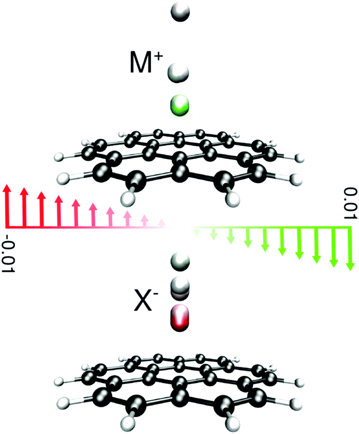 | ||
| Fig. 1 Representation of the studied systems; the ions are located on the top of the central hexagon of coronene and are color-coded according to the field at which the position was determined. Electric field vectors are presented in atomic units. Positive and negative values for the electric field merely denote the direction of the applied field; a positive value represents a direction that pushes cations towards the surface of the receptor and vice versa. | ||
The strength of the electric field was increased from zero either to maximum 0.01 au in each direction or to the field strength at which the complex dissociates, in 0.001 au intervals. In the low-field regime the structures were optimized in increments of 0.0001 au to make sure that all features of the shallow PES of the complexes are inspected.
To gain an insight into the importance of non-electrostatic factors in the solvent–solute interactions and the rearrangement of solvent cavity, the first solvation layer was modeled by adding six water molecules to our systems in the SMD continuum solvent model. Structures were optimized at three EEF strengths (0.0000, 0.0050, and 0.0100 au) at the M06-2X/6-311++G(2df,2p) computational level. A comprehensive bonding analysis of the nature of ion–receptor interactions within the context of quantum theory of atoms in molecules, QTAIM,89 was performed via the AIMAll90 package. For details of bonding analysis, see ESI.† The binding energies were calculated using eqn (1).
| BE⊥ = EFieldcomplex–FS − (EFieldion–PS + EFieldπ–system–PS) + QF·(R1 − R0) | (1) |
To account for the energy change associated with partial desolvation of the ions and the π-system in the implicit solvent model, the ions and the atoms of the π-system are replaced with dummy atoms to prevent solvation on the one side of the ion/π-system without affecting the electronic energy similar to the counterpoise correction method by Boys and Bernardi.91 The magnitude of the partial desolvation energy (PDE), see Section 3.1, is evaluated as the energy difference between the partially solvated ion–π-system and the fully solvated components.
3. Results and discussion
3.1. Implicit solvent models: alterations of the bond length, binding and partial desolvation energies
The most prominent effect of water on the ion–π systems is attenuating the ion–π interaction by solvation of the ion. Consequently the ion–π binding energy (BE) decreases and the distance between the ions and the surface of the π-receptor – the bond length (BL) – increases compared to those in a vacuum. Plotting the BL or BE versus the EEF strength reveals an interesting phenomenon that is the coexistence of two minima with respect to the ion–surface distance in the low-field regime for fluoride and lithium complexes, Fig. 2. This feature has not been identified in the previous studies in a vacuum68–71 or for the nonpolar solvents in the present study, see the ESI.†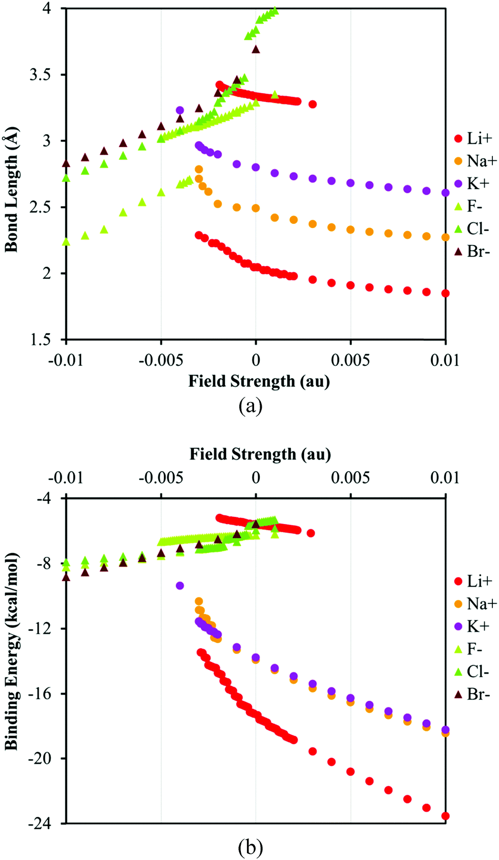 | ||
| Fig. 2 The plots of (a) bond length (the distance between ions and the center of symmetry in coronene) and (b) the binding energy of ion–π complexes versus the EEF strength. The positive and negative values of the EEF represent the different orientation of the field with respect to the ion–π system, see Fig. 1. | ||
Visualization of the solvent cavity for lithium or fluoride (Fig. 3) shows that in the low-electric-field limit the ions and the π-system are almost inside two different cavities loosely connected together but the cavity shape changes considerably in the high-field regime. This change is consistent with the desolvation process on the surface of the π-system. The absence of a double-minimum PES in nonpolar solvents or softer ions in water indicates that, in these cases, the ion–solvent interaction is less favored compared to the ion–π interaction. The observed trends are generally in agreement with experimental observations where the solvation shells of large and soft ions have been demonstrated to distort easier.75–79 However, our standard implicit solvent-model study is unable to correctly model the desolvation process for sodium cation which is known to be better solvated compared to fluoride.92
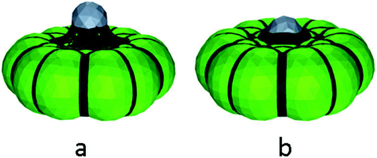 | ||
| Fig. 3 The solvation cavities for Li+·coronene complex at (a) EEF = 0.0010 au (bond length 3.32 Å) and (b) EEF = 0.0020 au (bond length 1.98 Å); in both cases the only one cavity is distinguishable, however, the cavity on the lithium side (top) has diminished significantly at higher field. The variation in the shape of the cavity can be interpreted in terms of solvation with different number of solvent molecules at various fields. | ||
Comparing the plots of BE or BL vs. EEF for the anions and cations unveils intrinsic differences, Fig. 2b. The binding energies of the anion–π complexes in the studied range of the field strength change less than those of the cation–π complexes. The difference between the magnitudes of the BEs of different anions, ca. 1 kcal mol−1, is comparable to the intrinsic DFT error limit; thus, it is hard to comment on the anion selectivity of the receptor at this theoretical level. Furthermore, the SMD and PCM models predict different trends of the BE variation for the anions. The SMD solvent model predicts that the relative BEs of the anion–π complexes decrease from the fluoride to the bromide in the low-field and unfavorable field direction (positive field region in Fig. 2). Among halides the bromide dissociates easier in the low-field limit whereas in the high-field region the bromide seems to have a higher BE with the π-system than chloride and fluoride. This trend is in contrast with the prediction of the PCM model, where fluoride remains more strongly bonded to the π-system than the other halides at all field strengths, Tables S2–S7 (ESI†). The difference between PCM and SMD can be rationalized regarding the fact that SMD model accounts for dispersion that is more considerable for bromide compared to its lighter counterparts. It is worth noting that except fluoride complexes, the binding energies of anion–receptor systems do not change significantly by changing their environment from vacuum to solvent. This trend can be explained by the rather non-electrostatic nature of anion–π interactions for anions.71,93
There is a good agreement between the BEs of the cation–π complexes computed using SMD and PCM solvent models. In general, the BE of the ion–π complexes increases in order from Li+ to K+, Fig. 2, but the receptor hardly discriminates between the sodium and potassium cations on the basis of our implicit solvent models. Lithium, the hardest cation, forms a second stable structure that corresponds to a more solvated ion interacting weakly with the receptor (in parallel to F−, Fig. 3).75 By increasing the field strength the interaction of Li+ and the π-system becomes more favorable and the solvent shell rearranges. Finally, the most notable difference between the anionic and cationic systems is that unlike anions, the binding energies of cation–receptor systems change considerably when the environment changes from vacuum to a polar solvent. The greater energy change is expected from the fact that cations are better solvated in water92 and the nature of cation–π interactions benefits more from electrostatic interactions, unlike anion–π interactions.71,93
The variations in the BE/BL values versus the field strength can be understood in more detail considering the variation in the partial desolvation energy, PDE, versus the EEF strength, Fig. 4. The PDE increases for all species as the EEF increases. The increase in the PDE is more pronounced for the harder ions than for the softer ones in agreement with experimental studies and the notion that the hard ions are better solvated than their soft counterparts.75–77,79 The trends in the PDE vs. EEF plot confirm the conclusions drawn on the basis of the variation in the BE/BL values regarding the role of the solvation. The change in the PDE for both hard ions (F− and Li+) can be attributed to a perturbation of the solvent cavity as the number of coordinated water molecules around ions decreases, Fig. 2. As the EEF in the favorable direction increases, it attenuates the ion–solvent interaction and pushes ions towards the π-system. Therefore, the interplay between the solvation and ion–π interaction energies determines the magnitude of the BE. For details of the bonding mechanism between the ions and the receptor; see the ESI.†
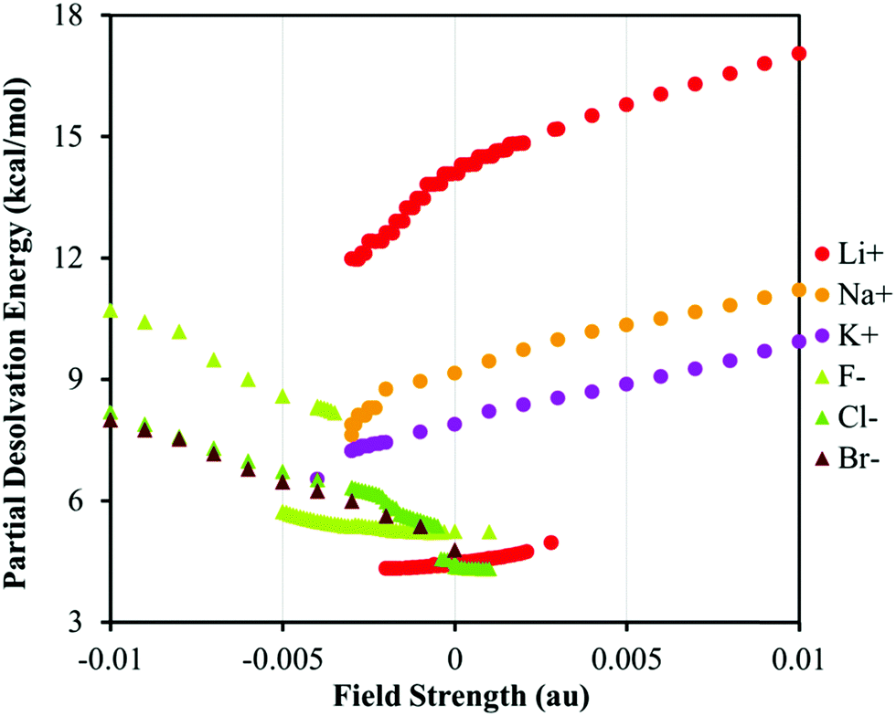 | ||
| Fig. 4 The plot of PDE versus the EEF strength for various systems. The positive and negative values of the EEF represent the switched orientation of the field with respect to the ion–π system, see Fig. 1. | ||
3.2 Rearrangement of the solvent shell studied using the cluster-continuum solvent model
Although the model systems used in this section contain a limited number of water molecules and the outer layers of the explicit solvent shells are neglected, they still provide an insight into the final stage of the solvent-shell rearrangement on the surface of an ion receptor.94The data summarized in Table 1 suggest that for three ions (Li+, Na+, and F−) the solvent shell undergoes a remarkable rearrangement in the studied range of electric field. Furthermore, addition of explicit water molecules increases the distance between the ions and the receptor at studied fields compared to the implicit solvent model. Under the field-free conditions the cluster-continuum model predicts that potassium has the shortest cation–π distance because it is not effectively solvated. This is consistent with a very recent study reported by Pham et al. on the interaction of NaCl/KCl with carbon nano-tubes.95
| Field (au) | Li+ | Na+ | K+ | F− | Cl− | Br− | |
|---|---|---|---|---|---|---|---|
| a Local minimum structure was not identified. | |||||||
| 0.0000 | Ion–receptor distance (Å) | 4.403 | 4.310 | 3.075 | 4.421 | 3.413 | 3.532 |
| Coordination no. | 6 | 6 | 4 | 6 | 5 | 6 | |
| 0.0050 | Ion–receptor distance (Å) | 4.084 | 2.573 | 2.851 | 2.813 | 3.316 | 3.454 |
| Coordination no. | 6 | 4 | 4 | 5 | 5 | 5 | |
| 0.0100 | Ion–receptor distance (Å) | 2.571 | 2.495 | 2.726 | 2.559 | 3.156 | —a |
| Coordination no. | 4 | 4 | 4 | 4 | 5 | —a | |
The difference between implicit and cluster-continuum models can be rationalized by the fact that ion–water interactions cannot be modeled merely by charge–dipole interactions. Even additional dispersion of the SMD model is insufficient for precise evaluation of water–solute interaction energy. An accurate model must include the effect of exchange–correlation between the ion–water as well as water–receptor molecules. This effect triggers polarization and fractional electron-sharing between ions, water, and receptors that are absent in the implicit models used in this study.
A strong EEF disturbs the arrangement of water molecules that are in the vicinity of the receptor; the water molecules tend to orient their dipoles along the applied field while interacting simultaneously with the ions. By changing the direction of the applied field, the orientation of water molecules changes from predominant O–H⋯π more towards lone-pair(O)⋯π interactions,96,97Fig. 5b vs. d.
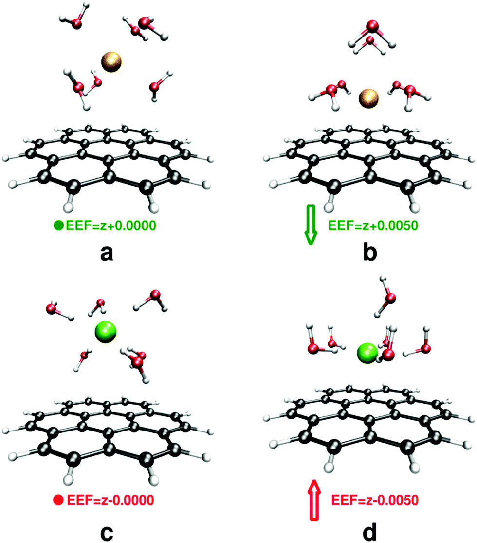 | ||
| Fig. 5 Rearrangement of water molecules around the ions, (a) and (b) for sodium and (c) and (d) for fluoride at EEF = 0 (left) and EEF = 0.005 au (right). All structures are fully optimized. Breaking the solvent shell after application of an EEF is evident for both ions. | ||
4. Conclusions and prospects
In the present work the influence of an external electric field on the ion–receptor interaction in water – modeled by implicit and cluster-continuum models – was studied. In this study we neglected the effect of dynamics of solution and the interactions between internal electric fields of ions present in the solution,98,99 which best describes an ideal ionic solution, and limited ourselves to understanding the factors governing the ion–solvent–receptor interactions.Implicit solvent models can describe the desolvation process the best for the hardest anion and cation investigated here (fluoride and lithium). These models show that the strong electric field forces the solvent shell of the ions to break and results in a direct contact between the ion and the receptor. However, if the electric field is not strong enough, an efficiently solvated ion interacts remotely with the receptor. Although, the SMD model partly accounts for the dispersion term in the solvent–solute interactions, it still fails to model solvated-ion–receptor complexes for sodium cations in spite of the known fact that sodium is better solvated than the fluoride in the vicinity of carbon-based electrodes.92 To investigate this issue explicit water molecules were added to the implicit model to account for the first solvent shell around the ions. By addition of explicit water molecules a fully-solvated sodium ion interacting with the receptor was identified.
In general, a full quantum mechanical treatment of the solute and at least the first solvation shell is necessary for obtaining a precise description of the ion–receptor interactions in the presence of an external electric field. This originates from the strong correlation effect on the solvent–solute–receptor interactions. It is worth emphasizing that we selected a coronene molecule as our model receptor system but it is known that the larger the receptor gets, the stronger the effect of exchange and correlation on ion–receptor interactions will be.69
Our previous work on the gas-phase and the present paper (see ESI†) on the neutral receptor suggest that the mechanism of the charge transfer between ions and receptors conforms to the Harpoon mechanism,100 however, addition of charge on the receptor may change this picture. This question along with the questions regarding the influence of the dynamics of the system will be answered in our subsequent works.
Acknowledgements
Authors thank to Luca Frediani, University of Tromsø, Norway, for his constructive comments. C. F.-N. thanks financial support from the SoMoPro II program – the research leading to this invention has acquired a financial grant from the People Program (Marie Curie action) of the Seventh Framework Program of EU according to the REA Grant Agreement No. 291782. This publication reflects only the author's views and the Union is not liable for any use that may be made of the information contained therein. This work was carried out under the project CEITEC 2020 (LQ1601) with financial support from the Ministry of Education, Youth and Sports of the Czech Republic under the National Sustainability Programme II. Computational resources were provided by the CESNET LM2015042 and the CERIT Scientific Cloud LM2015085, provided under the programme “Projects of Large Research, Development, and Innovations Infrastructures”.References
- M. Muruganathan, J. Sun, T. Imamura and H. Mizuta, Nano Lett., 2015, 15, 8176–8180 CrossRef CAS PubMed.
- Y. Tao, Q. Xue, Z. Liu, T. Zhang, X. Li, T. Wu, Y. Jin and L. Zhu, Sci. Adv. Mater., 2015, 7, 239–248 CrossRef CAS.
- M. Calvaresi, R. V. Martinez, N. S. Losilla, J. Martinez, R. Garcia and F. Zerbetto, J. Phys. Chem. Lett., 2010, 1, 3256–3260 CrossRef CAS.
- A. A. Arabi and C. F. Matta, Phys. Chem. Chem. Phys., 2011, 13, 13738–13748 RSC.
- M. E. Corrales, J. Gonzàlez-Vàzquez, G. Balerdi, I. R. Solà, R. de Nalada and L. Bañares, Nat. Chem., 2014, 6, 785–790 CrossRef CAS PubMed.
- Z. Li, H. Huang, T. Zhang, G. Zhang and F. Zhang, RSC Adv., 2015, 5, 22601–22608 RSC.
- B. J. Dutta and P. K. Bhattacharyya, Int. J. Quantum Chem., 2015, 115, 1459–1466 CrossRef CAS.
- H. Liu and J. Y. Lee, J. Phys. Chem. C, 2012, 116, 3034–3041 CAS.
- C. Chen, L. Miao, K. Xu, J. Yao, C. Li and J. Jiang, Phys. Chem. Chem. Phys., 2013, 15, 6431–6436 RSC.
- S. Sowlati-Hashjin and C. F. Matta, J. Chem. Phys., 2013, 139, 144101 CrossRef PubMed.
- S. Bubin, A. G. Russakoff and K. Varga, J. Phys.: Conf. Ser., 2013, 463, 012084 CrossRef.
- A. Palii, J. M. Clemente-Juan, B. Tsukerblat and E. Coronado, Chem. Sci., 2014, 5, 3598–3602 RSC.
- Y. Yamagata, Y. Imamura and H. Nakai, Chem. Phys. Lett., 2012, 530, 132–136 CrossRef CAS.
- T. Goswami and A. Misra, Chem. – Eur. J., 2014, 20, 13951–13956 CrossRef CAS PubMed.
- E. J. G. Santos and E. Kaxiras, Nano Lett., 2013, 13, 898–902 CrossRef CAS PubMed.
- G. Lee, G. Yang, A. Cho, J. W. Han and J. Kim, Phys. Chem. Chem. Phys., 2016, 18, 14198–14204 RSC.
- C. S. Liu, R. Jia, X.-J. Ye and Z. Zeng, J. Chem. Phys., 2013, 139, 034704 CrossRef PubMed.
- H. Hirao, H. Chen, M. A. Carvajal, Y. Wang and S. Shaik, J. Am. Chem. Soc., 2008, 130, 3319–3327 CrossRef CAS PubMed.
- S. Shaik, S. P. de Visser and D. Kumar, J. Am. Chem. Soc., 2004, 126, 11746–11749 CrossRef CAS PubMed.
- A. C. Aragonès, N. L. Haworth, N. Darwish, S. Ciampi, N. J. Bloomfield, G. G. Wallace, I. Diez-Perez and M. L. Coote, Nature, 2016, 531, 88–91 CrossRef PubMed.
- K. S. Novoselov, A. K. Geim, S. V. Morozov, D. Jiang, Y. Zhang, S. V. Dubonos, I. V. Grigorieva and A. A. Firsov, Science, 2004, 306, 666–669 CrossRef CAS PubMed.
- L. Huang, L. Massa and C. F. Matta, Carbon, 2014, 76, 310–320 CrossRef CAS.
- O. Ayyad, V. Ruiz and P. Gómez-Romero, Chem. Soc. Rev., 2015, 44, 1777–1790 RSC.
- B. Luo, S. Liu and L. Zhi, Small, 2012, 8, 630–646 CrossRef CAS PubMed.
- L. Dai, D. W. Chang, J.-B. Baek and W. Lu, Small, 2012, 8, 1130–1166 CrossRef CAS PubMed.
- D. M. Bhatt and C. O'Dwyer, Phys. Chem. Chem. Phys., 2015, 17, 4799–4844 RSC.
- C. Liu, Z. Yu, D. Neff, A. Zhamu and B. Z. Jang, Nano Lett., 2010, 10, 4863–4868 CrossRef CAS PubMed.
- M. F. El-Kady, V. Strong, S. Dubin and R. B. Kaner, Science, 2012, 335, 1326–1330 CrossRef CAS PubMed.
- J. R. Miller, R. A. Outlaw and B. C. Holloway, Science, 2010, 329, 1637–1639 CrossRef CAS PubMed.
- M. D. Stoller, S. Park, Y. Zhu, J. An and R. S. Ruoff, Nano Lett., 2008, 10, 3498–3502 CrossRef PubMed.
- Y. Huang, J. Liang and Y. Chen, Small, 2012, 8, 1805–1834 CrossRef CAS PubMed.
- H. Nishihara and T. Kyotani, Adv. Mater., 2012, 24, 4473–4498 CrossRef CAS PubMed.
- C. Liu, F. Li, L.-P. Ma and H. M. Cheng, Adv. Mater., 2010, 22, E28–E62 CrossRef CAS PubMed.
- S. Bose, T. Kuila, A. K. Mishra, R. Rajasekar, N. H. Kim and J. H. Lee, J. Mater. Chem., 2012, 22, 767–784 RSC.
- L. Britnell, R. V. Gorbachev, R. Jalil, B. D. Belle, F. Schedin, A. Mishchenko, T. Georgiou, M. I. Katsnelson, L. Eaves, S. V. Morozov, N. M. R. Peres, J. Leist, A. K. Geim, K. S. Novoselov and L. A. Ponomarenko, Science, 2012, 335, 947–950 CrossRef CAS PubMed.
- Y. M. Lin, A. Valdes-Garcia, S. J. Han, D. B. Farmer, I. Meric, Y. Sun, Y. Wu, C. Dimitrakopoulos, A. Grill, P. Avouris and K. A. Jenkins, Science, 2011, 332, 1294–1297 CrossRef CAS PubMed.
- C. Reiner-Rozman, M. Larisika, C. Nowak and W. Knoll, Biosens. Bioelectron., 2015, 70, 21–27 CrossRef CAS PubMed.
- P. Chuang, S.-C. Ho, L. W. Smith, F. Sfigakis, M. Pepper, C.-H. Chen, J.-C. Fan, J. P. Griffiths, I. Farrer, H. E. Beere, G. A. C. Jones, D. A. Ritchie and T.-M. Chen, Nat. Nanotechnol., 2015, 10, 35–39 CrossRef CAS PubMed.
- R. M. Penner and Y. Gogotsi, ACS Nano, 2016, 10, 3875–3876 CrossRef CAS PubMed.
- I. A. Hamed, M. A. Novotny, D. O. Wipf and P. A. Rikvold, Phys. Chem. Chem. Phys., 2010, 12, 2740–2743 RSC.
- M. V. Fedorov and R. M. Lynden-Bell, Phys. Chem. Chem. Phys., 2012, 14, 2552–2556 RSC.
- J. Vatamanu, L. Xing, W. Li and D. Bedrov, Phys. Chem. Chem. Phys., 2014, 16, 5174–5182 RSC.
- T. Méndez-Morales, J. Carrete, M. Pérez-Rodríguez, O. Cabeza, L. J. Gallego, R. M. Lynden-Bell and L. M. Varela, Phys. Chem. Chem. Phys., 2014, 16, 13271–13278 RSC.
- R. Jorn, R. Kumar, D. P. Abraham and G. A. Voth, J. Phys. Chem. C, 2013, 117, 3747–3761 CAS.
- K. Tasaki, J. Phys. Chem. B, 2005, 109, 2920–2933 CrossRef CAS PubMed.
- J. Vatamanu, O. Borodin and G. D. Smith, J. Phys. Chem. C, 2012, 116, 1114–1121 CAS.
- L. Xing, J. Vatamanu, O. Borodin, G. D. Smith and D. Bedrov, J. Phys. Chem. C, 2012, 116, 23871–23881 CAS.
- J. Zheng, Z. Ren, P. Guo, L. Fang and J. Fan, Appl. Surf. Sci., 2011, 258, 1651–1655 CrossRef CAS.
- D. Datta, J. Li and V. B. Shenoy, ACS Appl. Mater. Interfaces, 2014, 6, 1788–1795 CAS.
- R. E. Mapasha and N. Chetty, Comput. Mater. Sci., 2010, 49, 787–791 CrossRef CAS.
- P. V. C. Medeiros, F. de Brito Mota, A. J. S. Mascarenhas and C. M. de Castilho, Nanotechnology, 2010, 21, 115701 CrossRef PubMed.
- X. Fan, W. T. Zheng, J.-L. Kuo and D. J. Singh, ACS Appl. Mater. Interfaces, 2013, 5, 7793–7797 CAS.
- J. Song and B. Ouyang, ACS Appl. Mater. Interfaces, 2013, 5, 12968–12974 CAS.
- X. Fan, W. T. Zheng and J.-L. Kuo, ACS Appl. Mater. Interfaces, 2012, 4, 2432–2438 CAS.
- G. Wang, B. Wang, X. Wang, J. Park, S. Dou, H. Ahn and K. Kim, J. Mater. Chem., 2009, 19, 8378–8384 RSC.
- A. Buldum and G. Tetiker, J. Appl. Phys., 2013, 113, 154312 CrossRef.
- L.-J. Zhou, Z. F. Hou and L. M. Wu, J. Phys. Chem. C, 2012, 116, 21780–21787 CAS.
- H. Zhang, M. Zhao, X. He, Z. Wang, X. Zhang and X. Liu, J. Phys. Chem. C, 2011, 115, 8845–8850 CAS.
- M. Khantha, N. A. Cordero, L. M. Molina, J. A. Alonso and L. A. Girifalco, Phys. Rev. B: Condens. Matter Mater. Phys., 2004, 70, 125422 CrossRef.
- K. T. Chan, J. B. Neaton and M. L. Cohen, Phys. Rev. B: Condens. Matter Mater. Phys., 2008, 77, 235430 CrossRef.
- C.-K. Yang, Appl. Phys. Lett., 2009, 94, 163115 CrossRef.
- H. Zhang, Y. Xia, H. Bu, X. Wang, M. Zhang, Y. Luo and M. Zhao, J. Appl. Phys., 2013, 113, 044309 CrossRef.
- W. Koh, H. S. Moon, S. G. Lee, J. I. Choi and S. S. Jang, ChemPhysChem, 2015, 16, 789–795 CrossRef CAS PubMed.
- A. M. Garay-Tapia, A. H. Romero and V. Barone, J. Chem. Theory Comput., 2012, 8, 1064–1071 CrossRef CAS PubMed.
- R. Lu, D. Rao, Z. Meng, X. Zhang, G. Xu, Y. Liu, E. Kan, C. Xiao and K. Deng, Phys. Chem. Chem. Phys., 2013, 15, 16120–16126 RSC.
- K. Srinivasu and S. K. Ghosh, J. Phys. Chem. C, 2012, 116, 5951–5956 CAS.
- S. Lee, M. Lee and Y.-C. Chung, Phys. Chem. Chem. Phys., 2013, 15, 3243–3248 RSC.
- B. Peles-Lemli, D. Kánnár, J. C. Nie, H. Li and S. Kunsági-máté, J. Phys. Chem. C, 2013, 117, 21509–21515 CAS.
- C. Foroutan-Nejad and R. Marek, Phys. Chem. Chem. Phys., 2014, 16, 2508–2514 RSC.
- C. Foroutan-Nejad, M. Novák and R. Marek, J. Phys. Chem. C, 2015, 119, 5752–5754 CAS.
- M. Novak, C. Foroutan-Nejad and R. Marek, J. Chem. Theory Comput., 2016, 12, 3788–3795 CrossRef PubMed.
- A. Saenz, Phys. Rev. A: At., Mol., Opt. Phys., 2000, 61, 051402 CrossRef.
- A. Saenz, Phys. Rev. A: At., Mol., Opt. Phys., 2002, 66, 063407 CrossRef.
- D. S. Hecht, L. Hu and G. Irvin, Adv. Mater., 2011, 23, 1482–1513 CrossRef CAS PubMed.
- S. Baldelli, G. Mailhot, P. N. Ross and G. A. Somorjai, J. Am. Chem. Soc., 2001, 123, 7697–7702 CrossRef CAS PubMed.
- A. Yamakata, E. Soeta, T. Ishiyama, M. Osawa and A. Morita, J. Am. Chem. Soc., 2013, 135, 15033–15039 CrossRef CAS PubMed.
- A. Yamakata and M. Osawa, J. Am. Chem. Soc., 2009, 131, 6892–6893 CrossRef CAS PubMed.
- H. Keller, M. Saracino, H. M. T. Nguyen, T. M. T. Huyneh and P. Broekmann, J. Phys. Chem. C, 2012, 116, 11068–11076 CAS.
- A. Yamakata and M. Osawa, J. Phys. Chem. Lett., 2010, 1, 1487–1491 CrossRef CAS.
- H. Keller, M. Saracino, H. M. T. Nguyen and P. Broekmann, Phys. Rev. B: Condens. Matter Mater. Phys., 2010, 82, 245425 CrossRef.
- D. M. Cyr, B. Venkataraman and G. W. Flynn, Chem. Mater., 1996, 8, 1600–1615 CrossRef CAS.
- W. Mamdouh, H. Uji-I, J. S. Ladislaw, A. E. Dulcey, V. Percec, F. C De Schryver and S. De Feyter, J. Am. Chem. Soc., 2006, 128, 317–325 CrossRef CAS PubMed.
- M. Saracino, P. Broekmann, K. Gentz, M. Becker, H. Keller, F. Janetzko, T. Bredow, K. Wandelt and H. Dosch, Phys. Rev. B: Condens. Matter Mater. Phys., 2009, 79, 115448 CrossRef.
- M. N. Nair, C. Mattioli, M. Cranney, J.-P. Malval, F. Vonau, D. Aubel, J. L. Bubendorff, A. Gourdon and L. Simon, J. Phys. Chem. C, 2015, 119, 9334–9341 CAS.
- Y. Zhao and D. G. Truhlar, Theor. Chem. Acc., 2008, 120, 215–241 CrossRef CAS.
- J. Tomasi, B. Mennucci and R. Cammi, Chem. Rev., 2005, 105, 2999–3093 CrossRef CAS PubMed.
- A. V. Marenich, C. J. Cramer and D. G. Truhlar, J. Phys. Chem. B, 2009, 113, 6378–6396 CrossRef CAS PubMed.
- M. J. Frisch, G. W. Trucks, H. B. Schlegel, G. E. Scuseria, M. A. Robb, J. R. Cheeseman, G. Scalmani, V. Barone, B. Mennucci, G. A. Petersson, H. Nakatsuji, M. Caricato, X. Li, H. P. Hratchian, A. F. Izmaylov, J. Bloino, G. Zheng, J. L. Sonnenberg, M. Hada, M. Ehara, K. Toyota, R. Fukuda, J. Hasegawa, M. Ishida, T. Nakajima, Y. Honda, O. Kitao, H. Nakai, T. Vreven, J. A. MontgomeryJr, J. E. Peralta, F. Ogliaro, M. Bearpark, J. J. Heyd, E. Brothers, K. N. Kudin, V. N. Staroverov, T. Keith, R. Kobayashi, J. Normand, K. Raghavachari, A. Rendell, J. C. Burant, S. S. Iyengar, J. Tomasi, M. Cossi, N. Rega, J. M. Millam, M. Klene, J. E. Knox, J. B. Cross, V. Bakken, C. Adamo, J. Jaramillo, R. Gomperts, R. E. Stratmann, O. Yazyev, A. J. Austin, R. Cammi, C. Pomelli, J. W. Ochterski, R. L. Martin, K. Morokuma, V. G. Zakrzewski, G. A. Voth, P. Salvador, J. J. Dannenberg, S. Dapprich, A. D. Daniels, O. Farkas, J. B. Foresman, J. V. Ortiz, J. Cioslowski and D. J. Fox, Gaussian, 09, Revision D01, Gaussian, Inc, Wallingford CT, 2013 Search PubMed.
- R. F. W. Bader, Atoms in Molecules: A Quantum Theory, Oxford University Press, Oxford, 1990 Search PubMed.
- T. A. Keith, TK Gristmill Software AIMAll (Version 14.06.21), Overland Park KS, USA, 2014, http://aim.tkgristmill.com Search PubMed.
- S. F. Boys and F. Bernardi, Mol. Phys., 1970, 19, 553–566 CrossRef CAS.
- Z.-X. Luo, Y.-Z. Xing, S. Liu, Y.-C. Ling, A. Kleinhammes and Y. Wu, J. Phys. Chem. Lett., 2015, 6, 5022–5026 CrossRef CAS PubMed.
- C. Foroutan-Nejad, Z. Badri and R. Marek, Phys. Chem. Chem. Phys., 2015, 17, 30670–30679 RSC.
- D. Riccardi, H.-B. Guo, J. M. Parks, B. Gu, L. Liang and J. C. Smith, J. Chem. Theory Comput., 2013, 9, 555–569 CrossRef CAS PubMed.
- T. A. Pham, S. M. G. Mortuza, B. C. Wood, E. Y. Lau, T. Ogitsu, S. F. Buchsbaum, Z. S. Siwy, F. Fornasiero and E. Schwegler, J. Phys. Chem. C, 2016, 120, 7332–7338 CAS.
- Z. Badri, C. Foroutan-Nejad, J. Kozelka and R. Marek, Phys. Chem. Chem. Phys., 2015, 17, 26183–26190 RSC.
- J. Novotný, S. Bazzi, R. Marek and J. Kozelka, Phys. Chem. Chem. Phys., 2016, 18, 19472–19481 RSC.
- K. N. Chaki, S. Mandal, A. C. Reber, M. Qian, H. M. Saavedra, P. S. Weiss, S. N. Khanna and A. Sen, ACS Nano, 2010, 4, 5813–5818 CrossRef PubMed.
- S. Mandal, A. C. Reber, M. Qian, P. S. Weiss, S. N. Khanna and A. Sen, Acc. Chem. Res., 2013, 46, 2385–2395 CrossRef CAS PubMed.
- M. Rodríguez-Mayorga, E. Ramos-Cordoba, P. Salvador, M. Solà and E. Matito, Mol. Phys., 2016, 114, 1345–1355 CrossRef.
Footnote |
| † Electronic supplementary information (ESI) available. See DOI: 10.1039/c6cp05781k |
| This journal is © the Owner Societies 2016 |