Polaron spin filtering in an organic ferromagnetic polymer: a dynamics simulation†
Hui
Wang
a,
Yuan
Li
*a,
Dong-mei
Li
a,
Bin
Cui
a and
De-Sheng
Liu
*ab
aSchool of Physics, State Key Laboratory of Crystal Materials, Shandong University, Jinan 250100, People's Republic of China. E-mail: liyuan_sdu@mail.sdu.edu.cn; li_dm@sdu.edu.cn; cuibin@sdu.edu.cn; liuds@sdu.edu.cn
bDepartment of Physics, Jining University, Qufu 273155, People's Republic of China
First published on 16th November 2015
Abstract
We present a model study of the dynamic properties of a polaron in an organic ferromagnetic polymer by focusing on the spin correlation between the polymer backbone and the side radicals. The simulations are performed by using a tight-binding description coupled with a nonadiabatic dynamics method. We find that, in the presence of an external electric field, the polarons with both up and down spins can get trapped near the side radicals of the polymer chain unless the electric field is stronger than a critical field. However, the magnitudes of the critical electric field vary quite differently for the spin-up and spin-down polarons as a function of the number of side radicals in the polymer, leading to the exponential change of the range of the electric field within which the spin-filtering takes place. The range of the electric field increases nearly in a linear manner with the strength of the electron–lattice coupling as a result of the increase of the polaron binding energy. The impact of the strength of the spin correlation between the backbone and the side radicals on the polaron spin filtering is also discussed. These findings are expected to be useful for the design of organic-based spin filters.
Introduction
Spintronics, a field aiming at the development of the next generation of functional devices by exploiting electron spin, has become increasingly active in recent years. Organic materials are currently seen as compelling candidates for spintronic applications because of their unique advantages such as flexibility, low-cost and large-area fabrication, and weak spin–orbit and hyperfine interactions. In particular, organic ferromagnets (OFMs), a class of materials possessing both organic and ferromagnetic properties, have been widely investigated in both chemical synthesis and device fabrication.1–4 In general, OFMs can be classified into two categories. One is organic magnetic macromolecules containing transition-metal ions, such as Mn, Fe, Cr and V;5–7 these types of OFMs usually have stable magnetism and high Curie temperature.7 The other is OFMs with only purely organic elements (i.e., C, H, O, and N) in the molecule.2,8,9 Many of these materials have been realized by using spin radicals which are usually heterocycles containing an unpaired electron.8,10,11As functional materials, OFMs have been recently studied for potential device applications. Yoo et al. measured the spin-dependent electronic transport properties of V[TCNE]x through a Au/OFM/Au structure, and a magnetoresistance with a maximum value of about 2.5% was obtained.3 Li et al. also investigated the magnetoresistance properties of such a material by bridging it to magnetic electrodes, and a room-temperature magnetoresistance was observed when the Al2O3 barrier was used.12 Sugawara et al. investigated the spin-dependent transport properties of spin-polarized wire molecules (ESBN)ClO4 connected to gold nanoparticles, they found that the transport mechanisms were different when the temperature was above and below 30 K, and the phenomenon of magnetoresistance was also observed.4,13 In addition, several theoretical studies were also performed to investigate the magnetism and electronic structure of OFMs. For instance, Ovchinnikov et al. first discussed the ferromagnetic ordering in a low-dimensional organic substance to explain the magnetism in poly-BIPO by considering the ferromagnetic exchange in carbon systems.14 Fang et al. described the ground state energy level and spin configuration of the quasi-one-dimensional organic ferromagnetic polymers with the extended Su–Schrieffer–Heeger (SSH) model by considering the itineracy of π electrons, the strong electron–lattice interaction, and the electron-electron correlation; the phenomena of spin-splitting and spin density wave were obtained according to their calculations.15,16 Xie et al. found that the spin density wave and charge density wave are closely related to the sizes and dimensions of the organic ferromagnets.17 Furthermore, OFMs were also used to design functional devices. For instance, Wang18 and Hu et al.19 respectively designed a spin filter based on organic ferromagnetic polymers, and large spin polarization currents are obtained according to their calculation. Zhu et al. reported a molecular spin valve with large abnormal magnetoresistance by combining spin density functional theory with nonequilibrium Green's function techniques.20 Hu et al. reported the phenomena of both charge rectification and spin rectification through an organic spin diode based on organic magnetic/nonmagnetic co-oligomers.21
Different from the case of inorganic materials, the charge carriers in organic polymers are polarons consisting of a charge (electron or hole) coupled with a localized distortion of the polymer geometry as a result of the strong electron–lattice couplings. Typically, depending on the strength of the electron–lattice coupling, the size of a polaron can span from a few to dozens of lattice sites. The dynamic properties of polarons in organic polymers have been widely investigated by considering their formation, movement and dissociation processes.22,23 When an external electric field is applied, the polaron moves as a whole along the polymer chain, and the velocity will not exceed the sound velocity according to Basko's calculation with adiabatic dynamics simulations.24 Moreover, as pointed out by Johansson and Stafström in a nonadiabatic dynamics simulation, a step-like sonic to supersonic transition of the polaron velocity can be explicitly observed in a conjugated polymer chain.25 By using the time-dependent density matrix renormalization group method, Wu et al. investigated the dynamic properties of polarons in conjugated polymers and found that the velocity of polarons can be suppressed by the on-site Coulomb interaction.26 Furthermore, Wei and Xie et al. discussed the effect of the electric field mode on the dynamic process of polarons, and they concluded that a polaron can remain stable under a very strong electric field if the field was switched on slowly enough.27 More investigations by focusing on the effects of interchain couplings, impurities and disorders on the dynamic properties of polarons have also been recently reported in the literature.28–30
Most recently, a model describing the polaron properties in OFMs was proposed by Hu et al.31 It was found that the charge distribution of a polaron is highly asymmetric under spatial reflection while the spin distribution is nearly symmetric. It is noted that all these findings are based on only a static picture of polarons in OFMs. However, to better understand the charge and spin transport properties of these materials, the knowledge of the dynamic properties of polarons in the presence of external electric field is highly required. On the other hand, while polaron dynamics in organic polymers have been widely investigated, our understanding of the effects of the spin side radicals on polaron spin, in particular their dynamic behaviors, is actually very limited. Here, we present a simulation of the polaron dynamics in OFMs by using a model that well accounts for the spin degree of freedom of OFMs and the induced polarons. As will be shown, we obtain and analyze a spin-filtering behavior of the polaron dynamics in the OFM system, which has potential applications in organic ferromagnetic devices.
Model and methods
In our simulations, we consider a one-dimensional organic ferromagnetic polymer chain with side radicals such as poly-BIPO,2,8 as shown schematically in Fig. 1. The backbone of the system can be described by the well-known SSH model, and the spin correlation between the backbone and the side radicals can be formulated by a Heisenberg-like Hamiltonian. Thus, the total Hamiltonian of the system is written as:| H = He + HR-s + HL. | (1) |
Here, He represents the Hamiltonian of the π-electrons on the backbone and takes the form of:32
 | (2) |
For poly-BIPO-like organic ferromagnetic polymers, the ferromagnetic properties were inferred from the π electrons on the backbone and the nonbonding electrons on the side radicals.15–17,31 The second term in eqn (1) denotes the correlation between the spin of electrons on the backbone and that on the side radicals (see Fig. 1)
 | (3) |
![[S with combining right harpoon above (vector)]](https://www.rsc.org/images/entities/i_char_0053_20d1.gif) represents the spin operator on the corresponding sites, δn,i denotes a Kronecker delta function and the subscript i represents the sequence number of the site to which the side radical connected.
represents the spin operator on the corresponding sites, δn,i denotes a Kronecker delta function and the subscript i represents the sequence number of the site to which the side radical connected.
The last term in eqn (1) represents the lattice part of the Hamiltonian that contains both the potential and kinetic energies of the lattice sites.
 | (4) |
Based on the Hamiltonian of eqn (1), we simulate the dynamics of the system by using a nonadiabatic mixed quantum-classical method. In our calculations, the electronic wave function is expanded on the spin-dependent Wannier basis  , where μ describes the μth energy level and Zμ,n,s the probability amplitude of the state |ψμ〉 at the nth site with spin s. In this context, the evolution of the electronic states is obtained by solving the time-dependent Schrödinger equation:
 | (5) |
| Mü(t) = K(un+1(t) + un−1(t) − 2un(t)) + α{eiγA[ρn,n+1(t) − ρn−1,n(t)] + c·c}. | (6) |
 denotes the charge density matrix. The charge distribution of a polaron on the nth site at time t can be calculated by
 | (7) |
 | (8) |
 | (9) |
 ,
,  , and
, and  . The polaron velocity at time t is given by v(t) = [pc(t + Δt) − pc(t)]/Δt.
The values of parameters in the simulations are chosen as follows: t0 = 2.5 eV, α = 41 eV nm−1, K = 2100 eV nm−12, and M = 1349.14 eV fs2 A−2, which are relevant to poly-BIPO.19 A polymer chain with total lattice sites of N = 150 is used. While the model parameters are chosen to specifically describe poly-BIPO organic ferromagnetic polymers, the conclusions obtained in our study are expected to be qualitatively applicable to other organic polymers with similar structures where the antiferromagnetic correlations between the spin of electrons on the backbone and that on the side radicals are important.
Results and discussion
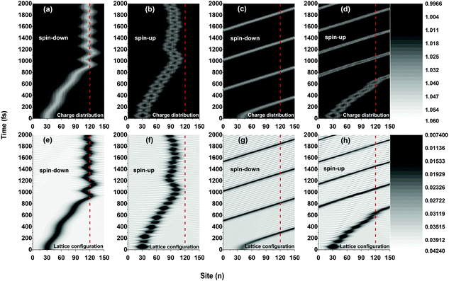
In our simulations, the external electric field is added smoothly to the system in terms of E(t) = E0·t/tc for 0 < t < tc and E(t) = E0 for t ≥ tc, where the critical time is chosen as tc = 75 fs. A polaron with specific spin (up or down) is initially set to center on the 30th site of the chain, and the spin of side radical electrons is set to spin up.Fig. 2 plots the results of the time evolution of the charge distribution and the smoothed lattice configuration of both spin-up and spin-down polarons moving in a polymer chain with only one side radical. It is seen that, due to the spin correlation between the backbone and the side radical, the motional behaviors of the polarons strongly depend on the type of their spin (up or down). When a weak electric field (E0 = 1.0 × 10⁻³ V nm−1) is applied, both spin-up and spin-down polarons are driven to move along the polymer chain (with a velocity of about 0.012 nm fs−1) and, when approaching the side radical (the 120th site), the polarons get trapped and no longer pass through the molecule which is in accordance with the threshold voltage in oligothiophene-type spin-polarized wire molecule based devices.4,13 Interestingly, the trapped polarons for both spin up and spin down vibrate around the side radical, as shown in Fig. 2(a), (b), (e), and (f). The difference for the two cases is that, during the vibrations, the spin-down polaron distributes on both sides of the 120th site while the spin-up polaron locates only on the left side, and the frequency of the vibration for the spin-down polaron is much higher than that of the spin-up polaron. However, when the applied electric field gets strong (E0 = 4.0 × 10⁻³ V nm−1), as shown in Fig. 2(c), (d), (g) and (h), the polarons for both cases can easily transport along the molecule without sign of obstacle by the side radical. In this situation, the polaron moves circularly under the periodic boundary condition with a constant velocity of about 0.041 nm fs−1. It is noted that, for both weak and strong electric fields, the polaron charge is always coupled to its lattice distortion during the movements, as shown in Fig. 2(e), (f), (g) and (h), indicating that the polarons remain stable throughout the simulations.
The polaron behaviors displayed in Fig. 2 are essentially as a result of the spin correlation between the backbone and the side radical, which changes the electron on-site energy of the site to which the side radical is connected. For the given values of parameters, the on-site energy rises for the spin-up electron and lowers for the spin-down one by about 0.2 eV, respectively, as shown in Fig. 3. As a result, the 120th site serves as a quantum well for the spin-down polaron but in contrast as a quantum barrier for the spin-up polaron. In this context, the spin-down polaron gets trapped by the quantum well when it reaches to the 120th site while the spin-up polaron gets blocked by the quantum barrier. It is noted that the quantum well has a size of only one site, which is too narrow to trap the whole spin-down polaron such that it distributes on both sides of the 120th site. When the electric field is weak, the trapped spin-down polaron does not have enough energy to escape from the quantum well and it thereby oscillates as a result of the competition between the trapping of the site and the driving of the electric field; the blocked spin-up polaron, however, always moves back and forth on the left side of the quantum barrier because of the rebound in the presence of the electric field. When the electric field is strong enough, the polarons in both cases achieve sufficient energy to overcome the quantum well/barrier and thereby transport smoothly along the polymer chain.
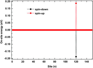 | ||
| Fig. 3 The on-site energy of electrons on each site. The value of the spin coupling parameter is Jf = 0.3t0, and the side radical is connected to the 120th site. | ||
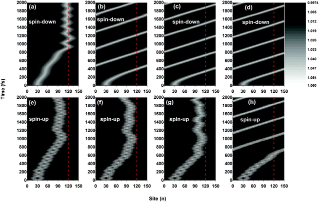
Although the dynamics of the polarons for both spins are significantly impacted by the side radical when the electric field is weak, the values of the critical electric field above which the polarons can move freely through the OFM molecule are different. For instance, as shown in Fig. 4, the spin-down polaron can pass through the OFM molecule when the external electric field is 2.0 × 10⁻³ V nm−1, while the spin-up polaron still remains trapped even when the driven electric field is increased to 3.0 × 10⁻³ V nm−1. Given the present values of parameters, we obtain that the critical electric field is about Ec = 1.4 × 10⁻³ V nm−1 for spin-down polarons and Ec = 3.5 × 10⁻³ V nm−1 for spin-up polarons, respectively. The results are excepted to explain the nonlinear I–V characteristics measured by Sugawara et al. in oligothiophene-type spin-polarized wire molecule based devices. When the driven electric field is weaker than the critical field, the center of the spin-up polaron is closer to the side radical position for a stronger electric field. Moreover, the vibration frequency of the spin-up polaron also increases with the electric field, as shown in Fig. 4(e), (f) and (g). It is important to note that, when the strength of the driven electric field falls into the range between that of the critical fields for the spin-up and spin-down polarons, only the spin-down polaron can pass through the OFM molecule, leading to a phenomenon of spin filtering in such a system. According to our simulations, the range of the electric field for spin filtering spans about ΔE = 2.1 × 10⁻³ V nm−1, which is consistent with the results obtained by using a static picture in ref. 19.
To further understand the phenomenon of spin filtering, we also calculated the total energy of the system during the time evolution of the polaron movement, and the results are shown in Fig. 5. In our simulations, the energy is calculated by Et(t) = Ee(t) + El(t), where Ee(t) = 〈φ(t)|H|ψ(t)〉 and  denote the energy of the electrons and lattice sites, respectively. When the polaron transports along the magnetic polymer chain, the system gets energy form the electric field. As a result, the total energy of the system increases during the polaron movement. On the other hand, the total energy of the system fluctuates as a result of the vibrations of the lattice sites. When a driven electric field of E0 = 1.5 × 10⁻³ V nm−1 is applied, the spin-down polaron can easily pass through the magnetic polymer molecule and the total energy of the system rises slightly throughout the transport. In the case of the spin-up polaron, the total energy of the system first increases in a way similar to the case of the spin-down polaron. When the spin-up polaron is closer to the side radical, the polaron level is lifted due to the spin correlation between electrons on the backbone and the side radicals. Furthermore, as the lattice sites vibrate more intensively, and the total energy of the system increases rapidly. As such, the spin-up polaron can no longer get enough energy from the electric field to move forward in this situation. For instance, when the center of the spin-up polaron moves to the 105th site, the spin-up polaron is blocked and the total energy of the system is about 10 eV higher than the case of the spin-down polaron.
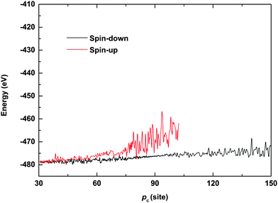 | ||
| Fig. 5 Total energy of the system as a function of the polaron center position. The driven electric field is E0 = 1.5 × 10⁻³ V nm−1. | ||
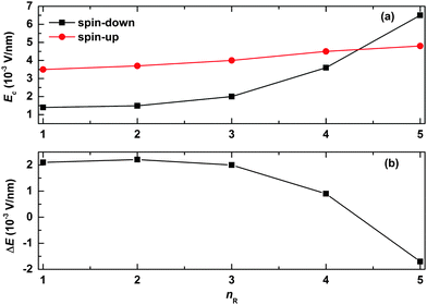
We now turn to explore the effects of the width of the quantum well/barrier on the spin-filtering properties. The results are shown in Fig. 6. In our simulations, the width of the quantum well/barrier is tuned by changing the number of the successively arranged side radicals in the polymer chain. As seen from Fig. 6(a), the values of the critical electric field are found to increase slowly and almost linearly for the spin-up polaron but nearly exponentially for the spin-down polaron as a function of nR. This is due to the fact that, in the case of the spin-up polaron, the width of the quantum barrier becomes larger with increasing nR such that it is more difficult for the polaron to get across; in the case of the spin-down polaron, more parts of the polaron get trapped by the quantum well such that the critical electric field increases exponentially with nR. As a result, the range of the electric field for spin filtering decreases almost exponentially with nR, as shown in Fig. 6(b). Interestingly, it is noted that only the spin-up polaron can pass through the OFM molecule when the value of nR is large enough.
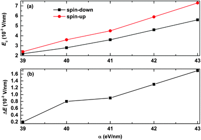
We also consider the effects of the electron–lattice coupling strength on the polaron transport, and the results are shown in Fig. 7. It is found that the values of the critical electric field for both the spin-up and spin-down polarons increase almost in a linear manner as a function of α, as seen from Fig. 7(a). However, as Ec for the spin-up polaron increases faster than that for the spin-down polaron, the range of the electric field for spin filtering also increases as a function of the strength of the electron–lattice coupling. As seen from Fig. 7(b), the range of the electric field for spin filtering is about ΔE = 0.2 × 10⁻³ V nm−1 for a relatively weak electron–lattice coupling of α = 39 eV nm−1, and it turns to ΔE = 1.7 × 10⁻³ V nm−1 when the value of α increases to 43 eV nm−1. These results suggest that OFMs with stronger electron–lattice coupling are more conducive to polaron spin filtering.
To understand the findings presented in Fig. 7, we calculated the binding energy of the spin dependent polarons with different strengths of the electron–lattice coupling. The polaron binding energy is defined as εps = ε0s − ε1s,33 where ε1s and ε0s denote the total energy of the system before and after the dissociation of the polaron, respectively, and the subscript s represents the spin index. As shown in Fig. 8, the binding energy of both spin-up and spin-down polarons increases almost linearly with the strength of the electron–lattice coupling. The binding energy of the spin-up polaron increases from 0.06 eV to 0.1 eV while it increases from 0.05 eV to about 0.09 eV for the spin-down polaron when α increases from 39 eV nm−1 to 43 eV nm−1. As a more stable polaron is harder to be driven by the electric field, it is more difficult for the polaron to overcome the quantum well/barrier when increasing the strength of the electron–lattice coupling. We also find that the velocity of the motional polaron decreases from 0.052 nm fs−1 to nearly 0.008 nm fs−1 when the value of α increases from 39 eV nm−1 to 43 eV nm−1. It is noted that, given the same values of parameters, the binding energy for the spin-up polaron is always higher than that for the spin-down polaron. As a result, the value of the critical electric field for the spin-up polaron increases faster than that for the spin-down polaron.
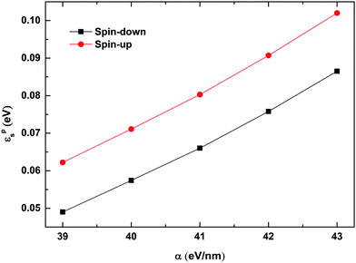 | ||
| Fig. 8 Binding energy of spin-up and spin-down polarons as a function of α. The value of the spin coupling parameter is Jf = 0.3t0, and the number of side radicals is nR = 4. | ||
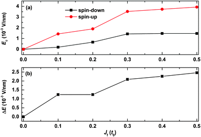
We finally discuss how the strength of the spin correlation between the backbone and the side radical impacts the spin filtering, and the results are shown in Fig. 9. It is seen that the values of the critical electric field for both spin-up and spin-down polarons first increase rapidly and then turn to almost saturate as a function of Jf. For instance, the value of the critical electric field increases from 0 to about 1.4 × 10⁻³ V nm−1 for the spin-down polaron while it increases from 0 to nearly 3.5 × 10⁻³ V nm−1 for the spin-up polaron as a function of Jf increasing from 0 to 0.3t0. When Jf is larger than 0.3t0, the values of the critical field for both the spin-up and spin-down polarons increase very slightly as a function of Jf. As a result, the range of the electric field for spin filtering first increases with Jf and then it increases slightly when the value of Jf is larger than 0.3t0, as shown in Fig. 9(b). These results indicate that the polaron spin filtering can be improved when improving the strength of the spin correlation between the backbone and the side radicals.
Conclusion
In summary, we have simulated the dynamic properties of polarons in an organic ferromagnetic polymer chain by considering the spin correlation between the polymer backbone and the ferromagnetic side radicals. We find that a quantum barrier (quantum well) for spin-up (spin-down) polarons near the side radical can be created as a result of the lifting (lowering) of the electron on-site energy caused by the spin correlation. As a result, the motion of the polarons for both spins is impeded near the side radical when the applied electric field is weaker than a critical field. The value of the critical electric field is found to be markedly influenced by the width of the quantum barrier (or the quantum well). Importantly, at some ranges of the electric field, we find that only the polarons with one specific spin orientation (up or down) can pass through the ferromagnet molecule, which leads to a polaron spin-filtering phenomenon in the studied system. Our findings are expected to be useful for guiding the design of organic-based spin filter devices.Acknowledgements
This work was supported by the Natural Science Foundation of China (Grant No. 11374183, 11574118, 21473102, 11404188).References
- J. S. Miller, A. J. Epstein and W. M. Reiff, Science, 1988, 240, 40–47 CAS.
- Y. V. Korshak, T. V. Medvedeva, A. A. Ovchinnikov and V. N. Spector, Nature, 1987, 326, 370–372 CrossRef CAS.
- J. W. Yoo, R. S. Edelstein, D. M. Lincoln, N. P. Raju, C. Xia, K. I. Pokhodnya, J. S. Miller and A. J. Epstein, Phys. Rev. Lett., 2006, 97, 247205 CrossRef PubMed.
- P. Nickels, M. M. Matsushita, M. Minamoto, S. Komiyama and T. Sugawara, Small, 2008, 4, 471–475 CrossRef CAS PubMed.
- K. Inoue, T. Hayamizu, H. Iwamura, D. Hashizume and Y. Ohashi, J. Am. Chem. Soc., 1996, 118, 1803–1804 CrossRef CAS.
- B. B. Kaul and G. T. Yee, Polyhedron, 2001, 20, 1757–1759 CrossRef CAS.
- J. M. Manriquez, T. Y. Gordon, R. S. McLean, A. J. Epstein and J. S. Miller, Science, 1991, 252, 1415–1417 CAS.
- Y. Cao, P. Wang, Z. Hu, S. Li, L. Zhang and J. Zhao, Synth. Met., 1988, 27, 625–630 CrossRef.
- A. Rajca, J. Wongsriratanakul and S. Rajca, Science, 2001, 294, 1503–1505 CrossRef CAS PubMed.
- Y. A. Katulevskii, M. A. Magrupov and A. A. Muminov, Phys. Status Solidi A, 1991, 127, 223–229 CrossRef CAS.
- T. Sugano, S. J. Blundell, T. Lancaster, F. L. Pratt and H. Mori, Phys. Rev. B: Condens. Matter Mater. Phys., 2010, 82, 180401 CrossRef.
- B. Li, M. Zhou, Y. Lu, C.-Y. Kao, J.-W. Yoo, V. N. Prigodin and A. J. Epstein, Org. Electron., 2012, 13, 1261–1265 CrossRef CAS.
- T. Sugawara, M. Minamoto, M. M. Matsushita, P. Nickels and S. Komiyama, Phys. Rev. B: Condens. Matter Mater. Phys., 2008, 77, 235316 CrossRef.
- A. A. Ovchinnikov and V. N. Spector, Synth. Met., 1988, 27, 615–624 CrossRef.
- Z. Fang, Z. L. Liu and K. L. Yao, Phys. Rev. B: Condens. Matter Mater. Phys., 1994, 49, 3916–3919 CrossRef.
- Z. Fang, Z. L. Liu, K. L. Yao and Z. G. Li, Phys. Rev. B: Condens. Matter Mater. Phys., 1995, 51, 1304–1307 CrossRef CAS.
- S. J. Xie, J. Q. Zhao, J. H. Wei, S. G. Wang, L. M. Mei and S. H. Han, Europhys. Lett., 2000, 50, 635 CrossRef CAS.
- W. Z. Wang, Phys. Rev. B: Condens. Matter Mater. Phys., 2006, 73, 235325 CrossRef.
- G. Hu, Y. Guo, J. Wei and S. Xie, Phys. Rev. B: Condens. Matter Mater. Phys., 2007, 75, 165321 CrossRef.
- L. Zhu, K. L. Yao and Z. L. Liu, Appl. Phys. Lett., 2010, 96, 082115 CrossRef.
- G. Hu, K. He, S. Xie and A. Saxena, J. Chem. Phys., 2008, 129, 234708 CrossRef PubMed.
- C. Q. Wu, Y. Qiu, Z. An and K. Nasu, Phys. Rev. B: Condens. Matter Mater. Phys., 2003, 68, 125416 CrossRef.
- S. V. Rakhmanova and E. M. Conwell, Synth. Met., 2000, 110, 37–45 CrossRef CAS.
- D. M. Basko and E. M. Conwell, Phys. Rev. Lett., 2002, 88, 056401 CrossRef CAS PubMed.
- A. A. Johansson and S. Stafström, Phys. Rev. B: Condens. Matter Mater. Phys., 2004, 69, 235205 CrossRef.
- H. Zhao, Y. Yao, Z. An and C. Q. Wu, Phys. Rev. B: Condens. Matter Mater. Phys., 2008, 78, 035209 CrossRef.
- X. Liu, K. Gao, J. Fu, Y. Li, J. Wei and S. Xie, Phys. Rev. B: Condens. Matter Mater. Phys., 2006, 74, 172301 CrossRef.
- Å. Johansson and S. Stafström, Phys. Rev. Lett., 2001, 86, 3602–3605 CrossRef PubMed.
- Y. H. Yan, Z. An and C. Q. Wu, Eur. Phys. J. B, 2004, 42, 157–163 CrossRef CAS.
- X. J. Yuan, D. M. Li, S. Yin, K. Gao, B. Cui and D. S. Liu, Org. Electron., 2012, 13, 2094–2103 CrossRef CAS.
- G. C. Hu, H. Wang, J. F. Ren, S. J. Xie and C. Timm, Org. Electron., 2014, 15, 118–125 CrossRef CAS.
- Y. Li, X. J. Liu, J. Y. Fu, D. S. Liu, S. J. Xie and L. M. Mei, Phys. Rev. B: Condens. Matter Mater. Phys., 2006, 74, 184303 CrossRef.
- Y. Li, K. Gao, Z. Sun, S. Yin, D. S. Liu and S. J. Xie, Phys. Rev. B: Condens. Matter Mater. Phys., 2008, 78, 014304 CrossRef.
Footnote |
| † Electronic supplementary information (ESI) available. See DOI: 10.1039/c5cp05789b |
| This journal is © the Owner Societies 2016 |


