Photophysics of Auramine-O: electronic structure calculations and nonadiabatic dynamics simulations†
Bin-Bin
Xie
,
Shu-Hua
Xia
,
Xue-Ping
Chang
and
Ganglong
Cui
*
Key Laboratory of Theoretical and Computational Photochemistry, Ministry of Education, College of Chemistry, Beijing Normal University, Beijing 100875, China. E-mail: ganglong.cui@bnu.edu.cn
First published on 6th November 2015
Abstract
Diphenylmethane dyes are very useful photoinduced molecular rotors; however, their photophysical mechanisms are still elusive until now. In this work, we adopted combined static electronic structure calculations (MS-CASPT2//CASSCF) and trajectory-based surface-hopping dynamics simulations (OM2/MRCI) to study the S1 excited-state relaxation mechanism of a representative diphenylmethane dye Auramine-O. On the basis of the optimized S1 minima and the computed emission bands, we have for the first time assigned experimentally proposed three transient states (i.e. S1-LE, S1-I1 or S1-I2, and S1-II). Mechanistically, upon irradiation to the S1 state, the system first relaxes to the locally excited S1 minimum (S1-LE). Starting from this point, there exist two kinds of relaxation paths to S1-II. In the sequential path, the system first evolves into S1-I1 or S1-I2 and then runs into S1-II; in the concerted one, the system, bypassing S1-I1 and S1-I2, directly runs into S1-II. In addition, the system can decay to the S0 state in the vicinity of three S1/S0 conical intersections i.e. S1S0-I1, S1S0-I2, and S1S0-II. In the S1 dynamic simulations, 54% trajectories decay to the S0 state via S1S0-II; the remaining trajectories are de-excited to the S0 state via S1S0-I1 (11%) and S1S0-I2 (35%). Our present theoretical investigation does not support the experimentally proposed S1 excited-state hypothesis that the intramolecular rotation of the two dimethyl groups around the C–N bond is responsible for the rapid decay of the emission band at about 500 nm; instead, it should be heavily interrelated with the rotation of the two dimethylanilino groups. Finally, this work provides important mechanistic insights into similar diphenylmethane dyes.
Introduction
Due to their utility as molecular rotors, di- and tri-phenylmethane dyes such as malachite green, crystal violet, ethyl violet, and brilliant green have attracted a lot of experimental attention on their photophysical and photochemical properties.1–25 In comparison, theoretical studies on these molecular rotors were rarely reported in the past decades.Auramine-O, a representative diphenylmethane dye in Fig. 1, shows similar excited-state relaxation dynamics as has been reported for tri-phenylmethane dyes, especially its ultrafast photoinduced intramolecular conformational changes.26–36 In the beginning, three important but different models were separately postulated by Oster and Nishijima,37 Forster and Hoffmann,38 and Bagchi, Fleming, and Oxtoby39 to study the effect of viscosity on quantum yields and the barrierless torsional motion of phenyl groups that leads to radiationless decay to the ground state. However, all these models can only describe a single-exponential excited-state relaxation behavior. Later, Martine and Glasbeek questioned the single-exponential models on the basis of observing nonexponential excited-state behavior and proposed an adiabatic coupling model involving a locally emissive excited state and a nonemissive excited state.40,41 Hirose et al. believed that not only solvent viscosity but also solvation dynamics affect the excited-state relaxation dynamics of Auramine-O.42 Meech and coworkers proposed that in aqueous solutions, solvation rather than solvent viscosity promotes a facile barrierless formation of a charge-transfer state and decides the excited-state relaxation.43,44 Singh et al. investigated Auramine-O using sub-picosecond time-resolved absorption spectroscopic techniques in aprotic and alcoholic solvents.45,46 They found two different stimulated emission bands at ca. 715 and 830 nm and suggested that there are two transition states involved in the excited-state relaxation. These findings are opposite to the widely accepted barrierless models. This is as well supported by Sen and Rafiq using time resolved femtosecond fluorescence measurements, in which an unexpectedly large fluorescence lifetime and multi-exponential transients in chloroform are observed.47 They also found that Auramine-O has eight times larger fluorescence quantum yield in chloroform than in methanol and that the torsional motion of the dimethylanilino groups occurs in 1.5 ps in methanol and 14.2 ps in chloroform. More recently, Erez et al. employed steady-state and time-resolved optical techniques to study the short-time excited-state decay dynamics of Auramine-O with a duration of about 150–300 fs in several solutions at room temperature.48,49 They found that its excited-state behavior could be divided into three time steps. The shortest decay time constant is associated with a strong emission with a band maximum at about 500 nm, which is attributed to the twisted motion of the dimethylamino group of the two anilines of Auramine-O. The second time constant is attributed to the rapid decay of the fluorescence band, which can be further red-shifted from about 510 nm to 550 nm in hydrogen-bonding solvents. The third time constant is related to a rather long decay of a dark state, about 10–20 ps in hydrogen-bonding liquids with medium viscosity. To summarize, experimentally, there exist a few ambiguous even paradoxical viewpoints on the photophysical mechanism of Auramine-O. For example, whether the torsional motion of the dimethylanilino groups is barrierless in the S1 state? What are the geometric and electronic structures for the transient states observed in experiments? What are the intrinsic S1 excited-state deactivation paths? Obviously, answering these atomistic mechanistic details calls for high-level ab initio electronic structure calculations, even the reliable nonadiabatic dynamics simulations.
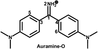 | ||
| Fig. 1 Molecular structure of the diphenylmethane dye Auramine-O. Also shown are the atomic labeling and the dihedral angles ϕ1(N2C1C3C5), ϕ2(N2C1C4C6), and ϕ3(C3C1C4N2). | ||
However, to the best of our knowledge, there are only few theoretical studies reported until now for excited-state properties of Auramine-O. Olsen proposed a four-electron, three-orbital model for low-energy electronic structures of several di- and tri-phenylmethane dyes including Auramine-O.31 Using DFT and TDDFT methods, Singh et al. obtained a ground state minimum and a transient state with the emission maximum at 831 nm.45 But, they did not obtain the other transient states proposed experimentally. Sen and Pafiq employed the same computational methods to scan the S1 and S0 potential energy surfaces of Auramine-O with respect to the rotation of the dimethylanilino rings.47 In addition, they suggested a funnel for the S1 excited-state radiationless decay to the ground state taking into account of the small S1–S0 energy gap.
In this work, we first employed the complete active space self-consistent field (CASSCF) and its second-order perturbation (CASPT2) methods to explore the S1 excited-state minima, conical intersections, and potential energy profiles relevant to the excited-state decay. On the basis of the results, we propose our S1 excited-state deactivation model. Finally, we use the semiempirical OM2/MRCI-based nonadiabatic dynamics simulations to verify our physical model. This work presents the first effort to systematically study the S1 excited-state deactivation pathways of Auramine-O using combined high-level electronic structure calculations and nonadiabatic dynamics simulations, setting the stage for studying the photophysics of other similar diphenylmethane dyes in near future.
Simulation details
Ab initio calculations
The ground-state conformer of Auramine-O is first optimized using the DFT method50 with the B3LYP exchange–correlation functional.51–54 Minima, conical intersections, and linearly interpolated internal coordinate (LIIC) paths are computed using the state-averaged complete active space self-consistent field (SA-CASSCF) method in which equal state weights are used for the S1 and S0 states. In the SA-CASSCF computations, the active space of 10 electrons in 8 orbitals is employed, which is referred to as SA-CASSCF(10,8) hereinafter. Since CASSCF theory is unable to provide sufficient correlation energy, the multi-state complete active space 2nd-order perturbation approach (MS-CASPT2)55,56 is exploited to re-evaluate the energies of all optimized structures and LIIC paths. In the MS-CASPT2 computations, the Cholesky decomposition technique with unbiased auxiliary basis sets is used for accurate two-electron integral approximations;57 the ionization potential-electron affinity (IPEA) shift of 0.0 is used;58 the imaginary shift technique (0.2 au) is employed to avoid intruder-state issues.59Vertical excitation energies at Franck–Condon points are also calculated using the MS-CASPT2, TD-B3LYP, and TD-CAM-B3LYP methods.60,61 6-31G and 6-31G* basis sets are employed for all geometry optimizations and single-point energy computations, respectively.62–65 DFT and TD-DFT calculations are carried out using GAUSSIAN09;50,60,66 SA-CASSCF optimizations for conical intersections are performed using MOLPRO2012;67 all SA-CASSCF computations for minima and LIIC paths and MS-CASPT2 computations are conducted using MOLCAS8.0.68,69
Semiempirical methods
All semiempirical calculations were performed using the OM2/MRCI method as implemented in the MNDO99 code.70–73 During geometry optimizations and dynamics simulations, all required energies, gradients and nonadiabatic coupling elements were computed analytically. Minimum-energy conical intersections were optimized using the Lagrange–Newton approach.74,75In the OM2/MRCI calculations, the restricted open-shell HF formalism was applied in the self-consistent field (SCF) treatment. The active space in the MRCI calculations included 12 electrons in 12 orbitals (see ESI,† Fig. S1). In terms of the SCF configuration it comprised five highest doubly occupied orbitals, two singly occupied orbitals, and five lowest unoccupied orbitals. For the MRCI treatment, three configuration state functions were chosen as references, namely the SCF configuration and the two closed-shell configurations derived therefrom (i.e., all singlet configurations that can be generated from the HOMO and the LUMO of the closed-shell ground state). The MRCI wavefunction was built by allowing all single and double excitations from these three references.
Nonadiabatic dynamics
The S1 nonadiabatic dynamics were studied by performing 1 ps OM2/MRCI trajectory surface-hopping simulations. The initial atomic coordinates and velocities for the S1 photodynamics simulations were randomly selected from a 5 ps NVT (T = 300 K) ground-state trajectory. The excited state dynamic runs were then chosen according to the computed S0–S1 transition probabilities; configurations with very small S0–S1 transition dipole moments were not sampled. A total of 200 surface-hopping trajectories were run for the S1 photodynamics, with all relevant energies, gradients, and nonadiabatic coupling vectors being computed on-the-fly as needed. For points with an energy gap of less than 10 kcal mol−1, the fewest-switches criterion was applied to decide whether to hop. The time step was chosen to be 0.1 fs for the nuclear motion and 0.0005 fs for the electronic propagation. The unitary propagator evaluated at mid-point was used to propagate the electronic motion. The translational and rotational motions were removed in each step. The empirical decoherence correction (0.1 au) proposed by Granucci et al. was employed.76 The final evaluations were done for 186 trajectories that finished successfully in the S1 photodynamics and that satisfied our energy continuity criterion (no change greater than 30 kcal mol−1 between any two consecutive MD steps). Further technical details were given in previous publications.25,77–98Results and discussion
S0 structure and vertical excitation energies
By using the OM2/MRCI and SA-CASSCF methods, we have optimized the ground-state conformers of Auramine-O. All these computations give a similar equilibrium structure shown in Fig. 3. The stable S0 conformer is almost in C2 symmetry. Its C1–C3 and C1–C4 bond lengths are 1.439 and 1.440 Å at the SA-CASSCF level, its two dihedral angles ϕ1(N2C1C3C5) and ϕ2(N2C1C4C6) are computed to be 29.8° and 29.2° at the same computational level as well.Table 1 collects the computed vertical excitation energies to S1 at the S0 minimum S0. Compared with the experimental value measured in methanol solution,49 TD-CAM-B3LYP and MS-CASPT2 computations overestimate and underestimate the S0 → S1 vertical excitation energy, respectively; but, TD-B3LYP computations fortuitously give very good agreement. Our current OM2/MRCI computations give a reasonably accurate number: the vertical excitation energy to the S1 state is 0.4 eV lower than the experimental value.49
Analysis of electronic configuration states in the CASPT2 computations illustrates that the S1 vertical electronic excitation mainly originates from HOMO → LUMO as shown in Fig. 2 (weight: 0.67) and HOMO−1 → LUMO (0.16). The S1 electronic state at the Franck–Condon point has clear charge-transfer character from the phenyl to methaniminium group. Charge-transfer electronic transition is usually associated with the remarkable change in the permanent electronic dipole moments, in either magnitudes or directions. In our OM2/MRCI computations, electronic dipole moments at the S0 minimum S0 are computed to be 2.2 Debye for the S0 state and 1.2 Debye for the S1 state; thus, the S1 state is of charge-transfer character. It is in line with the point of view proposed by Singh et al.45 that the emissive state is expected to be less polar than the ground state due to the neutralization of the positive charge of the nitrogen atom as a result of intramolecular charge transfer from the dimethylanilino to methaniminium or imidocarbonyl group.
 | ||
| Fig. 2 Canonical molecular orbitals related to the S0 → S1 (HOMO → LUMO) electronic transition at the Franck–Condon point at the OM2/MRCI level. | ||
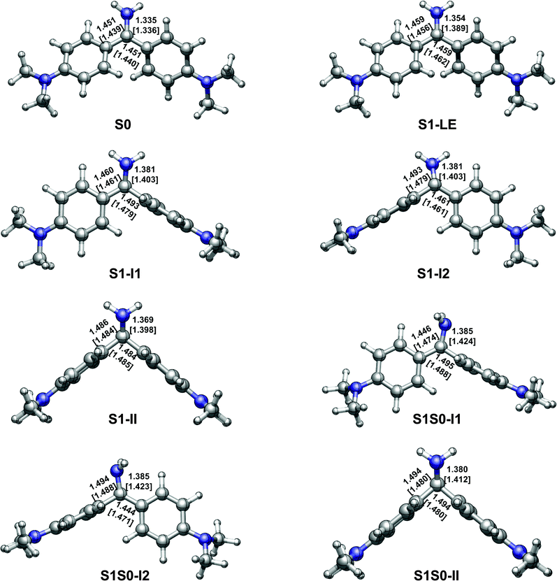 | ||
| Fig. 3 OM2/MRCI [SA-CASSCF] optimized S0 and S1 minima and S1/S0 conical intersections. See Table 2 for their relative energies and Fig. 1 for the dihedral angles ϕ1(N2C1C3C5), ϕ2(N2C1C4C6), and ϕ3(C3C1C4 N2). | ||
S1 minima
With the OM2/MRCI and SA-CASSCF methods, three kinds of minima are optimized in the S1 state, which are referred to as S1-LE, S1-I1, S1-I2, and S1-II in Fig. 3. Overall, S1-LE is structurally similar to the S0 minimum S0 except for a little different bond lengths and dihedral angles. In comparison, S1-II changes a lot in structure. At the OM2/MRCI and SA-CASSCF levels, the corresponding ϕ1 and ϕ2 dihedral angles are ϕ1 = 127.8° and 128.1°, and ϕ2 = 33.9° and 34.9°; the C1–C3 and C1–C4 bond lengths are nearly same as each other, 1.486 and 1.484 Å…, and 1.484 and 1.485 Å…, respectively. Its dihedral angle ϕ3 is also rotated to about 137.0° and 138.9° as the central carbon atom changes its hybridization pattern from sp2 to sp3. In addition, we have also optimized another pair of S1 minima i.e. S1-I1 and S1-I2 in Fig. 3. In these two structures, one aminophenyl group is almost perpendicular to the other aminophenyl and amino groups, for example, ϕ2 = 103.6° (101.1°) for S1-I1 and ϕ1 = 74.6° (77.2°) for S1-I2 at the OM2/MRCI (SA-CASSCF) level. Energetically, these four S1 minima are close to each other in the order of S1-LE, S1-I1, S1-I2, and S1-II, they are 62.5 (60.0), 62.2 (68.1), 62.2 (68.1), and 60.4 (64.5) kcal mol−1 at the OM2/MRCI (MS-CASPT2) level. However, their importance in the photodynamics of Auramine-O is very different due to the ease of access to these structures (see the following).In experiments of steady-state absorption and emission spectra in different solutions, Palit and coworkers found an important spectroscopic feature that there is a weak but long tail in the main fluorescence band, which is beyond 800 nm.45 The main intense emission band centered at 495 nm was experimentally assigned to a locally excited electronic state; the weak one to a relaxed weakly emissive excited state. In addition, on the basis of time-resolved absorption-stimulated emission spectra, Palit et al. also suggested that the relaxation process proceeds via the formation of at least two transient states, which are geometrical conformers and consecutively formed following the decay of the local excited state. The steady-state fluorescence spectra show three emission bands centered at 510 nm, 710 nm and 870 nm, respectively. All experimental information implies that there exist at least three S1 minima. However, only a transient state was obtained computationally at the TD-DFT level to date.45 The electronic and geometric structures of the other emissive states are not known. Here we have for the first time assigned these three emission bands. The emission band at S1-LE is computed to be at 523 nm with an oscillator strength of 0.84 at the MS-CASPT2 level. This should correspond to the intense emission band of the locally excited electronic state observed in experiments (510 nm). Similarly, emission bands of both S1-I1 and S1-I2 are calculated to be at 721 nm with an oscillator strengths of 0.10, which match very well with the weak emission bands at 710 nm. The emission band of S1-II is predicted to be at 884 nm with an oscillator strength of 0.06 at the MS-CASPT2 level, which should correspond to the weakest emission band at around 870 nm in experiments.45
S1/S0 conical intersections
In addition, we have obtained three S1/S0 conical intersections, which are labeled as S1S0-I1, S1S0-I2, and S1S0-II in Fig. 3. Structurally, they are, respectively, close to their corresponding S1 minima, for example, S1S0-I1 is close to S1-I1. Energetically, S1S0-II is the lowest among these three conical intersections: it is about 4.0 (4.8) and 4.7 (5.1) kcal mol−1 lower than S1S0-I1 and S1S0-I2 at the OM2/MRCI (MS-CASPT2) level. All these three S1/S0 conical intersections are energetically accessible because they are just ca. 5 kcal mol−1 higher than their related S1 minima in energy. On the other hand, the computed LIIC paths also show that S1S0-I1, S1S0-I2, and S1S0-II can be approached readily from the corresponding S1 minima (see panels a, b, and c in Fig. 4). | ||
| Fig. 4 Linearly interpolated internal coordinate (LIIC) paths connecting (a) S1-I2 and S1S0-I2; (b) S1-I1 and S1S0-I1; and (c) S1-II and S1S0-II. | ||
Nonadiabatic dynamics
On the basis of the results of static electronic structure computations, one can see that the chosen OM2/MRCI method gives reasonably accurate S1 excited-state electronic and geometric structures in comparison to those computed by the SA-CASSCF method. More important for photodynamics simulations is that the OM2/MRCI method can accurately describe the conical intersections among the lowest two singlet states of Auramine-O, i.e. S0 and S1. In the following, the OM2/MRCI method is exploited to simulate the photodynamics of Auramine-O starting from the initial S1 excited state.Among the 186 trajectories in the S1 nonadiabatic dynamics simulations, 46 trajectories decay to the S0 state at the end of 1 ps; while, 140 trajectories survive in the S1 state. Fig. 5 shows the time-dependent S1 and S0 state populations. In the first 260 fs, both state populations do not change at all. This period of time should correspond to the initial relaxation time from the S1 Franck–Condon point via the S1 minima to the S1/S0 conical intersections. This process takes a relatively long time because such a process involves a marked conformational change, e.g. ϕ1 changes from 28.6° of S0 to 135.6° of S1S0-II. After this relaxation, the S1 system starts to decay gradually to the S0 state until the end of simulations.
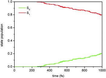 | ||
| Fig. 5 Time-dependent S1 and S0 state populations in the two-state (S1 and S0) photodynamics simulations. | ||
If the S1 excited-state decay is treated as a first-order process, we can estimate the S1 excited-state lifetime τ to be about 3.6 ps according to the single-exponential fitting equation of p = exp(− (t − t0)/τ) + p0, in which the initial delay time t0 and the residual S1 state population p0 are assigned to 258.8 fs and 0.8, respectively.
The distribution of the selected dihedral angles ϕ1 and ϕ2 at all S1 → S0 hopping points in the S1 photodynamics is shown in Fig. 6. The dihedral angles ϕ1(N2C1C3C5) and ϕ2(N2C1C4C6) are mainly distributed around 40–70° and 110–140°, respectively. Such distribution is consistent with the S1 excited-state topological structures computed in the preceding static electronic structure calculations (see above). S1S0-II is energetically the lowest among the three S1/S0 conical intersections: it is about 5.0 kcal mol−1 lower than the other two at the OM2/MRCI and MS-CASPT2 levels (see Table 2). In addition, in our case, along the ϕ1 and ϕ2 dihedral angles, the S1–S0 energy gap is very small; the S1 potential energy surface is very flat and forms an extended conical intersection seam with the S0 state. Therefore, the distribution of these two angles at the hopping points is much spread.
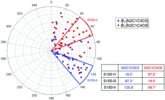 | ||
| Fig. 6 Distribution of the dihedral angles ϕ1(N2C1C3C5) and ϕ2(N2C1C4C6) at the S1 → S0 hopping points. | ||
| Structure | S0 | S1-LE | S1-I1 | S1-I2 |
|---|---|---|---|---|
| OM2/MRCI | 0.0 | 62.5 | 62.2 | 62.2 |
| MS-CASPT2 | 0.0 | 60.0 | 68.1 | 68.1 |
| Structure | S1-II | S1S0-I1 | S1S0-I2 | S1S0-II |
|---|---|---|---|---|
| OM2/MRCI | 60.4 | 66.5 | 67.2 | 62.5 |
| MS-CASPT2 | 64.5 | 74.0 | 74.3 | 69.2 |
It is found from Fig. 7 that 54% hopping-trajectories decay to the S0 state via S1S0-II; and, 11% and 35% hopping-trajectories do via S1S0-I1 and S1S0-I2. How to understand this distribution? First, energetically, S1S0-II is the lowest one among the three S1/S0 conical intersections; the former is computed to be about 5.0 kcal mol−1 lower than the latter two at both OM2/MRCI and MS-CASPT2 levels. Thus, we can understand very well that the preferred S1 → S0 hopping region is close to S1S0-II. Second, why is S1S0-I2 superior to S1S0-I1 for the S1 excited-state deactivation although both conical intersections have nearly same potential energies? It is clear that upon irradiation to the S1 state, the lowest S1 minimum S1-LE is first populated because S1-LE is structurally more close to the Franck–Condon point i.e. the S0 minimum S0 (see Fig. 3). At this point, except proceeding to S1-II, there still exist two other excited-state relaxation paths, first to S1-I1 and second to S1-I2. However, as shown in Fig. 8, the conformational change from S1-LE to S1-I2 is significantly smaller than that from S1-LE to S1-I1. Therefore, more trajectories will decay to the S0 state around S1-I2 via S1S0-I2. In addition, we have computed the averaged S1 → S0 hopping times via S1S0-I1, S1S0-I2, and S1S0-II, which are 441, 597, and 716 fs, respectively, (Table 3).
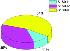 | ||
| Fig. 7 Percentage distribution of the S1 → S0 hoppings via S1S0-I1, S1S0-I2, and S1S0-II conical intersections in the photodynamics of Auramine-O. | ||
 | ||
| Fig. 8 Spatial overlap of the three different S1 geometric structures produced using the VMD1.9.1 package:99 (a) S1-LE and S1-I1 and (b) S1-LE and S1-I2. | ||
| S1S0-I1 | S1S0-I2 | S1S0-II | |
|---|---|---|---|
| t | 441 | 597 | 716 |
Typical trajectories
It is noteworthy that starting from the locally excited S1 minimum S1-LE, there exist three competitive S1 relaxation processes (two sequential and one concerted paths; see panal a of Fig. 9).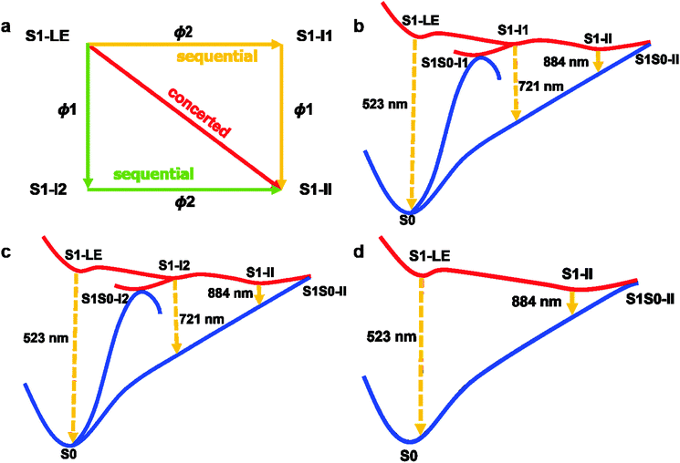 | ||
| Fig. 9 Concerted and sequential deactivation channels proposed based on the present electronic structure calculations and nonadiabatic dynamics simulations. See text for discussion. | ||
The first two relaxation processes are related to the rotation of two dimethylanilino groups (ϕ1 and ϕ2), as shown in panels b and c of Fig. 9. In these two paths, the system near the locally excited S1 minimum first proceeds into a transient excited-state intermediate S1-I1 or S1-I2 via a simple rotation of a dimethylanilino group. These two intermediates S1-I1 and S1-I2 are spectroscopically observed in experiments (see the above discussion). After arriving at S1-I1 or S1-I2, the system not only can decay to the S0 state via the nearby S1/S0 conical intersections S1S0-I1 or S1S0-I2 but also can further evolve into the S1 minimum S1-II by rotating the remaining dimethylanilino group (transient state II in experiments). Finally, the system is de-excited via another S1/S0 conical intersection S1S0-II returning back the S0 state. Certainly, in addition to the sequential paths to S1-II, from the locally S1 excited-state minimum S1-LE the system can also, bypassing S1-I1 and S1-I2, concertedly proceed into the final transient S1 excited-state minimum S1-II.
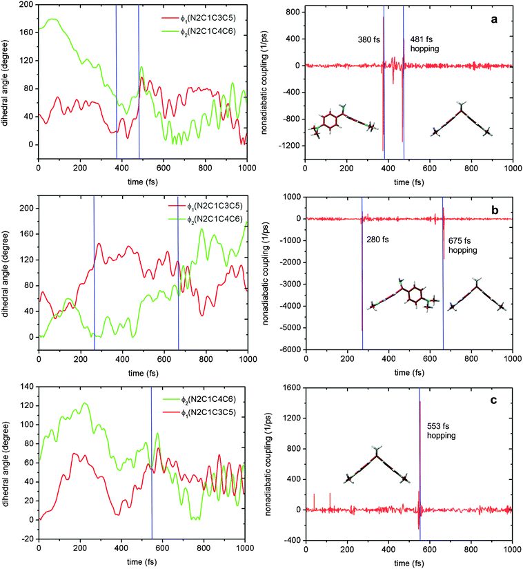
Fig. 10 shows the time-dependent evolution of the two dihedral angles ϕ1 and ϕ2 and the S1–S0 nonadiabatic coupling in three trajectories that support the sketch in Fig. 9. Panels a and b represent the sequential S1 relaxation paths. As shown in panel a, in the first 380 fs, the ϕ2 dihedral angle gradually decreases to about 70° from the initial 160°; while, the corresponding ϕ1 dihedral angle just oscillates around its equilibrium value. At that time, the system still encounters a conical intersection region with large nonadiabatic coupling. However, the system does not hop to the S0 state; instead, it continues to evolve into the S1-II region through rotating the ϕ1 dihedral angle. Near this region, the S1 system jumps to the ground state at 481 fs. The dynamic bahavior of the trajectory in panel b of Fig. 10 is similar to that in panel a, except for rotating the two dihedral angles ϕ1 and ϕ2 in a different order. In contrast, in panel c, the rotations of these two dihedral angles proceed in a synchronous means; hence, the system in this trajectory directly runs into the S1-II region, near which the S0 state is populated at 553 fs as a result of the S1 → S0 internal conversion. Finally, it must be stressed that in our simulations, most of the trajectories decay to the ground state using the concerted way and only a few ones decay to S0via the sequential means.
Correlation with experiments
On the basis of the results of present static electronic structure calculations and dynamics simulations, we have gained several new mechanistic insights into the photophysics of Auramine-O.First, we have for the first time computationally characterized the three S1 excited-state transient states observed in the subpicosecond time-resolved spectroscopic experiments of Singh et al.45 (see above; Fig. 9).
Second, the emission band at ca. 500 nm observed in the steay-state and time-resolved experiments of Erez et al.,49 in terms of our computational results, should be assigned to the locally excited transient state.
Third, in addition to the experimentally proposed sequential S1 relaxation process leading to the transient intermediate S1-II (referred to as TS II in experiments), we have observed a concerted S1 relaxation path to S1-II. This explains why the S1 relaxation process exhibits a multi-exponential excited-state dynamics behavior.45
Fourth, the S1 excited-state decay is experimentally proposed to occur primarily near S1-II.45 However, the corresponding S1/S0 conical intersection is not characterized computationally until now. Here, we not only optimized this conical intersection but also found the other two S1/S0 conical intersections in the vicinity of S1-I1 and S1-I2. The importance of these three conical intersections in the S1 excited-state decay of Auramine-O has been proved in our nonadiabatic dynamics simulations. It is found that S1S0-II plays a major role in the S1 excited-state decay; but, the significance of the other two conical intersections S1S0-I1 and S1S0-I2 cannot be excluded as well, which accounts for 46% of all trajectories that decay to the S0 state.
Fifth, in a recent experimental study, Erez et al. proposed an S1 excited-state deactivation mechanism: the intramolecular rotation of the dimethyl groups around the C–N bond is responsible for the rapid decay (150–300 fs) of the emission band at about 500 nm.49 This mechanism is not supported by our present electronic structure calculations and nonadiabatic dynamics simulations; instead, the S1 excited-state decay should be heavily interrelated with the rotation of the dimethylanilino groups, which is consistent with experiments of Rafiq et al.47 and Singh et al.45
Conclusions
With the use of high-level MS-CASPT2//CASSCF electronic structure calculations and semi-empirical OM2/MRCI nonadiabatic dynamics simulations, we have for the first time theoretically explored the S1 excited-state deactivation mechanism of Auramine-O. First, the S1 excited-state minima, the S1/S0 conical intersections, and the relevant S1 excited-state potential energy profiles are computed at the MS-CASPT2//CASSCF and OM2/MRCI levels. On the basis of these static electronic structure calculations, we have assigned all three transient states proposed in experiments45 and suggested an S1 excited-state decay mechanism involving three S1 transient intermediate states and three S1/S0 conical intersections. Our proposed S1 decay mechanism is immediately verified by our following OM2/MRCI-based surface-hopping dynamics simulations. In addition, we have found that the S1 relaxation process to the final transient state can proceed either sequentially or concertedly. This work represents the first theoretical effort to explore the S1 excited-state deactivation processes of diphenylmethane dyes.Acknowledgements
This work was supported by National Natural Science Foundation of China (21421003); G.C. is also grateful for financial support from “Recruitment Program of Global Youth Experts” and “Fundamental Research Funds for Central Universities”.References
- W. Yu, F. Pellegrino, M. Grant and R. R. Alfano, J. Chem. Phys., 1977, 67, 1766–1773 CrossRef CAS
.
- J. M. Grzybowski, S. E. Sugamori, D. F. Williams and R. W. Yip, Chem. Phys. Lett., 1979, 65, 456–460 CrossRef CAS
.
- D. A. Cremers and M. W. Windsor, Chem. Phys. Lett., 1980, 71, 27–32 CrossRef CAS
.
- R. Menzel, C. W. Hoganson and M. W. Windsor, Chem. Phys. Lett., 1985, 120, 29–34 CrossRef CAS
.
- M. Vogel and W. Rettig, Ber. Bunsen-Ges. Phys. Chem., 1985, 89, 962–968 CrossRef CAS
.
- A. Mokhtari, L. Fini and J. Chesnoy, J. Chem. Phys., 1987, 87, 3429–3435 CrossRef CAS
.
- F. W. Wise, M. J. Rosker and C. L. Tang, J. Chem. Phys., 1987, 86, 2827–2832 CrossRef CAS
.
- M. Canva, G. Le Saux, P. Georges, A. Brun, F. Chaput and J. P. Boilot, Chem. Phys. Lett., 1991, 176, 495–498 CrossRef CAS
.
- M. Ishikawa and Y. Maruyama, Chem. Phys. Lett., 1994, 219, 416–420 CrossRef CAS
.
- K. M. Abedin, J. Y. Ye, H. Inouye, T. Hattori, H. Sumi and H. Nakatsuka, J. Chem. Phys., 1995, 103, 6414–6425 CrossRef CAS
.
- Y. Maruyama, M. Ishikawa and H. Satozono, J. Am. Chem. Soc., 1996, 118, 6257–6263 CrossRef CAS
.
- J. Y. Ye, T. Hattori, H. Inouye, H. Ueta, H. Nakatsuka, Y. Maruyama and M. Ishikawa, Phys. Rev. B: Condens. Matter Mater. Phys., 1996, 53, 8349–8353 CrossRef CAS
.
- J. Y. Ye, T. Hattori, H. Nakatsuka, Y. Maruyama and M. Ishikawa, Phys. Rev. B: Condens. Matter Mater. Phys., 1997, 56, 5286–5296 CrossRef CAS
.
- B. Strehmel, H. Seifert and W. Rettig, J. Phys. Chem. B, 1997, 101, 2232–2243 CrossRef CAS
.
- A. C. Bhasikuttan, L. V. Shastri, A. V. Sapre and J. P. Mittal, J. Photochem. Photobiol., A, 1998, 112, 179–185 CrossRef CAS
.
- J. Y. Ye, M. Ishikawa, O. Yogi, T. Okada and Y. Maruyama, Chem. Phys. Lett., 1998, 288, 885–890 CrossRef CAS
.
- M. Ishikawa, J. Y. Ye, Y. Maruyama and H. Nakatsuka, J. Phys. Chem. A, 1999, 103, 4319–4331 CrossRef CAS
.
- M. Jurczok, P. Plaza, M. M. Martin and W. Rettig, J. Phys. Chem. A, 1999, 103, 3372–3377 CrossRef CAS
.
- Y. Maruyama, O. Magnin, H. Satozono and M. Ishikawa, J. Phys. Chem. A, 1999, 103, 5629–5635 CrossRef CAS
.
- Y. Kanematsu, H. Ozawa, I. Tanaka and S. Kinoshita, J. Lumin., 2000, 87–89, 917–919 CrossRef CAS
.
- M. Glasbeek and H. Zhang, Chem. Rev., 2004, 104, 1929–1954 CrossRef CAS PubMed
.
- M. Kondo, I. A. Heisler, J. Conyard, J. P. H. Rivett and S. R. Meech, J. Phys. Chem. B, 2009, 113, 1632–1639 CrossRef CAS PubMed
.
- M. Kondo, I. A. Heisler and S. R. Meech, Faraday Discuss., 2010, 145, 185–203 RSC
.
- S. Rafiq, B. K. Rajbongshi, N. N. Nair, P. Sen and G. Ramanathan, J. Phys. Chem. A, 2011, 115, 13733–13742 CrossRef CAS PubMed
.
- B. B. Xie, S. H. Xia, L. H. Liu and G. L. Cui, J. Phys. Chem. A, 2015, 119, 5607–5617 CrossRef CAS PubMed
.
- P. Changenet, H. Zhang, M. J. Van Der Meer, M. Glasbeek, P. Plaza and M. M. Martin, J. Phys. Chem. A, 1998, 102, 6716–6721 CrossRef CAS
.
- P. Changenet, H. Zhang, M. J. van der Meer, M. Glasbeek, P. Plaza and M. M. Martin, J. Fluoresc., 2000, 10, 155–160 CrossRef CAS
.
- N. Forsberg and P. A. Malmqvist, Chem. Phys. Lett., 1997, 274, 196–204 CrossRef CAS
.
- M. Hasegawa, T. Sugimura, Y. Suzaki, Y. Shindo and A. Kitahara, J. Phys. Chem., 1994, 98, 2120–2124 CrossRef CAS
.
- N. T. Hunt, A. A. Jaye and S. R. Meech, Chem. Phys. Lett., 2005, 416, 89–93 CrossRef CAS
.
- S. Olsen, J. Phys. Chem. A, 2012, 116, 1486–1492 CrossRef CAS PubMed
.
- P. Prosposito, H. Zhang and M. Glasbeek, J. Sol-Gel Sci. Technol., 2011, 60, 347–351 CrossRef CAS
.
- R. F. Steiner, S. Albaugh, E. Nenortas and L. Norris, Biopolymers, 1992, 32, 73–83 CrossRef CAS PubMed
.
- S. R. Valandro, A. L. Poli, M. G. Neumann and C. C. Schmitt, J. Lumin., 2015, 161, 209–213 CrossRef CAS
.
- Y. Wang and H. Morawetz, Macromolecules, 1986, 19, 1925–1930 CrossRef CAS
.
- J. G. Weers and A. H. Maki, Biochemistry, 1986, 25, 2897–2904 CrossRef CAS PubMed
.
- G. Oster and Y. Nishijima, J. Am. Chem. Soc., 1956, 78, 1581–1584 CrossRef CAS
.
- T. Förster and G. Hoffmann, Z. Phys. Chem., Neue Folge, 1971, 75, 63–76 CrossRef
.
- B. Bagchi, G. R. Fleming and D. W. Oxtoby, J. Chem. Phys., 1983, 78, 7375–7385 CrossRef CAS
.
- M. Glasbeek, H. Zhang and M. J. Van der Meer, J. Mol. Liq., 2000, 86, 123–126 CrossRef CAS
.
- M. J. Van Der Meer, H. Zhang and M. Glasbeek, J. Chem. Phys., 2000, 112, 2878–2887 CrossRef CAS
.
- Y. Hirose, H. Yui and T. Sawada, J. Phys. Chem. B, 2004, 108, 9070–9076 CrossRef CAS
.
- I. A. Heisler, M. Kondo and S. R. Meech, J. Phys. Chem. B, 2009, 113, 1623–1631 CrossRef CAS PubMed
.
- M. Kondo, I. A. Heisler and S. R. Meech, J. Mol. Liq., 2012, 176, 17–21 CrossRef CAS
.
- C. Singh, B. Modak, J. A. Mondal and D. K. Palit, J. Phys. Chem. A, 2011, 115, 8183–8196 CrossRef CAS PubMed
.
- P. K. Singh, A. K. Mora, S. Murudkar and S. Nath, RSC Adv., 2014, 4, 34992–35002 RSC
.
- S. Rafiq and P. Sen, J. Chem. Phys., 2013, 139, 124302 CrossRef PubMed
.
- Y. Erez, N. Amdursky, R. Gepshtein and D. Huppert, J. Phys. Chem. A, 2012, 116, 12056–12064 CrossRef CAS PubMed
.
- Y. Erez, R. Simkovitch, K. Akulov, R. Gepshtein, T. Schwartz and D. Huppert, J. Phys. Chem. C, 2014, 118, 27063–27073 CAS
.
-
R. G. Parr and W. T. Yang, Density-Functional Theory of Atoms and Molecules, Oxford University Press, USA, 1994 Search PubMed
.
- S. H. Vosko, L. Wilk and M. Nusair, Can. J. Phys., 1980, 58, 1200–1211 CrossRef CAS
.
- C. Lee, W. T. Yang and R. G. Parr, Phys. Rev. B: Condens. Matter Mater. Phys., 1988, 37, 785–789 CrossRef CAS
.
- A. D. Becke, Phys. Rev. A: At., Mol., Opt. Phys., 1988, 38, 3098–3100 CrossRef CAS
.
- A. D. Becke, J. Chem. Phys., 1993, 98, 1372–1377 CrossRef CAS
.
- K. Andersson, P. A. Malmqvist, B. O. Roos, A. J. Sadlej and K. Wolinski, J. Phys. Chem., 1990, 94, 5483–5488 CrossRef CAS
.
- K. Andersson, P. Å. Malmqvist and B. O. Roos, J. Chem. Phys., 1992, 96, 1218–1226 CrossRef CAS
.
- F. Aquilante, R. Lindh and T. Bondo Pedersen, J. Chem. Phys., 2007, 127, 114107 CrossRef PubMed
.
- G. Ghigo, B. O. Roos and P. Malmqvist, Chem. Phys. Lett., 2004, 396, 142–149 CrossRef CAS
.
- N. Försberg and P. Å. Malmqvist, Chem. Phys. Lett., 1997, 274, 196–204 CrossRef
.
-
M. A. L. Marques, C. A. Ullrich, F. Nogueira, A. Rubio, K. Burke and E. K. U. Gross, Time-dependent Density Functional, Springer, 2006 Search PubMed
.
- T. Yanai, D. P. Tew and N. C. Handy, Chem. Phys. Lett., 2004, 393, 51–57 CrossRef CAS
.
- R. Ditchfield, W. J. Hehre and J. A. Pople, J. Chem. Phys., 1971, 54, 724–728 CrossRef CAS
.
- M. M. Francl, W. J. Pietro, W. J. Hehre, J. S. Binkley, M. S. Gordon, D. J. DeFrees and J. A. Pople, J. Chem. Phys., 1982, 77, 3654–3665 CrossRef CAS
.
- G. L. Cui, P. J. Guan and W.-H. Fang, J. Phys. Chem. A, 2014, 118, 4732–4739 CrossRef CAS PubMed
.
- P. J. Guan, G. L. Cui and Q. Fang, ChemPhysChem, 2015, 16, 805–811 CrossRef CAS PubMed
.
-
M. J. Frisch, G. W. Trucks, H. B. Schlegel, G. E. Scuseria, M. A. Robb, J. R. Cheesem, G. Scalmani, V. Barone, B. Mennucci, G. A. Petersson, H. Nakatsuji, M. Caricato, X. Li, H. P. Hratchian, A. F. Izmaylov, J. Bloino, G. Zheng, J. L. Sonnenberg, M. Hada, M. Ehara, K. Toyota, R. Fukuda, J. Hasegawa, M. Ishida, T. Nakajima, Y. Honda, O. Kitao, H. Nakai, T. Vreven, J. A. Montgomery, Jr., J. E. Peralta, F. Ogliaro, M. Bearpark, J. J. Heyd, E. Brothers, K. N. Kudin, V. N. Staroverov, R. Kobayashi, J. Normand, K. Raghavachari, A. Rendell, J. C. Burant, S. S. Iyengar, J. Tomasi, M. Cossi, N. Rega, J. M. Millam, M. Klene, J. E. Knox, J. B. Cross, V. Bakken, C. Adamo, J. Jaramillo, R. Gomperts, R. E. Stratmann, O. Yazyev, A. J. Austin, R. Cammi, C. Pomelli, J. W. Ochterski, R. L. Martin, K. Morokuma, V. G. Zakrzewski, G. A. Voth, P. Salvador, J. J. Dannenberg, S. Dapprich, A. D. Daniels, O. Farkas, J. B. Foresman, J. V. Ortiz, J. Cioslowski and D. J. Fox, Gaussian 09, Revision A.02, Gaussian, Inc., Wallingford CT, 2009 Search PubMed
.
-
H.-J. Werner, P. J. Knowles, G. Knizia, F. R. Manby, M. Schütz, P. Celani, T. Korona, R. Lindh, A. Mitrushenkov, G. Rauhut, K. R. Shamasundar, T. B. Adler, R. D. Amos, A. Bernhardsson, A. Berning, D. L. Cooper, M. J. O. Deegan, A. J. Dobbyn, F. Eckert, E. Goll, C. Hampel, A. Hesselmann, G. Hetzer, T. Hrenar, G. Jansen, C. Köppl, Y. Liu, A. W. Lloyd, R. A. Mata, A. J. May, S. J. McNicholas, W. Meyer, M. E. Mura, A. Nicklass, D. P. O'Neill, P. Palmieri, D. Peng, K. Pflüger, R. Pitzer, M. Reiher, T. Shiozaki, H. Stoll, A. J. Stone, R. Tarroni, T. Thorsteinsson and M. Wang, MOLPRO, version 2012.1, a package of ab initio programs, 2012, see http://www.molpro.net Search PubMed
.
- G. Karlström, R. Lindh, P. Å. Malmqvist, B. O. Roos, U. Ryde, V. Veryazov, P. O. Widmark, M. Cossi, B. Schimmelpfennig, P. Neogrady and L. Seijo, Comput. Mater. Sci., 2003, 28, 222–229 CrossRef
.
- F. Aquilante, L. De Vico, N. Ferré, G. Ghigo, P. Malmqvist, P. Neogrády, T. B. Pedersen, M. Pitoňák, M. Reiher, B. O. Roos, L. Serrano-Andrés, M. Urban, V. Veryazov and R. Lindh, J. Comput. Chem., 2010, 31, 224–247 CrossRef CAS PubMed
.
-
W. Weber, PhD thesis, University of Zürich, 1996
.
- W. Weber and W. Thiel, Theor. Chem. Acc., 2000, 103, 495–506 CrossRef CAS
.
- A. Koslowski, M. E. Beck and W. Thiel, J. Comput. Chem., 2003, 24, 714–726 CrossRef CAS PubMed
.
-
W. Thiel, MNDO99 program, version 6.1, Max-Planck-Institut für Kohlenforschung, Mülheim, Germany, 2007 Search PubMed
.
- D. R. Yarkony, J. Chem. Phys., 2001, 114, 2601–2613 CrossRef CAS
.
- T. W. Keal, A. Koslowski and W. Thiel, Theor. Chem. Acc., 2007, 118, 837–844 CrossRef CAS
.
- G. Granucci, M. Persico and A. Zoccante, J. Chem. Phys., 2010, 133, 134111 CrossRef PubMed
.
- M. R. Silva-Junior and W. Thiel, J. Chem. Theory Comput., 2010, 6, 1546–1564 CrossRef CAS
.
- M. Barbatti, A. J. A. Aquino, J. J. Szymczak, D. Nachtigallova, P. Hobza and H. Lischka, Proc. Natl. Acad. Sci. U. S. A., 2010, 107, 21453–21458 CrossRef CAS PubMed
.
- D. Nachtigallova, T. Zeleny, M. Ruckenbauer, T. Müller, M. Barbatti, P. Hobza and H. Lischka, J. Am. Chem. Soc., 2010, 132, 8261–8263 CrossRef CAS PubMed
.
- T. Zelený, M. Ruckenbauer, A. J. A. Aquino, T. Müller, F. Lankaš, T. Dršata, W. L. Hase, D. Nachtigallova and H. Lischka, J. Am. Chem. Soc., 2012, 134, 13662–13669 CrossRef PubMed
.
- H. L. Tao, B. G. Levine and T. J. Martinez, J. Phys. Chem. A, 2009, 113, 13656–13662 CrossRef CAS PubMed
.
- M. Richter, P. Marquetand, J. González-Vázquez, I. Sola and L. González, J. Phys. Chem. Lett., 2012, 3, 3090–3095 CrossRef CAS PubMed
.
- L. Martnez-Fernández, I. Corral, G. Granucci and M. Persico, Chem. Sci., 2014, 5, 1336–1347 RSC
.
- G. L. Cui and W. Thiel, J. Chem. Phys., 2014, 141, 124101 CrossRef PubMed
.
- G. L. Cui and W. Thiel, Angew. Chem., Int. Ed., 2013, 52, 433–436 CrossRef CAS PubMed
.
- G. L. Cui, Z. G. Lan and W. Thiel, J. Am. Chem. Soc., 2012, 134, 1662–1672 CrossRef CAS PubMed
.
- G. L. Cui and W. Thiel, Phys. Chem. Chem. Phys., 2012, 14, 12378–12384 RSC
.
- L. Spörkel, G. L. Cui, A. Koslowski and W. Thiel, J. Phys. Chem. A, 2013, 118, 152–157 CrossRef PubMed
.
- L. Spörkel, G. L. Cui and W. Thiel, J. Phys. Chem. A, 2013, 117, 4574–4583 CrossRef PubMed
.
- O. Weingart, Z. G. Lan, A. Koslowski and W. Thiel, J. Phys. Chem. Lett., 2011, 2, 1506–1509 CrossRef CAS
.
- A. Kazaryan, Z. G. Lan, L. V. Schafer, W. Thiel and M. Filatov, J. Chem. Theory Comput., 2011, 7, 2189–2199 CrossRef CAS PubMed
.
- Y. Lu, Z. G. Lan and W. Thiel, Angew. Chem., Int. Ed., 2011, 50, 6864–6867 CrossRef CAS PubMed
.
- E. Fabiano, T. W. Keal and W. Thiel, Chem. Phys., 2008, 349, 334–347 CrossRef CAS
.
- J. B. Schönborn, A. Koslowski, W. Thiel and B. Hartke, Phys. Chem. Chem. Phys., 2012, 14, 12193–12201 RSC
.
- J. B. Schönborn and B. Hartke, Phys. Chem. Chem. Phys., 2014, 16, 2483–2490 RSC
.
- R. B. Gerber, D. Shemesh, M. E. Varner, J. Kalinowski and B. Hirshberg, Phys. Chem. Chem. Phys., 2014, 16, 9760–9775 RSC
.
- D. Shemesh, S. L. Blair, S. A. Nizkorodov and R. B. Gerber, Phys. Chem. Chem. Phys., 2014, 16, 23861–23868 RSC
.
- S.-H. Xia, B.-B. Xie, Q. Fang, G. Cui and W. Thiel, Phys. Chem. Chem. Phys., 2015, 17, 9687–9697 RSC
.
- W. Humphrey, A. Dalke and K. Schulten, J. Mol. Graphics, 1996, 14, 33–38 CrossRef CAS PubMed
.
Footnote |
| † Electronic supplementary information (ESI) available: Active orbitals in the OM2/MRCI and CASSCF computations and Cartesian coordinates of all optimized structures and paths. See DOI: 10.1039/c5cp05312a |
| This journal is © the Owner Societies 2016 |

