
Photobleaching and stabilization of carbon nanodots produced by solvothermal synthesis†
Wenshuo
Wang
,
Cornelia
Damm
,
Johannes
Walter
,
Thomas J.
Nacken
and
Wolfgang
Peukert
*
Friedrich-Alexander University Erlangen-Nürnberg, Institute of Particle Technology, Cauerstrasse 4, 91058 Erlangen, Germany. E-mail: wolfgang.peukert@fau.de; Fax: +49 9131 85 29402; Tel: +49 9131 85 29400
First published on 17th November 2015
Abstract
In this work we performed a detailed investigation of the photostability of bottom-up produced carbon nanodots (CDs) prepared from citric acid and urea by solvothermal synthesis. Analytical ultracentrifugation (AUC) reveals that the CDs have a hydrodynamic diameter of <1 nm and a very narrow size distribution. In the community it is widely assumed that CDs are photo-stable. In contrast, we found that CDs exposed to UV-irradiation exhibit noteworthy fluorescence degeneration compared to freshly prepared CDs or CDs stored in the dark, indicating that fluorescence bleaching is caused by a photochemical process. We found that fluorescence intensity decay due to exposure to UV-irradiation is accelerated in the presence of oxygen and identified the surface status of CDs as the decisive factor of fluorescence bleaching of CDs. Based on a discussion on the underlying mechanisms we show how to avoid photobleaching of CDs.
Introduction
Carbon allotropes which include diamond, graphite, graphene, carbon nanotubes and fullerenes are already well-known. As a rising star of the carbon family, carbon nanodots (CDs) have recently received enormous attention because of their unique chemical, electronic and optical properties. CDs are a new class of carbon nanomaterials with exceptional photoluminescence properties. Depending on the production conditions (top-down or bottom-up) CDs can be crystalline or amorphous.1,2 The formation mechanism of CDs, their structure and the origin of their fluorescence, however, are not well understood. However, due to their great application potential accompanied by aforementioned unsolved questions, CDs are currently being investigated by many groups.3–5In previous studies, CDs were assumed to be highly photo-stable showing an outstanding resistance to photobleaching. The photostability of CDs is a necessary precondition for related applications in bioimaging,6,7 photosensing8–10 and energy related applications.11–13 Studies on the photostability of CDs itself, however, are very limited. Zhao et al. demonstrated that the CDs produced by electro-oxidation of graphite showed no appreciable changes in photoluminescence intensity even after continuous exposure to white light of a 8.3 W Xe lamp.14 Zhang et al. prepared graphitic-C3N4 dots for the first time and showed that these dots exhibit negligible photobleaching even after UV illumination for 12 hours.15 Accordingly, Peng et al. showed that the CDs synthesized by carbohydrate dehydration exhibit considerable photostability, i.e. the emission intensity decreases by only 17% after 19 h of continuous excitation at 360 nm.16 All these studies were performed for crystalline CDs. Zhu and his co-workers found that the photoluminescence intensity of hydrothermally synthesized CDs decreased dramatically only after 9 minutes of illumination with 2000 W ultraviolet (UV) exposure.17 The differences in the photostability of CDs come obviously from varying structures due to different synthetic routes.
The term CDs includes carbon dots synthesized using top-down and bottom-up methods, i.e. graphene quantum dots, carbon based polymer dots and so on. Some of these have layered structures similar to graphite, but often amorphous CDs are obtained. Most of the tiny CDs with particle size usually smaller than 20 nm exhibit remarkable blue or green fluorescence under UV excitation, low cell toxicity and consist of sp2/sp3 carbon and oxygen/nitrogen containing functional groups on the surface. Gradually, it becomes clear that the synthetic route plays a decisive role in the particular structure and photoluminescence properties of CDs. The CDs synthesized from “bottom-up” are always quasi-spherical without a crystal lattice. These CDs consist of aggregated or cross-linked structures from monomers or linear polymers formed using solvothermal,15–22 microwave,11,23,24 or calcination25 methods. Their spectral feature of fluorescence is usually independent of excitation wavelength with a high quantum yield of up to ∼70%.26 In contrast, the CDs synthesized using “top-down” methods always have a sheet-like structure and are crystalline. These kinds of CDs can be called graphene-like quantum dots. They are produced by size reduction from various carbon sources.27,28 Their fluorescence spectrum is usually dependent on excitation wavelength with a relatively low quantum yield of lower than 15%.29–31 The carbon dots formed through bottom-up approaches are more well known because of their facile synthesis and outstanding fluorescence quantum yield. So far, their photo-stability has not been studied in detail, but is a crucial factor for any application. Thus, in this work, we systematically investigate the fluorescence photobleaching of bottom-up prepared CDs and show how photobleaching can be avoided.
Experimental
CD synthesis
In a typical synthesis, 18.9 g of citric acid and 16.2 g of urea (both were obtained from Carl Roth, Germany) were dissolved in 150 mL of deionized water. Then the solution was transferred to a poly(tetrafluoroethylene) (Teflon)-lined autoclave (250 mL) and heated at 200 °C for 8 h. After the hydrothermal reaction, the reactor was cooled to room temperature. The product was filtered through a membrane with 0.22 μm pores to remove bulk impurities and then subjected to dialysis (molecular weight cut off of the membrane: 1000 g mol−1, obtained from Spectrum Laboratories Inc., America) to remove unreacted citric acid and urea. The obtained aqueous CD suspension appeared to be brownish and transparent. The production yield was about 60%.Characterization and devices
UV-Vis absorption spectra were recorded in the range from 200 to 800 nm using a Cary 100 (Varian) spectrometer. Fluorescence spectra were recorded using a Jobin-Yvon photoluminescence spectrometer (Horiba, Japan). All absorbance and fluorescence spectra were recorded at room temperature using quartz cuvettes with a path length of 10 mm. Up-conversion fluorescence was recorded at various incident angles to discharge the illusion caused by second-order diffraction light from the monochromators in the spectrometer. Fluorescence quantum yields (QY) were determined using the slope method described in ref. 32–34 using quinine sulfate as standard (Sigma-Aldrich, America, QY: 54.6%). The value of the quantum yield of sample QYx is calculated using eqn (1):| QYx = QYstd(φx/φstd)(nx/nstd)2 | (1) |
Raman spectra were recorded in the wavenumber range from 500 to 3750 cm−1 using a confocal Raman microscope “LabRAM HR Evolution” (Horiba Jobin-Yvon, Germany) equipped with a Nd3+YAG laser (532 nm). A 100× objective was used (beam diameter ∼0.7–0.8 μm). Prior to Raman measurements the CDs were deposited on SiO2 wafers with a 300 nm thick silica shell on top by drop coating. Fourier transform infrared (FTIR) spectra were recorded using a “Digilab FTS3100” FTIR spectrometer. The samples were compressed with KBr to disks. The height of the as-prepared CDs was measured using a “NanoWizard 3” (JPK Instruments, Germany) atomic force microscope (AFM) in the tapping mode using NSC15/AlBS cantilevers (frequency 325 kHz, spring constant 46 N m−1 and nominal tip radius <10 nm). CDs were deposited on a mica sheet for AFM-measurement. The zeta-potential was measured via the electrophoretic mobility of CDs using a “Zetaszier Nano-ZS” (Malvern Instruments, UK).
For the investigation of the photostability of CDs, UV illumination was carried out using a UV-8 SL ultraviolet lamp (Konrad Benda, Germany). The UV lamp was situated in a dark box to prevent any UV leakage. CD samples were placed in the dark box for UV illumination for times between 1 and up to 48 h. The power output of the UV lamp was 8 W and the incident intensity was 950 μW cm−2.
A preparative centrifuge “Optima L-90K” (Beckman Coulter, USA) modified with a multi wavelength (MWL)-detector was used to perform sedimentation velocity experiments (SV-AUC). More information regarding the hardware and data acquisition can be found in the literature.35 Two-sector titanium centrepieces from Nanolytics, Germany, with a path length of 12 mm were used. Water with 50 mM NaCl was used as a solvent. The partial specific volume ![[v with combining macron]](https://www.rsc.org/images/entities/i_char_0076_0304.gif) of the freshly prepared CDs was measured using a “DMA 5000M” density meter (Anton Paar, Austria) and Kratky's density balance.36 A of 0.5278 cm3 g−1 was found for the as-prepared CDs. For the UV-treated particles could not be measured because the concentration was too low to provide reliable results. Instead, the same as for the as-prepared CDs was used for further analysis. SV data was acquired every two to ten minutes at 55
of the freshly prepared CDs was measured using a “DMA 5000M” density meter (Anton Paar, Austria) and Kratky's density balance.36 A of 0.5278 cm3 g−1 was found for the as-prepared CDs. For the UV-treated particles could not be measured because the concentration was too low to provide reliable results. Instead, the same as for the as-prepared CDs was used for further analysis. SV data was acquired every two to ten minutes at 55![[thin space (1/6-em)]](https://www.rsc.org/images/entities/char_2009.gif) 000 rpm for 30 h, 25 °C and a radial resolution of 50 μm. Multi-wavelength intensity data were recorded and converted to absorbance data. Data at a wavelength of 300 nm was used for data evaluation using the software UltraScan3 (Version 3.3, Revision 1977) including 2-dimensional spectrum analysis (2DSA) and Monte Carlo (MC) analysis.37 During 200 MC iterations synthetic noise is generated and applied to the best fit to calculate the statistic parameters for the sedimentation coefficient s and the diffusion coefficient D. Details regarding the 2DSA-MC can be found in ref. 38. CDs were measured twice and the mean values were used for evaluation.
000 rpm for 30 h, 25 °C and a radial resolution of 50 μm. Multi-wavelength intensity data were recorded and converted to absorbance data. Data at a wavelength of 300 nm was used for data evaluation using the software UltraScan3 (Version 3.3, Revision 1977) including 2-dimensional spectrum analysis (2DSA) and Monte Carlo (MC) analysis.37 During 200 MC iterations synthetic noise is generated and applied to the best fit to calculate the statistic parameters for the sedimentation coefficient s and the diffusion coefficient D. Details regarding the 2DSA-MC can be found in ref. 38. CDs were measured twice and the mean values were used for evaluation.
Results and discussion
Morphology of the CDs
The morphology of CDs is investigated using AFM and AUC. The results by AFM indicate that the CDs (Fig. 1) are evenly distributed on the substrate. The heights of the CDs are in the range of 1–3 nm. 200 objects were statistically evaluated and the average height of CDs was 2.7 nm corresponding to the typical value reported for CDs prepared using microwave,11,39 electrochemical40 and pyrolysis41 approaches. Some larger particles with heights above 5 nm were also detected, see Fig. 1c.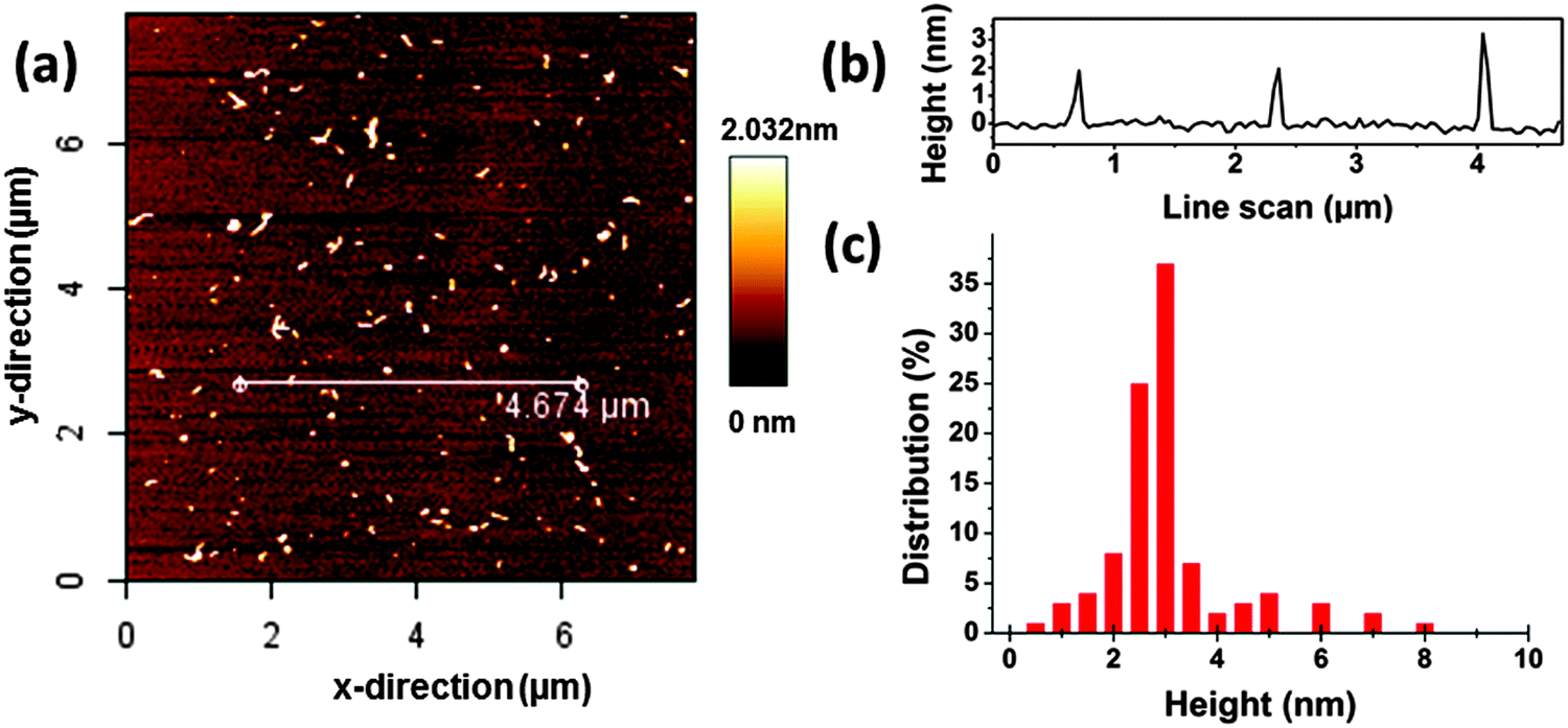 | ||
| Fig. 1 (a) AFM image of carbon dots (CDs) on a mica substrate, 8 × 8 μm. (b) Measured height profile along the white line in (a). (c) Height distribution from the analysis of the AFM images. | ||
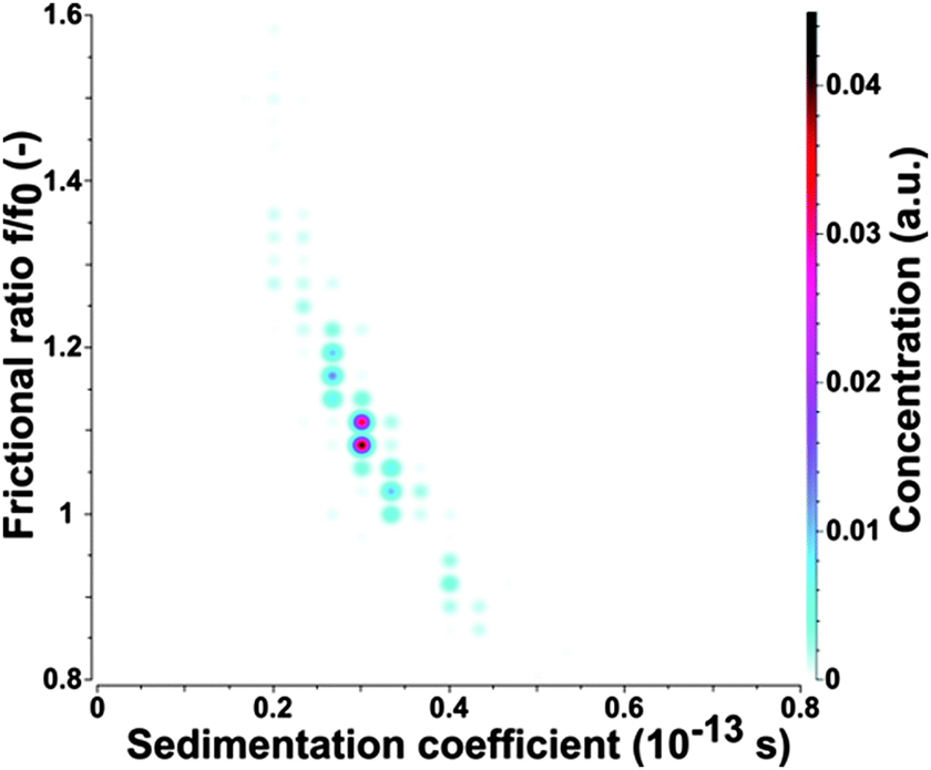
To confirm the AFM results the as-prepared CDs were subjected to analytical ultracentrifugation (AUC) experiments. A recent study demonstrated that AUC is able to analyze the hydrodynamic properties of CDs directly in solution.23 SV-AUC was performed to obtain the sedimentation (s) and diffusion (D) coefficients, which are linked to the size and shape of the CDs. The AUC analyses provided narrow distributions for s and D. An exemplary pseudo 3-dimensional plot for a freshly prepared CD sample is shown in Fig. 2. The mean s of a freshly prepared CD sample was 0.352 ± 0.012 sved and D was (4.650 ± 0.026) × 10−6 cm2 s−1. The frictional ratio f/f0 as a measure of the shape anisotropy was found to be 1.067 ± 0.016. This value is very close to 1 and confirms the nearly spherical shape of the CDs. The mean hydrodynamic diameter of the CDs was found to be 0.921 ± 0.005 nm based on the Stokes–Einstein relation.
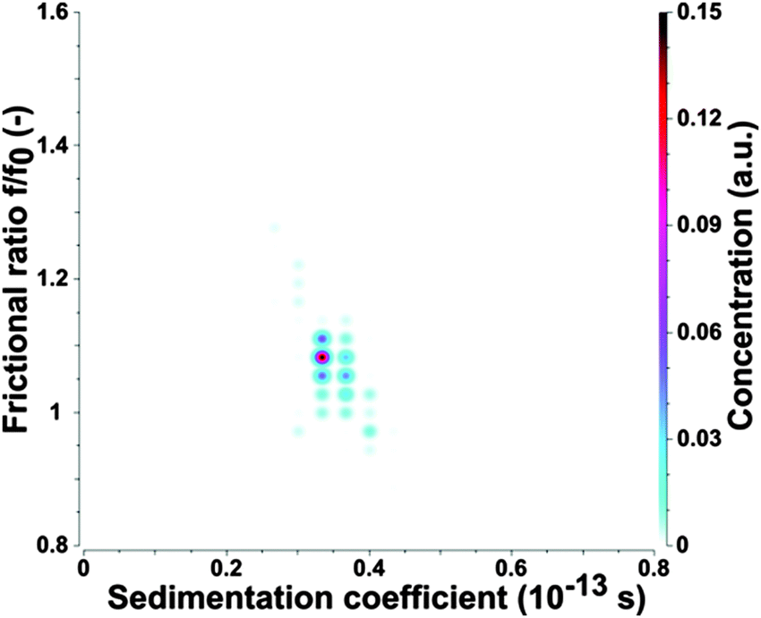 | ||
| Fig. 2 Pseudo-3D plot of the CDs as found by 2DSA-MC. A narrow distribution in s and D is found for the as prepared sample. The sedimentation coefficient is shown for water under standard conditions (20 °C). | ||
The hydrodynamic diameter of the CDs measured by AUC is by a factor of about 2–3 lower in comparison to the mean diameter derived from AFM height profile measurements, see Fig. 1 and 2. This indicates that particle sizes of ∼5 nm and higher are probably formed by agglomeration processes occurring during sample preparation for AFM. The AUC measurements should reflect the true diameter of the CDs in solution.
Optical properties of the CDs
In the UV-Vis spectra (see the ESI,† Fig. S1), the absorbance peak of an aqueous solution of CDs is focused around 346 nm and is associated with an n–π* transition. In contrast to the UV absorption spectra of CDs, citric acid and urea do not show any absorbance peak at around 350 nm. Thus, this peak indicates additional chromophores in the CD structure, which are not present in citric acid and urea. The CD suspensions exhibit also a weak absorption peak at ∼600–700 nm in the visible region, which may be attributed to the amino-functionalized surface of the CDs. We can exclude aggregation of the CDs as the origin of absorbance at around 600–700 nm because AUC gives no evidence of any aggregation. This technique may even detect the formation of dimers (as shown for proteins, for instance). Moreover, the CDs own an intense surface potential preventing aggregation by electrostatic repulsion. In the fluorescence spectra, CDs have optimal excitation and emission wavelengths at ∼370 nm and ∼440 nm, respectively. The shape of the fluorescence spectrum of the CDs is independent of the excitation wavelength, see Fig. 3. For excitation wavelengths between 290 nm and 400 nm the emission peaks are fixed at 440 nm, see Fig. 3. The 3D-luminescence plots of CDs synthesized at different temperatures are shown in Fig. S2 in the ESI.† For all investigated synthesis temperatures, the CDs manifest excitation-independent fluorescence spectra. Besides the normal fluorescence of CDs also the up-conversion fluorescence spectrum excited by NIR or by long-wavelength visible light (600–700 nm) is independent of the excitation wavelength and the emission maximum is fixed also at 440 nm. The excitation-independent emission feature of CDs implies that both the size and the surface state of CDs should be uniform.19 The CDs show well-defined absorption and PL bands at 346 and 440 nm with a narrow FWHM of 45 and 65 nm, respectively, which further confirms that the CDs should be uniform in their surface states. The uniform size and structure of the CDs derived from their optical properties are in agreement with the narrow size distribution found by AUC, see Fig. 1 and 2.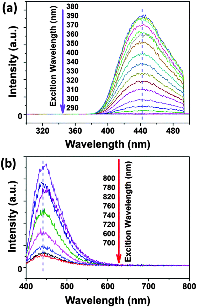 | ||
| Fig. 3 The excitation-wavelength independent fluorescence spectra of CDs in (a) normal fluorescence and (b) up-conversion fluorescence. | ||
Similar to most fluorescent substances, CDs exhibit obvious self-quenching (concentration-quenching) effects.31 As the concentration increases, the fluorescence intensity decreases. As shown in Fig. 4, the CDs at an appropriate low concentration (∼0.025 wt%) exhibit the strongest fluorescence intensity, while high concentrations lead to drastic quenching and the emission wavelength is red shifted.
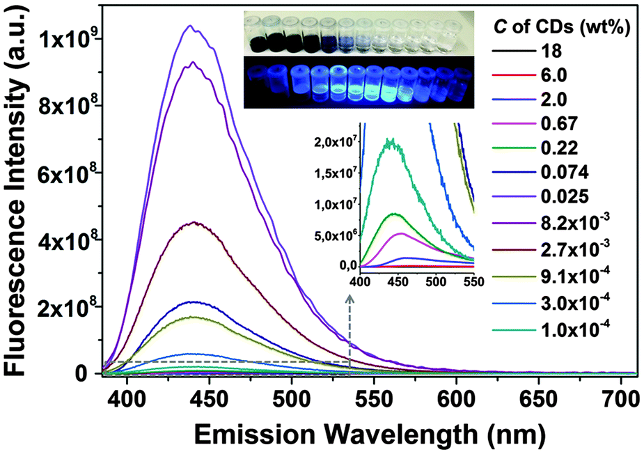 | ||
| Fig. 4 Self-quenching of CD fluorescence. The insets show the photos of different concentrated CD suspensions under sun light (above) and UV light (below). | ||
The fluorescence intensity normalized to the concentration of CDs is shown in Fig. 5a, which represents the trend of relative quantum yield. Light screening of highly concentrated samples (above 0.1 wt%) may be a reason for the low quantum yield because the re-absorption of emitted light by CD suspensions increases with concentration according to the Lambert–Beer law, see Fig. S3 in the ESI.† However, even if reabsorption is considered, a noteworthy decrease in the relative quantum yield with increasing CD concentration is observed. Transmittance significantly decreases at concentrations higher than 0.67 wt%, while at the concentration of 0.0082 wt%, the relative quantum yield already decreases, see Fig. 5a. Thus, the lower quantum yield at a higher concentration of CDs is attributed to the energy transfer. CDs are considered to consist of a carbon core and effective fluorophores at their surface, as schematically depicted in Fig. 5b. Once the fluorophores come too close to each other, transient excited-state interactions may lead to fluorescence quenching or the formation of non-fluorescent ground-state species may be anticipated. Upon dilution of the CD suspension, the short-range interaction gradually disappears. For concentrations lower than 0.0082 wt%, the as-prepared CDs emitted strong blue fluorescence under excitation with 365 nm UV light with a high quantum yield of 34.8% (Fig. S4, ESI†).
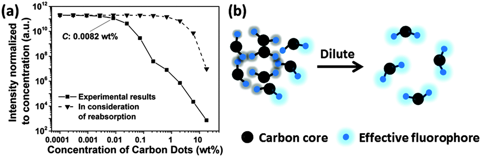 | ||
| Fig. 5 (a) Fluorescence intensity normalized to the concentration of CDs as a function of concentration. The dependence indicates that for CD concentrations above 0.0082 wt% the fluorescence quantum yield of CDs decreases with increasing CD concentration. (b) The schematic diagram depicts the self-quenching of CD fluorescence. | ||
Photobleaching of the CDs
In aqueous solution, the CDs showed significant photobleaching of their fluorescence. The 3D-luminescence plots of CDs in Fig. 6a–c exhibit obviously weakened fluorescence after mild UV exposure (950 μW cm−2) for 0–17 h illumination. The emission center wavelength and FWHM of the emission peak remained unchanged, whereas the fluorescence intensity dropped to less than 10% after 17 h of exposure compared to the original intensity, see Fig. 6d. Photobleaching was also found in up-conversion fluorescence of CDs, see Fig. 6e. Other factors influencing the fluorescence intensity of CDs are pH and ionic strength of the solvent leading to changes in the surface status of the CDs.18,42–44 It is also expected that fluorescence photobleaching is a consequence of changes in the structure of functional groups at the surface. In contrast to fluorescence intensity changes due to variations in pH or ionic strength, fluorescence degeneration by photobleaching is irreversible. It should be noted, though, that photobleaching does not lead to a complete loss of fluorescence. As shown in Fig. S4 (ESI†), for very long UV exposure, the quantum yield of CDs declined slowly and remained constant at about 3%. This observation could be a general trend for bottom-up synthesized CDs, since CDs prepared using the microwave method (synthesized for 10 minutes at 110 °C) also exhibited a very similar fluorescence photobleaching behavior as the hydrothermally synthesized CDs. Thus, we use the hydrothermally synthesized CDs here as a representative sample.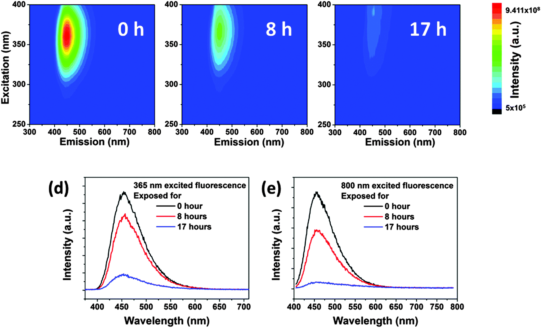 | ||
| Fig. 6 3D-luminescence plots of CDs after (a) 0, (b) 8 and (c) 17 hours of UV-exposure in aqueous solution at room temperature. Intensity increases from blue to green and to red. The luminescence spectra of CDs in aqueous solutions upon (d) 365 and (e) 800 nm excitation at room temperature, respectively. | ||
The extent of fluorescence photobleaching is mainly dependent on the duration and intensity of exposure to light, but it also depends on the concentration of CDs. The lower the concentration the easier the fluorescence bleaching of CDs as shown in Fig. 7a. If a concentrated CD suspension (2 wt% in Fig. 7b) is exposed to UV light for 17 h and subsequently diluted to a low concentration (0.025 wt%), fluorescence intensity is regained. The fluorescence intensity after dilution was close to the value of the original CD sample at low concentration. Thus, we infer that well dispersed CDs are easier to be bleached than dense CD dispersions (Fig. 7c and d). The first explanation is that light screening works effectively at higher concentrations. Hence, most photons are absorbed by outer CDs, while few photons can reach the CDs inside of the sample. The second reason is energy dissipation on different CDs at high concentration leading to further dampening of the bleaching effect. As the concentration is lower than 0.1 wt%, light can pass through the sample and reach all CDs.
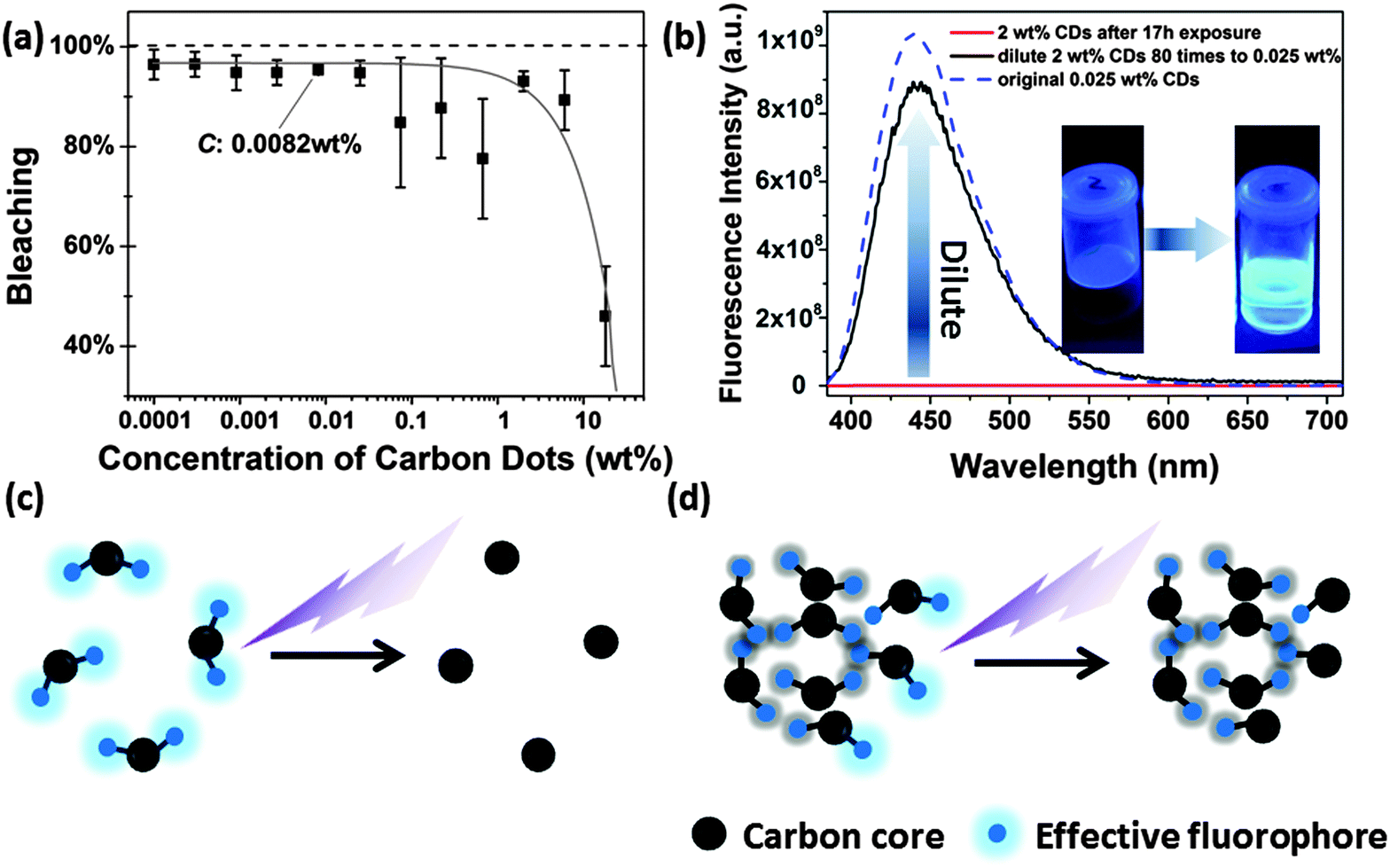 | ||
| Fig. 7 (a) Percentage of fluorescence bleaching as a function of CD concentration. (b) After dilution, the fluorescence intensity of the exposed concentrated CD suspension is almost recovered to the value of the as-prepared diluted sample. (c) Schematic diagram to explain fluorescence photobleaching of low concentrated CD suspensions. (d) Schematic diagram to explain photobleaching of highly concentrated CD suspensions. | ||
Furthermore, a photo-oxidation process could play a major role in the photo-induced fluorescence bleaching of the CDs. Therefore, the influence of oxygen on fluorescence bleaching was investigated. For this study, suspensions of 0.002 wt% CDs in water were used, because the photobleaching phenomenon is most pronounced at low CD concentrations, see Fig. 7. If dissolved oxygen is removed by purging the CD suspension with nitrogen before and during UV exposure fluorescence photobleaching still occurs, but the rate of fluorescence decay with illumination time becomes lower, see Fig. 8. Ascorbic acid which acts as a reducing agent and as a radical scavenger is also able to slow down the fluorescence bleaching rate of CDs in air-saturated water, see Fig. 8.
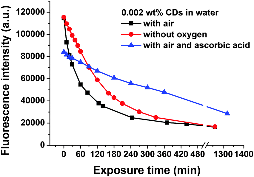 | ||
| Fig. 8 Kinetics of UV-induced fluorescence photobleaching of a suspension of 0.002 wt% CDs in water in the absence and in the presence of oxygen and in the presence of ascorbic acid. | ||
The results in Fig. 8 indicate that photo-oxidation processes as well as free radicals which are also formed under anaerobic conditions must contribute to the fluorescence bleaching of CDs. It is expected that in water mainly OH-radicals are formed which are very reactive and attack the CDs.45,46 The influence of oxygen on photobleaching can also explain why concentrated CD suspensions are more resistant against photobleaching than diluted ones: at room temperature (298 K) the solubility of oxygen in water amounts to 2.5 × 10⁻⁴ mol L−1.47 The number concentration of CDs which can be calculated from their size, density and from the mass concentration amounts to about 3 × 10⁻⁵ mol L−1 for a suspension of 0.002 wt% CDs. Thus, for this diluted CD suspension the molar concentration of dissolved oxygen is about one order of magnitude higher than the concentration of CDs. In a suspension of 0.02 wt% of CDs in water the molar concentrations of dissolved oxygen and CDs are similar and for CD concentrations of >0.02 wt% the CDs are in excess relative to dissolved oxygen. In the case of CDs excess diffusion-controlled oxygen dissolution in water is necessary to provide enough oxygen for photo-oxidation of all the CDs, which should slowdown the kinetics of photobleaching.
Alternatively to several hours of UV lamp exposure, laser can be used as the irradiation source with the advantage of accelerating the photobleaching process due to the high local light intensity. Thus, we investigated fluorescence photobleaching by Raman spectroscopy. Initially, the characteristic Raman peaks of carbon materials, such as D- and G-peak, cannot be detected on the synthesized CDs due to their highly amorphous structure.48 When the 532 nm Nd3+YAG laser (1.68 mW) is focused on the CDs, we only can observe the broad fluorescence peak, as shown in Fig. S5a (ESI†). We do not expect that the Raman signature of the as-prepared CDs is buried by fluorescence because the D- and G-peaks arise from resonant Raman scattering, which has a similar intensity as fluorescence.49,50 After repeated CW laser exposure, the intensity of the fluorescence signal decreased significantly. It took only a few seconds until the fluorescence intensity dropped to about 50% of its original value, indicating that the nitrogen or oxygen-based groups fade away. If the laser power is enhanced to 16.8 mW a G (1590 cm−1) and the D (1380 cm−1) peak appeared as shown in Fig. S5b (ESI†), which means that sp2 hybridized areas in the CDs are created. Over the exposure time, the peaks disappeared due to gasification and combustion of the CDs.
To learn more about the fluorescence bleaching mechanism the bleached samples were also subjected to AUC. Similar values for s and D as found for the as-prepared samples were also obtained from UV-exposed CDs, even though the sample was slightly more polydisperse, presumably due to non-uniform bleaching and some yet unknown chemical changes of the CDs as shown in Fig. 9. However, no agglomerates such as doublets, triplets or higher oligomers were found by the AUC analysis. The evaluation of the exposed CDs provided slightly smaller values of s (0.299 ± 0.006 sved) and larger values of D ((4.790 ± 0.035) × 10−6 cm2 s−1) than found for the fresh CDs corresponding to an average hydrodynamic diameter of the exposed CDs of 0.894 ± 0.007 nm according to the Stokes–Einstein law. The frictional ratio f/f0 was 1.123 ± 0.010 compared to 1.067 ± 0.016 for the fresh ones, i.e. the shape remains mostly spherical. It has to be mentioned that the same has been used to calculate f/f0 for the UV-exposed CDs and for the fresh CDs. s and D can be linked using Svedberg's equation to calculate the molar mass of the electrically neutral CDs. Using the results of 2-dimensional analysis and assuming that does not change significantly during bleaching, molar masses of 390 ± 10 Da and 319 ± 2 Da were found for fresh and exposed CDs, respectively.
 | ||
| Fig. 9 Pseudo-3D plot of the CDs after UV-exposure. A slight increase in polydispersity is found for the treated sample. The sedimentation coefficient is shown for water under standard conditions (20 °C). | ||
The functional groups of the CDs were analysed by the FTIR spectra of fresh and exposed samples (Fig. 10). The broad absorption bands between 3300 and 3700 cm−1 are assigned to ν(O–H) and ν(N–H), which are responsible for the hydrophilicity and colloidal stability of CDs in aqueous medium.34 It also shows peaks at 1600–1700 cm−1 for the C–O stretch, and 1280–1400 cm−1 for the C–N stretch, indicating that carbonyl groups are converted into amide groups by the solvothermal process. It should be noted that no characteristic absorption bands of aromatic compounds (stretching vibration of C–H in aromatic rings around 2800–3000 cm−1) are included in the FTIR spectrum of fresh CDs. The shoulder peak at 1700–1740 cm−1 is attributed to the ketone carbonyl or ester carbonyl on fresh CDs. However, the two obvious sharp peaks observed at 2920 and 2850 cm−1 in the UV-exposed sample are C–H stretching vibrations and a shoulder at 1470 cm−1 is C–H scissoring vibration hinting at carbonization under UV irradiation.
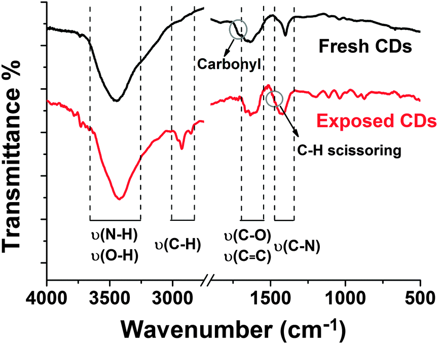 | ||
| Fig. 10 FTIR spectra of CDs before and after UV-exposure. | ||
Based on the findings we expect the following changes in the chemical surface structure of the CDs during UV exposure: the fresh CDs are likely amorphous and have no conjugated carbon based π-system as indicated by the absence of the typical G-peak in the Raman spectrum, see Fig. S5a in the ESI.† During illumination a conjugated π-system and C–H-bonds are formed as can be concluded from Raman spectroscopy (Fig. S5b, ESI†) and FTIR (Fig. 10). Moreover, a reduction of the number of functional surface groups should be an important factor. Preliminary results reveal that the nitrogen content in the bleached samples is lower than in the as-prepared ones. In UV-Vis absorption, Fig. 11a, the peak associated with the n–π* transition at 346 nm dropped as the exposure time is prolonged. And the broad peak in the visible region moved from 600–700 nm to 400–500 nm (Fig. S3 and S6 in the ESI†). The absorption transformation can be assigned to nitrogen or oxygen-based groups as well as the hybrid structure of the partial carbon skeleton and to a reduction in edge groups.51 The latter is supported by a drop in the negative zeta-potential of the CDs from about −60 mV to −30 mV upon UV irradiation, see Fig. 11b. This indicates a reduction in the number of charged groups due to UV exposure because no pH change was observed. The charged groups on the surface of the CDs should mainly be carboxylate and amide groups. Probably carboxylate groups are oxidized to carboxyl radicals which decompose to CO2 and remaining carbon radicals. The elimination of low molecular components coincides with the slight molecular weight degradation observed for the bleached CDs by AUC. The highly reactive carbon radicals can perform H-abstraction from another CD or from water and form C–H bonds.
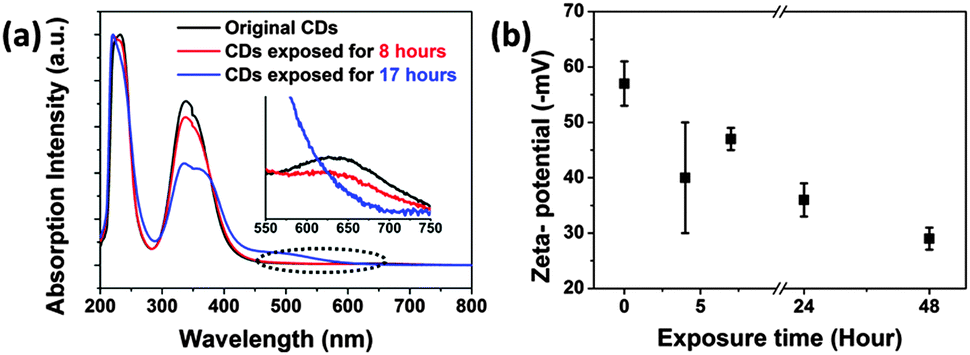 | ||
| Fig. 11 (a) Absorption spectra of CDs recorded after different UV exposure times; the illustration is an enlarged plot of the dotted line area. (b) Zeta-potential of the CD samples as a function of UV exposure time. | ||
The exact chemical structure of CDs is so far not well-known and its in-depth analysis is out of the scope of this paper. The CDs are polymerization and polycondensation products of citric acid and urea. The hydrothermal synthesis of the CDs was performed at 200 °C. Schaber et al.52 investigated the thermal decomposition of urea and have shown that at around 200 °C mainly biuret, cyanuric acid and ammelide are formed. Moreover, during the CD synthesis carbonization occurs. Thus, we expect biuret, cyanuric acid and ammelide bound to a carbon network as components of the CDs. The decomposition products of urea don't show any fluorescence. Sanji et al.53 observed fluorescence turn-on if cyanuric acid bound to tetraphenylethylene formed a complex with melamine by hydrogen bonding. XPS measurements have shown that the fluorescence quantum yield of CDs increases with the nitrogen content.10 Our own preliminary XPS results show a reduction of the nitrogen content of CDs due to photobleaching. From all these findings it can be concluded that the fluorophores of the CDs are likely complexes between cyclic urea decomposition products bound to a carbon network.
To investigate the influence of the environment on the photobleaching status of the CDs, we dispersed CDs in several solvents. As shown in Table 1, a pH shift to the alkaline range by adding ammonia or sodium hydroxide to the aqueous CD suspension has no remarkable influence on the quantum yield of fresh CDs, whereas it decreases the photostability. In the organic solvents, the fluorescence of CDs was suppressed. The centre emission wavelengths for excitation under 365 nm UV light in all solvents are in the range of blue light. The fluorescence plots and photos are shown in Fig. S7 in the ESI.†N,N-Dimethylformamide (DMF) is the best solvent to stabilize the CDs against fluorescence photobleaching. However, the fluorescence quantum yield of CDs in DMF is low. This effect is attributed to the amide group in DMF which may act as a quencher.
| Solventa | QY (Fresh) | QY (Bleached) | Stabilityb (%) |
|---|---|---|---|
| a The numbers in brackets are the center wavelengths of emission. The concentrations of CDs in every kind of solvents are 0.002 wt%. b The stability is equal to QYbleached/QYfresh. c In toluene and chloroform fluorescence bleaching cannot be measured due to the aggregation of CDs after standing for hours. | |||
| Water (pH 9.8) | 35.2% (438 nm) | 0.18% (439 nm) | 0.5 |
| Water (pH 7) | 35.1% (440 nm) | 2.9% (442 nm) | 8.3 |
| NH4OH (pH 9.8) | 34.6% (439 nm) | 0.45% (439 nm) | 1.3 |
| Ethanol | 15.7% (445 nm) | 0.16% (438 nm) | 1.0 |
| Methacrylic acid | 1.11% (447 nn) | 0.85% (450 nm) | 77 |
| Acetone | 0.75% (458 nm) | 0.23% (452 nm) | 30.7 |
| Toluene | 0.69% (430 nm) | —c | — |
| DMF | 0.52% (453 nm) | 0.56% (430 nm) | ∼100 |
| Chloroform | 0.27% (423 nm) | — | — |
From the above discussion, we conclude that intense and stable fluorescence from CDs requires well-dispersed particles and some stabilization of the molecular surface structures. We fabricated CD@PMMA (polymethyl methacrylate) composite films at a CD concentration of 0.01 wt%, which may protect the CDs from the environment. The film was transparent and fluorescent as shown in Fig. S8 in the ESI.† These thin CD@PMMA films were prepared by mixing CDs and PMMA (mass ratio is 1:10000) in acetone and the subsequent deposition of the film on glass substrates by drop or spin-coating. The CD@PMMA film emitted strong fluorescence under UV excitation (quantum yield was measured to be 2.65% shown in Fig. S9 in the ESI†), and more importantly, it was stable against UV exposure, as shown in Fig. 12. Dispersion of CDs in a PMMA film is an effective solution to prevent fluorescence photobleaching of CDs and to provide long-term stable CDs for applications in sensors.
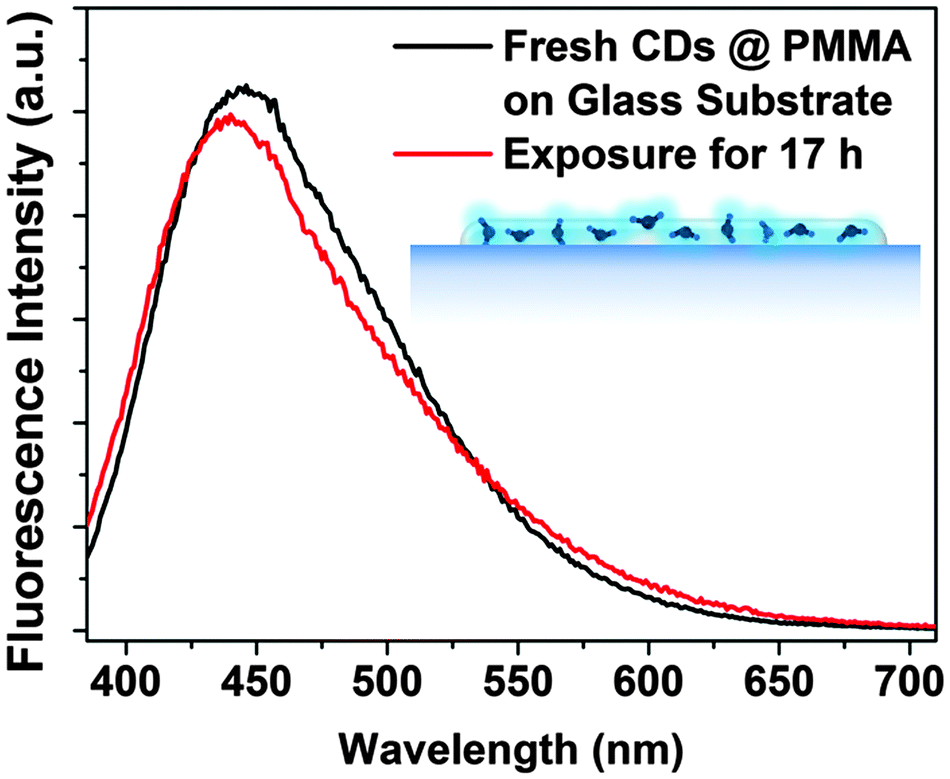 | ||
| Fig. 12 Luminescence spectra of CD@PMMA on a glass substrate before and after exposure to UV light. | ||
A comparison of our results with literatures shows that the photobleaching phenomenon is dependent on the synthetic routes and therefore on the structure of CDs and on the exposure conditions. As shown in Table 2, from the comparison of different carbon dot-like nanomaterials, the amorphous CDs from bottom-up synthesis are much easier to be bleached. But if UV or Vis exposure is intense enough, the crystalline CDs can also be degenerated in seconds.
| Number | Name | Synthetic routes | Exposure conditions | Photobleaching extent | Ref. |
|---|---|---|---|---|---|
| 1 | Carbon dots | Hydrothermal method | 2000 W UV exposure | 54.75–91.25% after 9 minutes | 17 |
| 2 | Single carbon dot | Annealing nanodiamond powders | 78 W cm−2, 561 nm laser | Single-step bleaching after 6–20 seconds | 54 |
| 3 | Luminescent carbogenic dots | Carbohydrates dehydrated | 360 nm continuous excitation | 17% after 19 hours | 16 |
| 4 | Carbon nanocrystals | Electro-oxidation | 8.3 W white Xe lamp continuous excitation | No obvious bleaching phenomenon | 14 |
| 5 | Graphitic-C3N4 quantum dot | Acid oxidation | 365 nm UV exposure | No obvious bleaching phenomenon | 15 |
| 6 | Carbon dots | Hydrothermal method or microwave method | 8 W (950 μW cm−2) 365 UV lamp; and 1.68 W 532 nm laser | ∼83% after 17 hours; and ∼50% after 13 seconds, respectively | This work |
Conclusions
In this work we synthesized CDs hydrothermally with a quantum efficiency of roughly 35%. For the first time, we studied their fluorescence photobleaching in detail and showed ways to prevent it. A decrease in fluorescence intensity by the factor of more than ten was noticeable although no obvious wavelength shift was observed during photobleaching. Photobleaching was dependent on the duration and intensity of exposure, the concentration of CDs, the presence of oxygen and the solvent. Properties before and after light exposure were characterized by UV-Vis, photoluminescence, FTIR and Raman spectroscopy as well as by AUC and zeta-potential measurements. Photobleaching leads to a slight decrease in mass and size indicating a loss of molecular structure. Although the specific chemical structure is not yet clear, we demonstrated that a change in the surface status must be responsible for the observed photobleaching of CDs. In order to stabilize the as-prepared CDs we showed that sealing of CDs in a polymer matrix such as PMMA leads to long-term photostability opening many possibilities for future applications.Acknowledgements
The German Science Foundation (DFG) is acknowledged by the authors for financial support through project “PE 427/28-1” and SFB 953 “Synthetic Carbon Allotropes”. This research was in part supported by NSF grant ACI-1339649 to Borries Demeler from University of Texas, USA, and computer time on XSEDE resources was funded by NSF allocation grant TG-MCB070039N to B.D.Notes and references
- X. T. Zheng, A. Ananthanarayanan, K. Q. Luo and P. Chen, Small, 2015, 11, 1620–1636 CrossRef CAS PubMed.
- S. Zhu, Y. Song, X. Zhao, J. Shao, J. Zhang and B. Yang, Nano Res., 2015, 8, 355–381 CrossRef CAS.
- C. Xie, B. Nie, L. Zeng, F.-X. Liang, M.-Z. Wang, L. Luo, M. Feng, Y. Yu, C.-Y. Wu, Y. Wu and S.-H. Yu, ACS Nano, 2014, 8, 4015–4022 CrossRef CAS PubMed.
- G. E. LeCroy, S. K. Sonkar, F. Yang, L. M. Veca, P. Wang, K. N. Tackett, J.-J. Yu, E. Vasile, H. Qian, Y. Liu, P. G. Luo and Y.-P. Sun, ACS Nano, 2014, 8, 4522–4529 CrossRef CAS PubMed.
- J. Ge, Q. Jia, W. Liu, L. Guo, Q. Liu, M. Lan, H. Zhang, X. Meng and P. Wang, Adv. Mater., 2015, 27, 4169–4177 CrossRef CAS PubMed.
- B. Kong, A. Zhu, C. Ding, X. Zhao, B. Li and Y. Tian, Adv. Mater., 2012, 24, 5844–5848 CrossRef CAS PubMed.
- H. Tao, K. Yang, Z. Ma, J. Wan, Y. Zhang, Z. Kang and Z. Liu, Small, 2012, 8, 281–290 CrossRef CAS PubMed.
- A. Ananthanarayanan, X. Wang, P. Routh, B. Sana, S. Lim, D.-H. Kim, K.-H. Lim, J. Li and P. Chen, Adv. Funct. Mater., 2014, 24, 3021–3026 CrossRef CAS.
- H. Sun, N. Gao, L. Wu, J. Ren, W. Wei and X. Qu, Chem. – Eur. J., 2013, 19, 13362–13368 CrossRef CAS PubMed.
- Z. Qian, J. Ma, X. Shan, H. Feng, L. Shao and J. Chen, Chem. – Eur. J., 2014, 20, 2254–2263 CrossRef CAS PubMed.
- Z. Huang, Y. Shen, Y. Li, W. Zheng, Y. Xue, C. Qin, B. Zhang, J. Hao and W. Feng, Nanoscale, 2014, 6, 13043–13052 RSC.
- X. Fang, M. Li, K. Guo, J. Li, M. Pan, L. Bai, M. Luoshan and X. Zhao, Electrochim. Acta, 2014, 137, 634–638 CrossRef CAS.
- P. Gao, K. Ding, Y. Wang, K. Ruan, S. Diao, Q. Zhang, B. Sun and J. Jie, J. Phys. Chem. C, 2014, 118, 5164–5171 CAS.
- Q.-L. Zhao, Z.-L. Zhang, B.-H. Huang, J. Peng, M. Zhang and D.-W. Pang, Chem. Commun., 2008, 5116–5118 RSC.
- X. Zhang, H. Wang, H. Wang, Q. Zhang, J. Xie, Y. Tian, J. Wang and Y. Xie, Adv. Mater., 2014, 26, 4438–4443 CrossRef CAS PubMed.
- H. Peng and J. Travas-Sejdic, Chem. Mater., 2009, 21, 5563–5565 CrossRef CAS.
- S. Zhu, Q. Meng, L. Wang, J. Zhang, Y. Song, H. Jin, K. Zhang, H. Sun, H. Wang and B. Yang, Angew. Chem., 2013, 125, 4045–4049 CrossRef.
- Z. Yang, M. Xu, Y. Liu, F. He, F. Gao, Y. Su, H. Wei and Y. Zhang, Nanoscale, 2014, 6, 1890–1895 RSC.
- D. Qu, M. Zheng, P. Du, Y. Zhou, L. Zhang, D. Li, H. Tan, Z. Zhao, Z. Xie and Z. Sun, Nanoscale, 2013, 5, 12272–12277 RSC.
- J. Wang, Z. Zhang, S. Zha, Y. Zhu, P. Wu, B. Ehrenberg and J.-Y. Chen, Biomaterials, 2014, 35, 9372–9381 CrossRef CAS PubMed.
- X. Zhou, P. Ma, A. Wang, C. Yu, T. Qian, S. Wu and J. Shen, Biosens. Bioelectron., 2015, 64, 404–410 CrossRef CAS PubMed.
- C. Wang, Z. Xu and C. Zhang, ChemNanoMat, 2015, 1, 122–127 CrossRef CAS.
- V. Strauss, J. T. Margraf, C. Dolle, B. Butz, T. J. Nacken, J. Walter, W. Bauer, W. Peukert, E. Spiecker, T. Clark and D. M. Guldi, J. Am. Chem. Soc., 2014, 136, 17308–17316 CrossRef CAS PubMed.
- X. Zhai, P. Zhang, C. Liu, T. Bai, W. Li, L. Dai and W. Liu, Chem. Commun., 2012, 48, 7955–7957 RSC.
- R. Liu, D. Wu, S. Liu, K. Koynov, W. Knoll and Q. Li, Angew. Chem., 2009, 121, 4668–4671 CrossRef.
- Y. Guo, Z. Wang, H. Shao and X. Jiang, Carbon, 2013, 52, 583–589 CrossRef CAS.
- J. Tang, B. Kong, H. Wu, M. Xu, Y. Wang, Y. Wang, D. Zhao and G. Zheng, Adv. Mater., 2013, 25, 6569–6574 CrossRef CAS PubMed.
- Q. Liu, B. Guo, Z. Rao, B. Zhang and J. R. Gong, Nano Lett., 2013, 13, 2436–2441 CrossRef CAS PubMed.
- Q. Wang, H. Zheng, Y. Long, L. Zhang, M. Gao and W. Bai, Carbon, 2011, 49, 3134–3140 CrossRef CAS.
- Z.-A. Qiao, Y. Wang, Y. Gao, H. Li, T. Dai, Y. Liu and Q. Huo, Chem. Commun., 2009, 8812–8814 Search PubMed.
- R. Ye, C. Xiang, J. Lin, Z. Peng, K. Huang, Z. Yan, N. P. Cook, E. L. G. Samuel, C.-C. Hwang, G. Ruan, G. Ceriotti, A.-R. O. Raji, A. A. Martí and J. M. Tour, Nat. Commun., 2013, 4, 2943 Search PubMed.
- W. R. Jackson, C.-Y. Choi, W. R. Bergmark and G. Jones II, J. Phys. Chem., 1985, 89, 294–300 CrossRef.
- H. Zheng, Q. Wang, Y. Long, H. Zhang, X. Huang and R. Zhu, Chem. Commun., 2011, 47, 10650–10652 RSC.
- W. Kwon, S. Do, J. Lee, S. Hwang, J. K. Kim and S.-W. Rhee, Chem. Mater., 2013, 25, 1893–1899 CrossRef CAS.
- J. Walter, K. Löhr, E. Karabudak, W. Reis, J. Mikhael, W. Peukert, W. Wohlleben and H. Cölfen, ACS Nano, 2014, 8, 8871–8886 CrossRef CAS PubMed.
- O. Kratky, H. Leopold and H. Stabinger, Methods Enzymol., 1973, 27, 98–110 CAS.
- E. Brookes, W. Cao and B. Demeler, Eur. Biophys. J., 2010, 39, 405–414 CrossRef PubMed.
- B. Demeler and E. Brookes, Colloid Polym. Sci., 2008, 286, 129–137 CAS.
- S. Qu, X. Wang, Q. Lu, X. Liu and L. Wang, Angew. Chem., Int. Ed., 2012, 51, 12215–12218 CrossRef CAS PubMed.
- Y. Li, Y. Zhao, H. Cheng, Y. Hu, G. Shi, L. Dai and L. Qu, J. Am. Chem. Soc., 2012, 134, 15–18 CrossRef CAS PubMed.
- L. Lin, M. Rong, S. Lu, X. Song, Y. Zhong, J. Yan, Y. Wang and X. Chen, Nanoscale, 2015, 7, 1872–1878 RSC.
- Y. Dong, R. Wang, G. Li, C. Chen, Y. Chi and G. Chen, Anal. Chem., 2012, 84, 6220–6224 CrossRef CAS PubMed.
- H. Nie, M. Li, Q. Li, S. Liang, Y. Tan, L. Sheng, W. Shi and S. X.-A. Zhang, Chem. Mater., 2014, 26, 3104–3112 CrossRef CAS.
- Y. Liu, N. Xiao, N. Gong, H. Wang, X. Shi, W. Gu and L. Ye, Carbon, 2014, 68, 258–264 CrossRef CAS.
- R. Andreozzi, V. Caprio, A. Insola and R. Marotta, Catal. Today, 1999, 53, 51–59 CrossRef CAS.
- E. J. Rosenfeldt, K. G. Linden, S. Canonica and U. Gunten, Water Res., 2006, 40, 3695–3704 CrossRef CAS PubMed.
- B. B. Benson and D. Krause Jr, J. Chem. Phys., 1976, 64, 689–709 CrossRef CAS.
- A. C. Ferrari and J. Robertson, Catal. Today, 2004, 362, 51–59 Search PubMed.
- L. M. Malard, M. A. Pimenta, G. Dresselhaus and M. S. Dresselhaus, Phys. Rep., 2009, 473, 51–87 CrossRef CAS.
- M. S. Dresselhaus, A. Jorio, A. G. Souza Filho and R. Saito, Philos. Trans. R. Soc., A, 2010, 368, 5355–5377 CrossRef CAS PubMed.
- Y. Wang, S. Kalytchuk, Y. Zhang, H. Shi, S. V. Kershaw and A. L. Rogach, J. Phys. Chem. Lett., 2014, 5, 1412–1420 CrossRef CAS PubMed.
- P. M. Schaber, J. Colson, S. Higgins, D. Thielen, B. Anspach and J. Brauer, Thermochim. Acta, 2004, 424, 131–142 CrossRef CAS.
- T. Sanji, M. Nakamura, S. Kawamata, M. Tanaka, S. Itagaki and T. Gunji, Chem. – Eur. J., 2012, 18, 15254–15257 CrossRef CAS PubMed.
- S. K. Das, Y. Liu, S. Yeom, D. Y. Kim and C. Richards, Nano Lett., 2014, 14, 620–625 CrossRef CAS PubMed.
Footnote |
| † Electronic supplementary information (ESI) available: Absorption and fluorescence spectra of aqueous suspensions of CDs (S1); 3D fluorescence plots of CDs synthesized at different temperatures (S2); dependence of the absorbance of CDs on concentration, Lambert–Beer-plots and an explanation of a decrease in fluorescence intensity by re-absorption (S3); determination of the fluorescence quantum yield of the CDs using the slope method and fluorescence quantum yield as a function of UV exposure time (S4); investigation of fluorescence photobleaching by Raman spectroscopy (S5); absorption spectra of CDs after UV exposure (S6); fluorescence spectra and photos of as-prepared as well as of UV exposed CDs dispersed in different solvents (S7); a photo and 3D fluorescence plot of a film of CDs in PMMA before and after exposure to UV (S8); determination of the fluorescence quantum yield of CD@PMMA (S9). See DOI: 10.1039/c5cp04942c |
| This journal is © the Owner Societies 2016 |