DOI:
10.1039/C5CE01946J
(Paper)
CrystEngComm, 2016,
18, 316-327
In-depth mesocrystal formation analysis of microwave-assisted synthesis of LiMnPO4 nanostructures in organic solution†
Received
2nd October 2015
, Accepted 26th November 2015
First published on 27th November 2015
Abstract
In the present work, we report on the preparation of LiMnPO4 (lithiophilite) nanorods and mesocrystals composed of self-assembled rod subunits employing microwave-assisted precipitation with processing times on the time scale of minutes. Starting from metal salt precursors and H3PO4 as phosphate source, single-phase LiMnPO4 powders with grain sizes of approx. 35 and 65 nm with varying morphologies were obtained by tailoring the synthesis conditions using rac-1-phenylethanol as solvent. The mesocrystal formation, microstructure and phase composition were determined by electron microscopy, nitrogen physisorption, X-ray diffraction (including Rietveld refinement), dynamic light scattering, X-ray absorption and X-ray photoelectron spectroscopy, and other techniques. In addition, we investigated the formed organic matter by gas chromatography coupled with mass spectrometry in order to gain a deeper understanding of the dissolution–precipitation process. Also, we demonstrate that the obtained LiMnPO4 nanocrystals can be redispersed in polar solvents such as ethanol and dimethylformamide and are suitable as building blocks for the fabrication of nanofibers via electrospinning.
Introduction
Among nanostructured materials such as spinel-type oxides and polyanionic compounds, lithium metal phosphates have attracted significant interest over the last decade in electrochemical energy storage technologies.1–5 Low-cost materials and non-toxic compounds are increasingly discussed as desirable for the fabrication of sustainable energy storage materials.6 Lithium ion batteries (LIBs) are still one of the most promising sectors of energy storage systems, because of numerous beneficial properties such as the non-toxicity of the used compounds while the deposit is extremely high.6,7 While numerous inorganic host materials allow reversible insertion/desertion of Li among the cathode materials, the phospho-olivine LiMnPO4 (Pmnb, a = 0.61 nm, b = 1.046 nm, c = 0.474 nm) and derivatives thereof, such as triphylite (LiFePO4) and heterosite (Fe0.65Mn0.35PO4), have gained significant attention.8 The unit cell of LiMnPO4 is shown in Fig. S1.† In this structure, lithium and manganese ions are located on octahedral 4(a) and 4(c) sites (Wyckoff notation), respectively, whereas the phosphorous ions are situated on tetrahedral 4(c) sites.8 A serious problem is the low electrical conductivity of these materials. In order to improve their conductivity, hybrid materials consisting of LiMnPO4 coupled with a conductive material and doping with high valent metal ions (e.g., Nb5+, Zr4+) to increase the electron concentration are proposed solutions. It was shown that carbon-coated LiFePO4 particles exhibit a higher conductivity than uncoated ones being beneficial for battery applications.6 Additionally, it was proved that a carbon coating can prevent volumetric stress during cyclization.9,10 In the past years, different strategies for the synthesis of LiMnPO4 were reported, for both bulk and nanoscaled material. The synthesis of lithium metal phosphates (LiMPO4) via solid-state reactions at elevated temperatures such as 800 °C for up to 2 days has been described in a number of publications.11–14 It was already reported in 1997 that lithium can be extracted and inserted into these compounds.11 These syntheses lead to particles with an average diameter of several hundred nanometer.13 Also pulsed laser deposition was applied at 500 °C in order to synthesize LiMPO4 such as LiFePO4.15 A sol–gel based citric acid route still required temperatures slightly lower than 600 °C.16 Even lower temperatures in the range of 300 °C were applied in a spray pyrolysis-assisted synthesis.17 LiMnPO4 has also been prepared in ionic liquids (ILs) with long reaction times. It was found that 250 °C is the minimum temperature for the formation of LiMnPO4 in ILs.18 Theoretical calculations predict that the reduction of grain size is an unavoidable criterion for the usage of LiMnPO4 as an electrode material. In calculations performed by Siddique et al. active LiMPO4 (M = Mn, Co, Ni) material possessing grain sizes below 20 nm do not show a loss of capacity due to higher cycling rates which is supposed to be caused by a shorter lithium ion diffusion length.19 Therefore the entire active particle can be addressed within shorter time considering same diffusion rates. The calculations have revealed the importance of both smaller grain and particle sizes, since only the capacity of particles with sizes below 20 nm is expected to show no dependency on the cycling rate. The theoretical capacity of about 160 mA h g−1 of 20 nm LiFePO4 can be conserved even at 2C whereas 50 nm particles show a decay of the capacity to about 100 mA h g−1 at 2C.19 LiMnPO4 is even more interesting as the theoretical energy density is higher than that of LiFePO4.13 Recently, a microwave-assisted synthesis of different lithium transition metal phosphates was reported by Bilecka et al. In the case of LiMnPO4 and LiFePO4, grain sizes of 200 nm or 50 nm were achieved at a synthesis temperature of 180 °C. The resulting particles were described as mesocrystals consisting of subunits.20 This synthesis is based on benzyl alcohol which is supposed to be both solvent and reaction partner of the metal salt precursors. Also, it allows the control of particle size, surface properties and assembly behavior in some cases.21,22 Recently, it was shown that also benzylamine can serve as a suitable solvent to produce LiMPO4.23 Intriguingly, the mentioned aromatic solvents promote the growth of LiMnPO4 platelets either in [100]Pnma (benzyl alcohol) or in [010]Pnma (benzylamine) direction.23,24
The present work is devoted to both developing microwave-based synthetic strategies for further decreasing the size of LiMnPO4 nanoparticles, as well as to the in-depth analysis of the intricate crystallization mechanism of micron sized particles and the origin of the outer appearance already mentioned by Bilecka et al.20 Based on the results obtained utilizing benzyl alcohol, providing particle sizes of about several hundred nanometers, in the present study rac-1-phenylethanol was used instead. It is noted that this aromatic alcohol has a boiling point (∼204 °C) comparable to benzyl alcohol and a somewhat higher heating rate under microwave radiation, but exhibits much better solvent properties in the dissolution–precipitation process, which pave the way to control the morphology and grain size of LiMnPO4. Moreover, this “low” temperature synthesis also prevents the oxidation of Mn2+ to Mn3+. Since microwave-assisted synthesis of nanoparticles benefits from a better control of reaction conditions, it additionally allows the in-depth investigation of the influence of reaction conditions on the crystallization mechanism and reaction times in the time scale of minutes. In addition to the development of an alternative synthesis based on rac-1-phenylethanol, in our study the crystallization mechanism of LiMnPO4 was studied in-depth by X-ray diffraction (XRD) and transmission electron microscopy (TEM) to obtain complementary information on different length scales. The microwave-reaction was interrupted at certain stages of the synthesis to perform ex-situ XRD and SEM investigations. By such ex-situ experiments on specimen obtained by the abortion of the reaction, fine mechanistic details could be revealed on the evaluation of the crystallinity and the intricate morphology of the nanocrystals. These investigations were complemented by thermogravimetric analysis-mass spectrometry (TGA-MS) and chromatography-mass spectrometry (GC-MS), providing insights into the reaction mechanism and the role of rac-1-phenylethanol. Thus, our study aims at a comprehensive understanding of the reaction mechanism on the molecular scale and of its influence on the crystallization, as well as the evolution of the crystal morphology with respect to the attachment of small crystallites into larger particles. In addition, X-ray photoelectron spectroscopy (XPS) and X-ray absorption spectroscopy (XAS) were used to clarify both the surface composition and local order of the metal atoms in the obtained nanorods and mesocrystals, respectively.
Experimental
Materials
Anhydrous lithium chloride (≥99%), manganese(II) acetate (98%), phosphoric acid (99%), dimethylformamide (99.8%) and polyacrylonitrile (referred to as PAN; Mw 150.000 g mol−1) were purchased from Sigma Aldrich. Rac-1-phenylethanol (98%) was purchased from ABCR, while ethanol (99.8%) and diethyl ether (99%) were purchased from VWR. Nitric acid (≥69%) used for ICP analysis was purchased from PROLABO (Italy). IV-ICPMS-71A (10 mg L−1) was used as multi-element ICP-MS calibration standard and purchased from Inorganic Ventures (USA). All solutions have been prepared in MilliQ ultrapure water (resistivity 18.2 MΩ cm−1) obtained with a Millipore Plus System.
Microwave-synthesis of LiMnPO4
In a representative synthesis, 43.2 mg (1.02 mmol) of LiCl was dissolved in 3 mL rac-1-phenylethanol. To the resulting solution, 175.5 mg (1.02 mmol) of Mn(CH3CO2)2 dissolved in 12 mL rac-1-phenylethanol were added and sonicated for 10 min. Then, the obtained mixture was transferred to a 30 mL borosilicate vial, followed by adding a solution of 100 mg (1.02 mmol) anhydrous H3PO4 and 2 mL rac-1-phenylethanol. After sealing the glass vial, the precursor solution was rapidly heated to 200 °C under microwave irradiation and kept there for 15 min. The stirring rate was set to 300 rpm and kept constant during the microwave treatment. After quenching the solution with compressed air to 55 °C, the precipitate was collected by centrifugation at 6000 rpm and washed twice with ethanol and diethyl ether. Lastly, the obtained powder was dried in air at 80 °C for 12 h. Table 1 summarizes precursor masses for each type of LiMnPO4 material prepared in this work.
Table 1 Recipes for the synthesis of LiMnPO4 nanocrystals
| Batch sizea |
Mn(CH3CO2)2 |
LiCl |
H3PO4 |
Synthesis time |
Grain size |
|
In all synthesis protocols, 17 mL of rac-1-phenylethanol is used.
|
| 60 mmol L−1 |
176.5 mg |
43.2 mg |
100.0 mg |
11 min |
∼65 nm |
| 30 mmol L−1 |
88.2 mg |
21.6 mg |
50.0 mg |
15 min |
∼37 nm |
| 20 mmol L−1 |
58.8 mg |
14.4 mg |
33.3 mg |
21 min |
∼35 nm |
Fabrication of carbon-fiber composites
In a typical electrospinning experiment, 53 mg LiMnPO4 nanoparticles were dispersed thoroughly in 1 g of a solution of 8 wt% PAN in dimethylformamide (5 wt%). This solution was fed through a metallic needle by a syringe pump (Harvard Apparatus, 11Plus MA1 70-2208) at the rate of 0.7 mL h−1. Permissible relative humidity can range from 20–60% without major effects on the fiber quality. An electric field strength of 0.1 kV cm−1 was applied between the needle and the collector and a voltage of −2 kV between the collector and ground potential. The electrospun fiber mat was stabilized in ambient air at 200 °C for 30 minutes. Next, the fibers were heated with a ramp of 100 °C h−1 under a reducing atmosphere (90% Ar and 10% H2) to 850 °C and kept there for 8 h followed by quenching to room temperature.
Characterization
Microwave-assisted syntheses were carried out employing a Monowave 300 reactor (f = 2.45 GHz) from Anton Paar Germany equipped with an 850 W magnetron. The temperature was controlled by a Ruby-thermometer (fiber-optic probe) mounted in the center of a glass vial. Pressure sensing was accomplished by a hydraulic sensor system. Scanning electron microscopy (SEM) micrographs were taken with a MERLIN instrument from Carl Zeiss operated with a working distance of approx. 5 mm and 2 kV acceleration voltage. Transmission electron microscopy (TEM) micrographs and electron diffraction was performed on a Philips EM30 using an acceleration voltage of 300 kV. Wide-angle X-ray diffraction (WAXD) measurements were carried out on an X'Pert PRO diffractometer from PANalytical instruments using Cu Kα radiation. Rietveld refinement was performed with Fullprof software using 6 coefficient polynomial background and Thompson–Cox-pseudo-Voigt peak function. The grain size was calculated via anisotropic Lorentzian size broadening approach.25 UV-visible spectra via diffuse reflectance spectroscopic measurements were recorded on a Perkin-Elmer Lambda 750 UV-vis-NIR spectrophotometer equipped with a Praying-Mantis diffuse reflectance accessory. Spectralon type DRP-SPR from Harrick Scientific Products was employed as a standard. The collected diffuse reflectance spectra are changed into absorption spectra according to the Kubelka–Munk remission function F(R) = (1 − R)2/2R, in which F(R) is the Kubelka–Munk function and R is the diffuse reflectance of the sample for "infinite" thickness relative to the reflectivity of the white standard. The optical band gap (Eg) is obtained by the plot of (F(R)·hν)nvs. photon energy (hν), where n = 1/2 and n = 2 characterize an indirect or direct optical transition, respectively. Thermogravimetric measurements were performed on a Netzsch STA 409 PC at a heating rate of 5 °C min−1. The thermobalance was coupled to a Balzers QMG 421 quadrupole mass spectrometer. The ionization energy was 70 eV. Infrared spectra were measured on a Bruker IFS 25 FTIR spectrometer. GC-MS analyses were conducted using an Agilent 5973 MSD with 6890 gas chromatograph. Metal compositions were determined by using an inductively coupled plasma connected to a mass spectrometer (ICP-MS) Agilent Technologies 7700× ICP-MS system (Agilent Technologies International, USA). The MS detector was equipped with an octupole collision cell operating in kinetic energy discrimination mode for the removal of polyatomic interferences and argon-based interferences. All instrument parameters were optimized daily while aspirating the tuning solution containing 140Ce, 7Li, 205Tl and 89Y (Agilent Technologies, UK). A 50 μg L−1 solution of 45Sc and 115In (Aristar®, BDH, UK) prepared in 5% (w/w) nitric acid was used as an internal standard through addition to the sample solution via a T-junction. The material was mineralized by treating a proper amount of the samples (in the order of 15 mg) with 5 g of a solution consisting of 69% HNO3. A Microwave Digestion System (CEM EXPLORER SP-D PLUS) was used for the acid digestion. The operative conditions were Tmax = 200 °C, pressure = 300 psi, and power = 250 W. The digestion solution was diluted with a 5% (w/w) HNO3 aqueous solution. X-ray photoelectron spectroscopy (XPS) data were acquired on a Perkin-Elmer Φ5600ci spectrometer with nonmonochromatic Al Kα X-ray source (1486.6 eV) operating at 250 W. The working pressure was <5·10−8 Pa. We performed a calibration of the spectrometer using the binding energy (BE) of the Au 4f7/2 signal at 83.9 eV. The C 1s signal from adventitious carbon (C–C peak) at BE of 284.6 eV was used as energy reference to correct for charging. Elemental analyses were carried out by using the software Multipak. X-ray absorption measurements at Mn K-edge (>6537 eV) were performed at Italian beamline BM08 of the European Synchrotron Radiation Facility (ESRF), Grenoble, France, in 7/8-bunch mode (200 mA). For energy selection a Si(311) double-crystal monochromator was used. Spectra at Mn K-edge were collected in transmission mode, using two ionization chambers placed upstream and downstream of the sample. Prior to measurements, samples were finely ground into a homogeneous pellets using cellulose as a dispersant. Data reduction and analysis were performed by using the freeware package Demeter.26 The amplitude factor (S02) was calibrated against metallic Mn foil and determined to be 0.9.
3. Results and discussion
In this work, highly crystalline LiMnPO4 nanostructures were fabricated by solution-phase precipitation involving Mn(CH3CO2)2, LiCl and H3PO4 (solid) as starting materials in combination with rac-1-phenylethanol as solvent. In a typical synthesis, both metal salt precursors are separately dissolved by sonication in dry rac-1-phenylethanol (bp 204 °C) at 30–50 °C and combined into one solution. Then, a freshly prepared solution containing H3PO4 and rac-1-phenylethanol is added to the previous mixture and rapidly heated to 200 °C employing a microwave reactor (Monowave 300 from Anton Paar, Germany) while gently stirring.
In order to elucidate the intricate crystallization pathway in solution, both the liquid reaction mixture and the formed precipitates were investigated after various reaction times by gas chromatography mass spectrometry (GC-MS) and powder X-ray diffraction (PXRD), respectively. A series of XRD patterns collected after different reaction times are shown in Fig. 1. It can be seen that phase-pure LiMnPO4 with orthorhombic space group Pmnb (ICSD collection code 25834)‡ is obtained after only 11 min at 200 °C. It is worthwhile noting that conventional hydrothermal routes require much longer synthesis times, i.e., several hours under comparable temperature conditions.27,28 An average grain size of (65 ± 5) nm was determined by applying the Rietveld refinement method (see refinement data in Table S1†). Interestingly, this result is an improvement on previous attempts from Bilecka et al. in terms of generating nanograins of diameters less than 100 nm employing microwave-assisted synthesis.20 However, even smaller nanograins are required to improve the electrochemical properties. We will return to this point after discussion of the precipitation changes which occur in the course of the synthesis. To gain a clearer picture of the precipitation mechanism, we examined the formed precipitates after different synthesis times by XRD. After mixing the precursor solution with dissolved H3PO4, a fine white to pale brown precipitate appears, which mostly consists of different manganese derivatives, e.g., crystalline hydrated manganese phosphates (Mn3(PO4)2 × nH2O; n = 3 and 7, Mn6(PO4)4 × H2O), ultraphosphate [Mn(P4O11)], cyclotetraphosphate [Mn2(P4O12)] and manganese chloride dihydrate (MnCl2 × 2H2O), to mention only a few, as evidenced by XRD analysis. Also, Li3PO4 (lithiophosphate) is formed after heating the solution to 200 °C, as can be seen from the XRD data. At first glance, this result is not surprising considering that LiCl readily reacts with H3PO4 in a metathesis-like reaction to Li3PO4 and HCl. The incipient formation of Mn3(PO4)2 is attributable to a ligand exchange reaction of the acetate groups, while Mn(P4O11) and Mn2(P4O12) are formed due to protonation and dehydration reactions of tetrahedral PO4 groups with hydrochloric acid, which favors the production of the latter compounds.29 Hereinafter, the most important reaction pathways are described below:
| | | 3Mn(CH3CO2)2 + 2H3PO4 → Mn3(PO4)2 + 6CH3COOH | (1) |
| | | 2Mn3(PO4)2 × 3H2O ⇆ Mn6(PO4)4 × H2O + 5H2O | (2) |
| | | 3LiCl + H3PO4 → Li3PO4 + 3HCl | (3) |
| | | 2Mn(CH3CO2)2 + 4H3PO4 + 8HCl → Mn2(P4O12) + 4CH3COOH + 4H2O + 8HCl | (4a) |
| | | 4PO43− + 8HCl → P4O124− + 4H2O + 8Cl− | (4b) |
| | | Mn(CH3CO2)2 + 4H3PO4 + 10HCl → Mn(P4O11) + 2CH3COOH + 5H2O + 10HCl | (5a) |
| | | 4PO43− + 10HCl → P4O112− + 5H2O + 10Cl− | (5b) |
| | | Mn(CH3CO2)2 + 2HCl + 2H2O → MnCl2 × 2H2O + 2CH3COOH | (6) |
In the course of the microwave treatment at 200 °C, the intermediate phases are dissolved with increasing time which we attribute to a continuous dissolution–precipitation process during the formation of crystalline LiMnPO
4. In order to obtain deeper insights into the dissolution process, we analyzed the organic solution after completion of the synthesis by GC-MS (see Fig. S3 in ESI
†). Overall, four reaction products were found, namely 1-phenylethyl acetate, 1-phenylethyl chloride, styrene and bis(α-methylbenzyl) ether, as shown in Table S2.
† Their formation can be explained by various acid-catalyzed reactions of 1-phenylethanol,
i.e. esterification, nucleophilic substitution, elimination and etherification reactions:
| | | PhCH(CH3)OH + CH3COOH → PhCH(CH3)–O–(COCH3) + H2O | (7) |
| | 2PhCH(CH3)OH + HCl ⇆ PhCH(CH3)Cl + PhCH![[double bond, length as m-dash]](https://www.rsc.org/images/entities/char_e001.gif) CH2 + 2H2O CH2 + 2H2O | (8) |
| | | 2PhCH(CH3)OH + PhCH(CH3)Cl → [PhCH(CH3)2]O + HCl | (9) |
In this context, we assume that both 1-phenylethyl chloride and styrene play major roles during the dissolution process at elevated temperatures, because they can reversibly release and accept back HCl (see
eqn (3) and
(8)) which is proposed to be vital for the dissolution rate of poorly soluble manganese and lithium phosphates by forming of more soluble chloride salts.
30 To improve the preparation procedure, we decided to reduce the precursor concentration from 60 mmol L
−1 down to 30 mmol L
−1 and 20 mmol L
−1 in order to avoid and limit the particle growth of LiMnPO
4. In fact, grain sizes of (37 ± 3) nm and (35 ± 5) nm were achieved by dilution of the precursors in solution and increasing the synthesis time, as indicated by XRD (see
Fig. 1c and d). Based on Rietveld refinement we found a higher occupation number on octahedral 4(a) sites, which indicates an irregular occupation of Li sites by Mn
2+ ions. Moreover, it was also found that the Mn
2+ disorder increases with decreasing grain size. However, no impurities remain after the dissolution–precipitation process as evidenced by XRD. This is a remarkable result, since it allows control of the grain size of LiMnPO
4 to a certain degree merely by changing the precursor concentration in
rac-1-phenylethanol as a proper solvent. Also, no dependency of the calculated grain sizes on the scattering vector/peak order could be observed in any of the samples (see Fig. S2
†).
 |
| | Fig. 1 (a) XRD patterns (undiluted approach with 60 mmol L−1 precursor concentration) recorded after reaction times of 0 min (A), 3 min (B), 5 min (C), 7 min (D), 9 min (E) and 11 min (F), respectively. (b) Refined diffraction pattern of (F). (c) Refined diffraction pattern of LiMnPO4 after a reaction time of 15 min and two-fold dilution of the LiMnPO4 precursors (30 mmol L−1 precursor concentration). (d) Refined diffraction pattern of LiMnPO4 after a reaction time of 21 min and three-fold dilution of the LiMnPO4 precursors (20 mmol L−1 precursor concentration). Observed intermediate phases are indicated by different symbols: # (MnCl2 × 2H2O; ICSD code 15596), □ (Li3PO4; ICSD code 77095), * (Mn(P4O11); ICSD code 400840), Δ (Mn2(P4O12); ICSD code 412558), ζ Mn6(PO4)4 × 1H2O; ICSD code 412152). | |
Apart from the crystalline structure, we also investigated the morphology and phase composition in more detail by SEM, TEM, DLS, physisorption, TG-MS, FTIR, XPS, XAS, and UV-vis-NIR. In order to gain deeper insights into the precipitation process we performed extensive SEM investigations of the crystalline powders. Overall, three synthesis approaches have been investigated to visualize the powder morphology after various time intervals. As can be seen from the SEM images in Fig. 2, the powder samples of the undiluted approach (60 mmol L−1) possess a nanoplatelet structure, which is often observed under hydrothermal and solvothermal conditions.31–33 Moreover, it can be seen that nanorods were initially formed during the early stages of the synthesis. Later, the rods assemble into subunits of micrometer sized platelets due to Ostwald ripening.34,35 Based on these observations, it is obvious that the primary particle size is several orders of magnitude larger than the determined grain size. In consideration of the SEM data, we can conclude that the platelet crystals are just intermediates which aggregate to micron sized particles due to their high surface energy as can be seen in Fig. 2f.36 The mesocrystals formation can be described as follows. First, small nanorods are formed, which aggregate to loop-like particle forms. Subsequently, these loops are filled with further particles while the original rods grow. With increasing synthesis time, practically only filled platelet particles can be found in the samples. Moreover, the particles grow perpendicular to the (primary) particle axis and take on a virtually rectangular shape which corresponds more to the theoretical Wulff-shape.37 This may indicate a transition between kinetic driven formation mechanism in the early stages of the reaction and thermodynamically driven formation after a prolonged synthesis time.34,35 Also, it can be pointed out that the domains continue to grow, so that the particles look like single crystals (Fig. 2f). Fig. 2d shows a particle which consists of two crossed particle aggregates. These observations show that the mesocrystal formation mechanism must involve loop-like particles, which assemble into a ring-shaped structure. The scheme in Fig. 2g illustrates the observed formation mechanism. In the case of the two diluted approaches (batch size 30 mmol L−1 and 20 mmol L−1), we have been able to prevent aggregation to a large extent thus preserving the initial nanorod structure. In Fig. 3 SEM, TEM and SAED data of weakly aggregated LiMnPO4 nanorods are presented. As shown here, the synthesis was terminated before the formation of the platelets could take place. Furthermore, the synthesis time was sufficiently long to obtain single-phase LiMnPO4. Owing to the dilution, the synthesis time had to be slightly increased and, intriguingly, aggregation to micron-sized particles was completely suppressed. Also, TEM images evidence the high crystallinity of the particles and indicate a non-crystalline surface layer of 1–2 nm (see Fig. 3e), which is supposed to be Li0.831Mn1.085PO4 as indicated by XPS (see Table S3†). Additionally, the SAED pattern indicates that the particles seem to expose the (100)Pmnb planes which is beneficial for lithium ion diffusion.38 According to theoretical calculations lithium extraction/insertion from/into the outermost layers of the planes possess the lowest redox potential of 3.2 V and these planes should therefore be exposed because of a lower surface energy compared to other surfaces.37 The aspect ratio of the particles was determined from SEM images, measuring the length of both main axes (see Fig. S4† for size distributions). Both particle types show a short axis of about 120 nm and a longer axis of about 410 nm. The aspect ratio in both cases can be calculated to 0.29 in the case of 30 mmol L−1 and 0.24 for 20 mmol L−1.
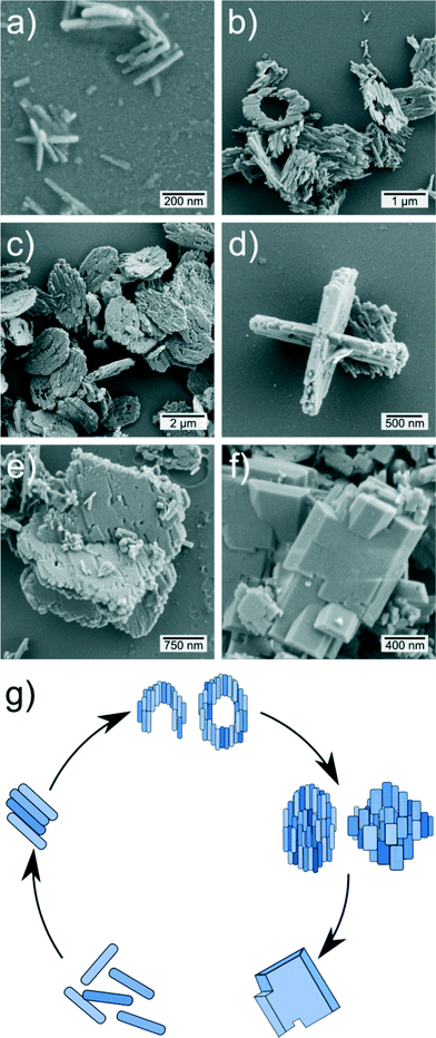 |
| | Fig. 2 SEM micrographs of LiMnPO4 samples (batch size 60 mmol L−1) after different synthesis times of 5 min (a), 7 min (b), 9 min (c, d) and 11 min (e, f), respectively. (g) Scheme of the observed mesocrystal formation mechanism. | |
 |
| | Fig. 3 SEM micrographs of LiMnPO4 samples prepared by a dilution factor 2 (batch size 30 mmol L−1), after a reaction time of 15 min (a, b), and prepared by dilution factor 3 (batch size 20 mmol L−1) after a reaction time of 21 min (c, d). (e) TEM image of a single crystal (batch size 30 mmol L−1; synthesis time 15 min) showing (001) and (020) lattice planes. (f) Related SAED (selected-area electron diffraction) pattern along [100] zone axis (batch size 30 mmol L−1; synthesis time 15 min). | |
In conclusion, it can be stated that the two dilution approaches result in (1) virtually identical nanorods and (2) avoiding the formation of mesocrystals. Thus, besides the aforementioned lower limit for the grain size, the dilution also facilitated the reduction in (primary) particle size. By means of DLS, the same trend was observed (see Fig. 4b). Surprisingly, the nanocrystals prepared by a dilution factor 2 possess a slightly lower diameter than the system possessing a dilution factor 3, namely 200 nm and 275 nm. This is likely attributable to a longer synthesis time (15 min vs. 21 min) and accompanied with the aggregation of nanocrystals. However, such “optimized” synthesis times are crucial when diluting the precursor concentration in order to obtain LiMnPO4 without contaminations.
 |
| | Fig. 4 Results of different analytical investigations of LiMnPO4 samples with grain sizes of approx. 37 nm (batch size 30 mmol L−1; 15 min synthesis time). (a) Representative ATR-FTIR absorption spectrum. (b) Particle size distribution obtained by dynamic light scattering experiments of LiMnPO4 after redispersion in pure ethanol. The average hydrodynamic diameter is 200 nm. (c) TGA-MS data measured in synthetic air employing a heating rate of 5 °C. The dashed line represents the TG curve. The MS analysis shows H2O (m/z = 18) in blue, CO2 (m/z = 44) in red, acetyl (m/z = 43) in brown and Cl (m/z = 37) in green. (d) TGA-MS results for the undiluted approach (batch size 60 mmol L−1 ) are also shown for purposes of comparison. | |
The values gained by DLS do not correspond to the real dimensions because of the high aspect ratios. In general, the radius of gyration of an ellipsoidal particle can be calculated by Rg2 = 0.2·(a2 + b2 + c2).39 Assuming an equality of semi-axis a and b (approx. 60 nm) and c corresponding to the long semi-axis of the particles (approx. 205 nm) obtained via SEM, a radius of gyration of approx. 100 nm was calculated which fits very well with the obtained values for the hydrodynamic diameter derived from DLS measurements (see below). The proposed mechanism for the generation of the particle morphology is supported by the fact that based on SEM studies the structures of the subunits in the micrometer particles possess the same dimension as the rods observed upon the dilution experiments.
Physisorption measurements shown in Fig. S5† demonstrate that the specific surface area of the nanorods is twice as high as the surface area of the mesocrystals. In fact, the particles generated in a diluted system showed a BET surface area of about 15 m2 g−1vs. ca.7 m2 g−1 of the particles of the undiluted system. Calculating the theoretical, geometric specific surface area of the prepared particles using a dilution factor 2, assuming a theoretical density of 3.44 g cm−3 and the sizes gained by SEM, reveals that the particles exhibit no pores and the specific surface area (15 m2 g−1) is almost equal to the geometric surface area (13 m2 g−1).8
The elemental composition of LiMnPO4 samples for 65 nm and 35 nm grain size was quantified by inductively coupled plasma mass spectrometry (ICP-MS). As shown in Table 2, the determined experimental values of lithium, manganese and phosphorus match perfectly with the theoretical values.
Table 2 ICP-MS results
| Grain size |
Theoretical values in % (w/w) |
Experimental data in % (w/w) |
| Li |
Mn |
P |
O |
Li |
Mn |
P |
| 65 nm |
4.43 |
35.02 |
19.75 |
40.80 |
4.4 |
34.5 |
19.7 |
| 35 nm |
4.4 |
35.0 |
19.6 |
In order to investigate the chemical composition of LiMnPO4 nanorods, FTIR spectra were recorded in the spectral range from 4000 to 400 cm−1 using the attenuated total reflectance (ATR) technique. As can be seen in Fig. 4a, LiMnPO4 with a grain size of 35 nm exhibits five very weak infrared bands at approx. 1560, 1495, 1452, 1412 and 699 cm−1 attributable with νas(COO), ν(C–C), νas(CH), νs(COO) and C–H out of plane bending vibrations, respectively, likely from adsorbed 1-phenylethanol solvent molecules and bonded acetate groups.40,41 Additionally, there are several distinct absorption bands in the frequency region below 1200 cm−1 owing to tetrahedral anions originating from LiMnPO4. Overall, eleven characteristic bands are observed between 1150 and 400 cm−1, which can be associated to antisymmetric ν3(PO4) stretching modes at 1135 cm−1, 1067 cm−1 and 972 cm−1, one symmetric ν1(PO4) stretching mode at 947 cm−1, antisymmetric ν4(PO4) bending modes at 630 cm−1, 581 cm−1 and 549 cm−1, and symmetric ν2(PO4) bending modes at 492 cm−1 and 456 cm−1, in fair agreement with those obtained on polycrystalline powder samples.42 Interestingly, in the low-frequency region a (very weak) shoulder band near 467 cm−1 can be identified, which likely arises from vibrations of Mn–Cl groups.43
The proportion of inorganic to organic matter in LiMnPO4 was determined by thermogravimetric analysis-mass spectrometry (TGA-MS). Prior to the analysis, the powders were dried overnight at 80 °C to remove moisture from the air. The data in panel (c) and (d) of Fig. 4 indicate a total mass loss of 12% and 3% by 900 °C for samples with 35 nm and 65 nm grain size, respectively. In both samples, an insignificant mass loss of 1–3% can be noticed at temperatures below 150 °C due to adsorbed water molecules. The combustion of organic matter was found to occur between 200 °C and 350 °C. In this range, a mass loss of 2–9% was observed and attributed to the dehydrogenation of acetate groups which decompose into acetone and ketene (not shown), acetyl fragments, carbon dioxide and water. In addition, the presence of minor amounts of chlorine, released by thermal cleavage of Mn–Cl bonds at 300 °C, can also be evidenced by MS analysis. Thus, a content of inorganic matter of ≥88% and ≥97% was determined for the two types of samples (35 nm and 65 nm), which proves the high quality of the prepared LiMnPO4 nanocrystals.
The surface composition of two representative LiMnPO4 samples with grain sizes of 65 nm and 35 nm was investigated by XPS, to gain more insights into both the elemental composition and chemical environment. Fig. 5a and b depict XPS scans of the C 1s, Mn 2p and Mn 3s core levels for LiMnPO4 nanorods with a grain size of 35 nm. A survey spectrum can be found in Fig. S6.† The C 1s core level spectrum can be deconvoluted into three peaks with binding energies of (284.60 ± 0.15) eV, (285.81 ± 0.15) eV and (288.55 ± 0.15) eV, thus indicating the presence of carbon species with different bonding states. The lowest binding energy can be attributed to C–C and/or C–H groups from adventitious carbon. The medium binding energy can be assigned to C–O species from 1-phenylethanol, while the highest energy peak is due to acetyl carbon (CO) from surface-bound acetate,44,45 being in line with results obtained by TGA-MS and FTIR. Since chlorine was not detected in high-resolution scans, we estimate that its content is below 1% (detection limit of our setup). The Mn 2p core level spectrum was also examined in detail. The doublet peaks at (641.81 ± 0.15) eV and (653.74 ± 0.15) eV can be assigned to the 2p3/2 and 2p1/2 core levels (ΔE = 11.9 eV), while the minor ones at (646.15 ± 0.15) eV and (658.51 ± 0.15) eV were identified as satellite peaks.46,47 The appearance of the strong satellite features is typical of manganese being in the oxidation state +2. In principle, the Mn 2p peaks are broad and the shift in binding energy as a function of oxidation state is rather small, thus making the Mn2+ and Mn3+ ions virtually indistinguishable.48,49 Nevertheless, the Mn 3s region can be exploited to distinguish the oxidation state in manganese oxides. When looking at the Mn 3s photoelectron spectrum shown in Fig. 5c, it is obvious that the peak split into two components (known as exchange splitting), which is attributable to the interaction of Mn 3s electrons with unpaired Mn 3d electrons. The energy difference between both photoelectron lines allows to characterize the Mn oxidation state, because the magnitude of peak splitting decreases as the oxidation state of manganese increases (e.g., ΔE = 6.5–5.7 eV, 5.5–5.2 eV and 4.7–4.5 eV for Mn2+, Mn3+ and Mn4+).49,50 A splitting energy of ΔE = 6.3 eV was obtained by analyzing the Mn 3s data in all prepared LiMnPO4 samples, which indicates that manganese is only present in the +2 state. A detailed summary of the XPS analyses is given in Table S3 and S4.†
 |
| | Fig. 5 (a, b, c) XPS detail spectra of the C 1s, Mn 2p and Mn 3s core levels of LiMnPO4 (grain size 35 nm). Solid lines in black are fits to the data and those in red represent the sum of the peak fits. (d) Manganese K-edge XANES spectra of LiMnPO4 samples for grain sizes of 35 nm (red) and 65 nm (blue). (e) Plots of the Fourier-transform magnitude vs. radial distance from EXAFS spectra. | |
Furthermore, LiMnPO4 samples with grain sizes of both 65 nm and 35 nm were studied by Mn K-edge X-ray absorption near-edge structure spectroscopy (XANES). The XANES region of the two synthesized samples appears similar in shape with the intensity of the first peak called “white line” of the rising edge being greater in the 65 nm grain size sample (see Fig. 5d). However, the Mn K-edge energy is virtually identical (∼6552.5 eV) in both samples and characteristic for manganese atoms with an oxidation state of +2.51,52 The pre-edge feature at ∼6540.5 eV can be ascribed to Mn 1s to 3d transitions.53,54 Although this feature is quite weak, it also indicates that the absorbing Mn atoms have only an oxidation state of +2.55 As can be seen in the XANES spectra, the shoulder signal at roughly 6558.6 eV is more pronounced in the 35 nm sample, which we – based on the XRD and XPS results – attribute to a more defective structure. Fourier transformation of the background-subtracted EXAFS function gives a radial structure function (i.e., Fourier transform magnitude vs. radial distance), which contains multiple peaks at different distances associated with various shells of neighboring atoms around Mn. The EXAFS spectra presented in Fig. 5e show a rapidly decaying behavior, indicating a disordered olivine structure. In the corresponding Fourier transform pattern, the curve for the sample possessing a grain size of 65 nm shows a greater intensity in the first shell region. The first shell, peaked at around 2 Å, corresponds to the Mn–O distance. The second shell, centered at around 3 Å represents the Mn–P distance, in agreement with what is expected for the lithiophilite structure.56 With respect to the 65 nm grain size sample, the 35 nm sample shows a less intense first shell signal, indicating a more disordered structure (due to the irregular occupation of Li sites by Mn) and confirms the results of the Rietveld analysis.57 This finding is also corroborated by the fitting of the EXAFS function, which, for the first shell (comprising three different Mn–O distances) evidence lower Debye–Waller factors for the 65 nm sample (see Tables S6 and S7 in ESI†). These factors account for thermal vibration and statistic disorder.
Apart from the crystalline structure, we additionally examined the optical properties of nanocrystalline LiMnPO4. UV-vis-NIR absorbance spectra (Fig. S7†) taken at room temperature indicate a direct band gap of Eg = (4.25 ± 0.05) eV, which is in reasonable agreement with both experimental results and theoretical calculations (3.7–4.0 eV).58,59 The slight blue-shift is not surprising since the material is nanocrystalline and thus a shift may be expected.
Electrospinning experiments were performed using the synthesized nanorod-like particles along with a PAN polymer, which is highly suitable for the production of nitrogen-doped carbon fibers.60Fig. 6 depicts the different stages of the synthesis. The SEM images obtained applying low magnification show a narrow distribution of the fiber diameters. The fibers possessed a mean diameter of approx. (450 ± 50) nm (as-spun) which decreased upon the thermal treatment to (300 ± 50) nm. The fibers undergo slight structural changes, but overall, the morphology is retained. The total mass concentration of carbon was calculated to 30 wt% which was proven by TGA-MS. XRD pattern shown in Fig. S8† reveals that the crystals do not react with carbon matter in the carbonization step at 850 °C. Remarkably, the integral width of the XRD peaks of LiMnPO4 is increased in the carbon-composite fibers. This may be contributed to a size selection effect during the electrospinning based on precipitation of larger LiMnPO4 particles. The grain size was calculated to an average 23 nm via Scherrer equation on the (011) and (031) reflections as the (020) signal is superimposed by the PAN signals.61 The scattering contribution of the polymer to XRD patterns, determined for different stages of synthesis, is shown in Fig. S8.† Thus, the unusual intensities of the first XRD maximum can be explained by superposition of the LiMnPO4 particle and scattering of the polymeric fraction. In Fig. 6f the particles can be seen within the fibers, the sizes of which matches the sizes of the primary LiMnPO4 particles.
 |
| | Fig. 6 (a, b) SEM micrographs of composite nanofibers as spun, (c, d) after stabilization at 200 °C and (e, f) after carbonization at 850 °C in a reducing atmosphere. | |
Conclusions
Within this work, we present a mesocrystal formation mechanism of the microwave-driven synthesis of LiMnPO4 nanocrystals based on comprehensive SEM and TEM investigations along with XRD and elemental analysis. Overall, we believe that the synthesis parameters described here represent a blueprint for synthesizing nanomaterials of inorganic compounds including phosphates oxides. We have demonstrated that agglomeration can be avoided if the synthesis solution is diluted and the synthesis is halted at certain points in time. The resulting particles exhibit high crystallinity and are much smaller than the agglomerates. Also, the most active zone axis is exposed by the particles which should lead to an improvement of electrochemical properties compared to spherical or disc-like particles. Electrospinning was performed successfully. The nanoparticles can be incorporated into a carbon fiber matrix for enhanced electric conductivity. Based on these synthetic concepts, these materials will be studied with respect to Li-storage and electrochemical properties.
Acknowledgements
We acknowledge financial support within the LOEWE program of excellence of the Federal State of Hessen (project initiative STORE-E). This project was supported by the Laboratory of Materials Research (LaMa) of the Justus-Liebig University Giessen, Germany. S. G. thanks CNR for a Short Term Mobility Grant (2015). We gratefully acknowledge Dr. Roland Marschall (Institute of Physical Chemistry, Justus-Liebig-University Giessen, Germany) for the kind provision of UV-vis spectrometer. Prof. Paolo Pastore and Dr. Denis Badocco (Dipartimento di Scienze Chimiche, University of Padova, Italy) are kindly acknowledged for ICP-MS analyses. Mattia Cattelan and Prof. Gaetano Granozzi (Dipartimento di Scienze Chimiche, University of Padova, Italy) are kindly acknowledged for acquisition of Mn 3s XPS regions. We kindly acknowledge the European Synchrotron Radiation Facility (ESRF Grenoble, France) for provision of synchrotron radiation facilities and we would like to thank Dr. Francesco D'Acapito and Dr. Simona Torrengo for kind assistance in using beamline BM08.
Notes and references
- M. Bijelić, X. Liu, Q. Sun, A. B. Djurišić, M. H. Xie, A. M. C. Ng, C. Suchomski, I. Djerdj, Ž. Skoko and J. Popović, J. Mater. Chem. A, 2015, 3, 14759–14767 Search PubMed.
- M. Sun, G. Rousse, A. M. Abakumov, M. Saubanère, M.-L. Doublet, J. Rodríguez-Carvajal, G. Van Tendeloo and J.-M. Tarascon, Chem. Mater., 2015, 27, 3077–3087 CrossRef.
- J. Yue, C. Suchomski, T. Brezesinski and B. M. Smarsly, ChemNanoMat, 2015, 1, 415–421 CrossRef CAS.
- Y. Su, A. Pan, Y. Wang, J. Huang, Z. Nie, X. An and S. Liang, J. Power Sources, 2015, 295, 254–258 CrossRef CAS.
- M. Lübke, I. Johnson, N. M. Makwana, D. Brett, P. Shearing, Z. Liu and J. A. Darr, J. Power Sources, 2015, 294, 94–102 CrossRef.
- L. Wang, G. C. Liang, X. Q. Ou, X. K. Zhi, J. P. Zhang and J. Y. Cui, J. Power Sources, 2009, 189, 423–428 CrossRef CAS.
- V. Aravindan, J. Gnanaraj, Y.-S. Lee and S. Madhavi, J. Mater. Chem. A, 2013, 1, 3518–3539 CAS.
- S. Geller and J. Durand, Acta Crystallogr., 1960, 13, 325–331 CrossRef CAS.
- Z. Sun, K. Xie, Z. A. Li, I. Sinev, P. Ebbinghaus, A. Erbe, M. Farle, W. Schuhmann, M. Muhler and E. Ventosa, Chemistry, 2014, 20, 2022–2030 CrossRef CAS PubMed.
- R. Prakash, K. Fanselau, S. Ren, T. Kumar Mandal, C. Kübel, H. Hahn and M. Fichtner, Beilstein J. Nanotechnol., 2013, 4, 699–704 CrossRef CAS PubMed.
- A. K. Padhi, K. S. Nanjundaswamy and J. B. Goodenough, J. Electrochem. Soc., 1997, 144, 1188–1194 CrossRef CAS.
- S. Okada, S. Sawa and M. Egashira, J. Power Sources, 2001, 98, 432–434 Search PubMed.
- D. Choi, D. Wang, I.-T. Bae, J. Xiao, Z. Nie, W. Wang, V. V. Viswanathan, Y. J. Lee, J.-G. Zhang, G. L. Graff, Z. Yang and J. Liu, Nano Lett., 2010, 10, 2799–2805 CrossRef CAS PubMed.
- T. Drezen, N.-H. Kwon, P. Bowen, I. Teerlinck, M. Isono and I. Exnar, J. Power Sources, 2007, 174, 949–953 CrossRef CAS.
- V. Palomares, I. Ruiz de Larramendi, J. Alonso, M. Bengoechea, A. Goñi, O. Miguel and T. Rojo, Appl. Surf. Sci., 2010, 256, 2563–2568 CrossRef CAS.
- S. Zhang, F. L. Meng, Q. Wu, F. L. Liu, H. Gao, M. Zhang and C. Deng, Int. J. Electrochem. Sci., 2013, 8, 6603–6609 CAS.
- M.-R. Yang, T.-H. Teng and S.-H. Wu, J. Power Sources, 2006, 159, 307–311 CrossRef CAS.
- P. Barpanda, K. Djellab, N. Recham, M. Armand and J.-M. Tarascon, J. Mater. Chem., 2011, 21, 10143–10152 RSC.
- N. A. Siddique, A. M. Allen, P. P. Mukherjee and F. Liu, J. Power Sources, 2014, 245, 83–88 CrossRef CAS.
- I. Bilecka, A. Hintennach, I. Djerdj, P. Novák and M. Niederberger, J. Mater. Chem., 2009, 19, 5125 RSC.
- M. Niederberger, G. Garnweitner, J. Buha, J. Polleux, J. Ba and N. Pinna, J. Sol-Gel Sci. Technol., 2006, 40, 259–266 CrossRef CAS.
- M. Niederberger and G. Garnweitner, Chemistry, 2006, 12, 7282–7302 CrossRef CAS PubMed.
- Q. D. Truong, M. K. Devaraju and I. Honma, J. Mater. Chem. A, 2014, 2, 17400–17407 CAS.
- G. Garnweitner, N. Tsedev, H. Dierke and M. Niederberger, Eur. J. Inorg. Chem., 2008, 6, 890–895 CrossRef.
-
J. Rodríguez-Carvajal, FULLPROF version 2.05, July 2011, ILL [unpublished] Search PubMed.
- B. Ravel and M. Newville, J. Synchrotron Radiat., 2005, 12, 537–541 CrossRef CAS PubMed.
- S. Tajimi, Y. Ikeda, K. Uematsu, K. Toda and M. Sato, Solid State Ionics, 2004, 175, 287–290 CrossRef CAS.
- S. Yang, P. Y. Zavalij and M. S. Whittingham, Electrochem. Commun., 2001, 3, 505–508 CrossRef CAS.
- W. E. Morgan, T. Glonek and J. R. V. A. N. Wazer, Inorg. Chem., 1974, 13, 1832–1835 CrossRef CAS.
- C. Delacourt, P. Poizot, M. Morcrette, J.-M. Tarascon and C. Masquelier, Chem. Mater., 2004, 16, 93–99 CrossRef CAS.
- F. Zhou, P. Zhu, X. Fu, R. Chen, R. Sun and C. Wong, CrystEngComm, 2014, 16, 766–774 RSC.
- W. Zhang, Z. Shan, K. Zhu, S. Liu, X. Liu and J. Tian, Electrochim. Acta, 2015, 153, 385–392 CrossRef CAS.
- D. R. Modeshia and R. I. Walton, Chem. Soc. Rev., 2010, 39, 4303–4325 RSC.
- M. Niederberger and H. Cölfen, Phys. Chem. Chem. Phys., 2006, 8, 3271–3287 RSC.
- F. C. Meldrum and H. Cölfen, Chem. Rev., 2008, 108, 4332–4432 CrossRef CAS PubMed.
- R. Q. Song and H. Cölfen, Adv. Mater., 2010, 22, 1301–1330 CrossRef CAS PubMed.
- L. Wang, F. Zhou and G. Ceder, Electrochem. Solid-State Lett., 2008, 11, A94–A96 CrossRef CAS.
- C. Delacourt, P. Poizot, J.-M. Tarascon and C. Masquelier, Nat. Mater., 2005, 4, 254–260 CrossRef CAS.
-
E. T. Whittaker, A Treatise on the Analytical Dynamics of Particles and Rigid Bodies, Cambridge University Press, Cambridge, 4th edn, 1988 Search PubMed.
- I. Laaziz, A. Larbot, A. Julbe, C. Guizard and L. Cot, J. Solid State Chem., 1992, 98, 393–403 CrossRef CAS.
- K. Shin-ya, H. Sugeta, S. Shin, Y. Hamada, Y. Katsumoto and K. Ohno, J. Phys. Chem. A, 2007, 111, 8598–8605 CrossRef CAS PubMed.
- M. T. Paques-Ledent and P. Tarte, Spectrochim. Acta, Part A, 1974, 30, 673–689 CrossRef.
- G. E. Leroi, T. C. James, J. T. Hougen and W. Klemperer, J. Chem. Phys., 1962, 36, 2879–2883 CrossRef CAS.
- S. D. Gardner, C. S. K. Singamsetty, G. L. Booth, G.-R. He and C. U. Pittman Jr., Carbon, 1995, 33, 587–595 CrossRef CAS.
- A. M. Dennis, R. A. Howard, K. M. Kadish, J. L. Bear, J. Brace and N. Winograd, Inorg. Chim. Acta, 1980, 44, L139–L141 CrossRef CAS.
- N. Hatta, Y. Yoshida and H. Tomita, J. Electrochem. Soc., 2015, 162, A1556–A1565 CrossRef CAS.
- M. C. Biesinger, B. P. Payne, A. P. Grosvenor, L. W. M. Lau, A. R. Gerson and R. S. C. Smart, Appl. Surf. Sci., 2011, 257, 2717–2730 CrossRef CAS.
- J. M. Cerrato, M. F. Hochella Jr., W. R. Knocke, A. M. Dietrich and T. F. Cromer, Environ. Sci. Technol., 2010, 44, 5881–5886 CrossRef CAS PubMed.
- J. L. Junta and M. F. Hochella Jr, Geochim. Cosmochim. Acta, 1994, 58, 4985–4999 CrossRef CAS.
- V. A. M. Brabers, F. M. van Setten and P. S. A. Knapen, J. Solid State Chem., 1983, 49, 93–98 CrossRef CAS.
- T. Nedoseykina, M. G. Kim, S.-A. Park, H.-S. Kim, S.-B. Kim, J. Cho and Y. Lee, Electrochim. Acta, 2010, 55, 8876–8882 CrossRef CAS.
- O. Clemens, M. Bauer, R. Haberkorn, M. Springborg and H. P. Beck, Chem. Mater., 2012, 24, 4717–4724 CrossRef CAS.
- I. Mukerji, J. C. Andrews, V. J. DeRose, M. J. Latimer, V. K. Yachandra, K. Sauer and M. P. Klein, Biochemistry, 1994, 33, 9712–9721 CrossRef CAS PubMed.
- M. Roemelt, M. A. Beckwith, C. Duboc, M.-N. Collomb, F. Neese and S. DeBeer, Inorg. Chem., 2012, 51, 680–687 CrossRef CAS PubMed.
- E. Chalmin, F. Farges and G. E. Brown Jr., Contrib. Mineral. Petrol., 2009, 157, 111–126 CrossRef CAS.
- D. Jang, K. Palanisamy, J. Yoon, Y. Kim and W.-S. Yoon, J. Power Sources, 2013, 244, 581–585 CrossRef CAS.
- H. Fang, Z. Pan, L. Li, Y. Yang, G. Yan, G. Li and S. Wei, Electrochem. Commun., 2008, 10, 1071–1073 CrossRef CAS.
- F. Zhou, K. Kang, T. Maxisch, G. Ceder and D. Morgan, Solid State Commun., 2005, 132, 181–186 CrossRef.
- L. F. J. Piper, N. F. Quackenbush, S. Sallis, D. O. Scanlon, G. W. Watson, K.-W. Nam, X.-Q. Yang, K. E. Smith, F. Omenya, N. A. Chernova and M. S. Whittingham, J. Phys. Chem. C, 2013, 117, 10383–10396 CAS.
- M. Einert, C. Wessel, F. Badaczewski, T. Leichtweiβ, C. Eufinger, J. Janek, J. Yuan, M. Antonietti and B. M. Smarsly, Macromol. Chem. Phys., 2015, 216, 1930–1944 CrossRef CAS.
- P. Scherrer, Nachr. Ges. Wiss. Göttingen, 1918, 26, 98–100 Search PubMed.
Footnotes |
| † Electronic supplementary information (ESI) available. See DOI: 10.1039/c5ce01946j |
| ‡ Inorganic Crystal Structure Database (abbreviated as ICSD), http://icsd.fiz-karlsruhe.de/search/dbinfo.xhtml. |
|
| This journal is © The Royal Society of Chemistry 2016 |
Click here to see how this site uses Cookies. View our privacy policy here. 
 Open Access Article
 This Open Access Article is licensed under a


