 Open Access Article
Creative Commons Attribution 3.0 Unported Licence
Gold coated magnetic nanoparticles: from preparation to surface modification for analytical and biomedical applications
Saimon
Moraes Silva†
ab,
Roya
Tavallaie†
ab,
Lydia
Sandiford†
a,
Richard D.
Tilley
*a and
J. Justin
Gooding
*ab
aSchool of Chemistry and Australian Centre for NanoMedicine, The University of New South Wales, Sydney, NSW 2052, Australia. E-mail: Justin.gooding@unsw.edu.au; Fax: +61 2 9385 6141; Tel: +61 29385 5384
bThe ARC Centre of Excellence in Convergent Bio-Nano Science and Technology, The University of New South Wales, Sydney, NSW 2052, Australia
First published on 10th May 2016
Abstract
Gold coated magnetic nanoparticles (Au@MNPs) have become increasingly interesting to nanomaterial scientists due to their multifunctional properties and their potential in both analytical chemistry and nanomedicine. The past decade has seen significant progress in the synthesis and surface modification of Au@MNPs. This progress is based on advances in the preparation and characterization of iron/iron oxide nanocrystals with the required surface functional groups. In this critical review, we summarize recent developments in the methods of preparing Au@MNPs, surface functionalization and their application in analytical sensing and biomedicine. We highlight some of the remaining major challenges, as well as the lessons learnt when working with Au@MNPs.
1. Introduction
Magnetic nanoparticles (MNPs) have attracted increasing interest in analytical sensing and nanomedicine in the past two decades. This is because magnetic nanomaterials interact with magnetic fields and field gradients. The interaction of MNPs with magnetic fields means that: (1) the position of MNPs in space can be controlled with the use of magnets which is important in analytical chemistry,1 for example in preconcentration,2 separation,3 capture of analytes,4,5 and in sensors for detection;6–9 (2) fluctuating magnetic fields can be used to heat particles for use in nanomedicine10 and (3) the magnetic properties of MNPs will also influence magnetic fields for use as contrast agents in magnetic resonance imaging (MRI).11–13Despite the enormous potential of MNPs, these materials are not ideal with regards to being active elements in sensing applications which is why they have most often been used as capture/preconcentration elements in a sensing system as distinct from being the sensor itself. This is because the low electrical conductivity and limited optical properties compromises the ability of MNPs to be the transducing element of a sensor.14 Another challenge facing the use of MNPs in sensing is as a result of MNPs having a large surface area to volume ratio and low surface charge at neutral pH, dispersions of these particles typically have low stability with the MNPs tending to aggregate when dispersed in solvents.15 Such aggregation can be reduced with appropriate surface chemistry, which is also vital for sensing applications.16 However, the surfaces of most magnetic materials are not highly compatible with well-defined surface chemistry such as the alkanethiol system. Gold coating of the MNPs addresses all the above mentioned challenges including conductivity,17 optical properties (localized surface plasmon resonance and surface enhanced Raman scattering),18 biocompatibility,19,20 bioaffinity through functionalization of amine/thiol terminal groups,21 and chemical stability by protecting the magnetic core from aggregation, oxidation and corrosion.22
Gold coated magnetic nanoparticles (Au@MNPs) have been recognized and applied in analytical chemistry mostly for bio-separation and the development of electrochemical and optical sensors.23–26 Applications of Au@MNPs in biomedicine, including magnetic resonance imaging contrast agents,27,28 targeted drug delivery,29 as well as downstream processing30 have also been explored. The reason that Au@MNPs can be used for so many applications is because they are highly versatile; the optical and magnetic properties of the particles can be tuned and tailored to applications by changing their size, gold shell thickness, shape, charge, and surface modification.
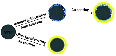
Almost two decades have passed since the first reports on the synthesis of Au@MNPs,31,32 but challenges still remain in different aspects of working with this category of nanoparticle. The first challenge is how to efficiently prepare highly monodisperse iron or iron oxide nanocrystals. This requires the nanoparticles to be made with precise control of particle size and magnetic properties. The greater challenge is how to effectively coat the core with a smooth, complete and tuneable gold shell. The most common methods are to coat magnetic nanoparticles by directly depositing gold onto the core surface or by using a chelating material between the core and gold shell.
The properties of Au@MNPs make overcoming these challenges worthwhile and the last few years have seen considerably progress in the synthesis and application of Au@MNPs. In this review, synthetic procedures, surface modification, and the analytical and biomedical applications of Au@MNPs are discussed. The first part focuses on the synthetic routes of iron oxide nanocrystals and the formation of the gold shell obtained either by direct deposition, or by using an initial ‘glue material’ on the magnetic cores. Following this, the functionalization of the Au@MNPs surface is presented. The next section discusses the analytical and biomedical applications of Au@MNPs, followed by a discussion on the cytotoxicity of these particles.
2. Synthesis of Au@MNPs
The synthesis of Au@MNPs involves two key processes, the iron or iron oxide core synthesis and the subsequent gold coating. In this section we will review the key solution techniques that have been developed in the preparation of magnetic cores followed by discussion of the main procedures to gold coat the magnetic cores.2.1. Synthesis of magnetic nanoparticles
The current synthetic routes for fabricating MNPs have become intensively investigated and they can be prepared by thermal decomposition, co-precipitation, micro-emulsion, and solvothermal/hydrothermal synthesis.33–35 A major chemical challenge involved in the synthesis of iron and iron oxide nanoparticles is defining reproducible experimental conditions that will produce nanoparticles with narrow size distribution for the desired size and that present good magnetic properties.The thermal decomposition methods of organometallic compounds and metal–surfactant complexes are commonly used in the synthesis of iron based nanoparticles due to the method producing monodisperse and highly crystalline NPs.36–38 A principle example of this technique is in the formation of iron nanoparticles by Peng et al. (Fig. 1a) which utilizes iron pentacarbonyl and oleylamine as precursor and capping agent respectively to produce particles with a diameter less than 10 nm and a narrow size distribution.37 In this one-pot reaction, a crystalline Fe3O4 shell is formed around the metallic cores upon exposure to air, offering a robust protection and dispersion stability to the nanoparticles.37 Although the thermal decomposition method is favourable due to excellent control of size and nanoparticle morphology, high and scaleable yield, the drawback is that the subsequent particles are only dispersible in organic solvents, and additional surface modification is required to allow for solubility in an aqueous phase for bio-applications.36,37,39–41
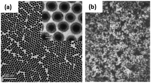 | ||
| Fig. 1 (a) TEM image of 4 nm/2.5 nm Fe/Fe3O4 nanoparticles synthesised via the thermal decomposition of iron pentacarbonyl. Inset: High resolution TEM image of the Fe/Fe3O4 nanoparticles; (b) SEM image of Fe3O4 nanoparticles synthesized via the co-precipitation method using iron(II) sulphate. ((a) Reprinted with permission from ref. 37 Copyright 2006, American Chemical Society. (b) Reprinted with permission from ref. 44 Copyright 1980, Elsevier Ltd.) | ||
An alternative synthesis which forms iron oxide nanoparticles in an aqueous phase is co-precipitation, whereby nanoparticles are either precipitated from a basic aqueous solution of ferric and ferrous salts,42 or ferrous hydroxide suspensions are partially oxidised using oxidising agents.43 A pioneering example implementing this method was performed by Sugimoto et al. using iron(II) sulphate (FeSO4) and potassium hydroxide (KOH) in the presence of nitrate ions (this being the oxidant), the resulting particles are presented in Fig. 1b.44 This method has opened the pathway to produce iron oxide nanoparticles in a robust manner with strong magnetic abilities. One advantage of this method is the capability to produce large quantities of magnetic nanoparticles in a short time. Additionally, it is possible to obtain nanoparticles with different sizes and shapes by adjusting the pH, ionic strength and concentration of growth solution. One challenge of the co-precipitation method is that the produced MNPs tend to agglomerate in aqueous and physiological environment. Our group has developed a solution to this challenge by immobilizing a positively charged polymer, polyethylenimine, onto particles surface during the synthesis.22,45 The polymer not only prevents particles aggregation but also allowed the anchoring of gold seeds for subsequent gold shell growth.
A third technique is the use of a microemulsion.46 This technique has been widely employed to synthesize MNPs because it yields nanoparticles within a narrow size distribution and it is possible to obtain spherical and cubic particles.14 There are two different approaches, one is the water-in-oil microemulsion, and the other is oil-in-water microemulsion. A successful example implementing this technique to synthesize iron MNPs has been achieved by Guo et al. who used a system containing an iron dioctyl sulfosuccinate sodium salt complex, sodium borohydride (reducing agent), and trioctyl phosphine oxide (capping agent). The materials assembled into reverse micelles due to the addition of xylene, water, and pyridine, which allowed for the diffusion of molecules and the subsequent formation of nanoparticles.47 The microemulsion method is a good option to precisely control the size, monodispersity and shape of the MNPs although it is not as simple as say the co-precipitation method to implement.
Finally, sol–gel methods48,49 can be used to synthesize spherical magnetite particles with a narrow size distribution.50 The key advantage of sol–gel methods is the obtaining of nanoparticles with high purity and compositional homogeneity at moderate temperature and using simple laboratory equipments. A drawback of this method is the toxic reagents which are often employed, for example propylene oxide.51
2.2. Gold coating
Gold shell can be formed directly or indirectly onto the magnetic core. In the direct methods the Au shell is formed directly on the core surface (Fig. 2). While in the indirect methods, a “glue material” is used between core and Au shell.The attachment of gold atoms to make a shell using the sodium citrate reduction of gold chloride is one of the simplest and most used methods. In this procedure, the Au layer is prepared by mixing the magnetic nanoparticles with boiling gold chloride aqueous solution, and under vigorous stirring the sodium citrate solution is introduced.27,52–54 In addition to acting as the reducing agent, sodium citrate also provides a citrate surface capping to the final Au@MNPs, which maintains nanoparticle stability and prevents aggregation. The formation of the Au shell is indicated by a solution colour change from brownish to burgundy.55–58 Using the hot citrate reduction technique, it is possible to obtain particles with a thin gold shell that are well dispersed and stable in water in a short reaction time. However, if the experimental conditions such as the MNPs/gold precursor ratio and concentration of reducing agent are not precisely selected, separated gold nanoparticles may be produced rather than forming a shell due to the high temperature reaction. Another drawback related to this method is that if the reaction solution is not under vigorous stirring, then agglomerates of MNPs might be coated instead of single MNP cores.
When the magnetic core nanoparticles are made in an organic phase they often have an oleic acid and oleylamine surface capping agent.59,60 The gold shell can either be formed onto the capping agent, or this ligand is removed from the MNP surface and the shell is formed directly onto the cores. In work reported by Sun and co-workers, a gold shell is formed on iron oxide nanoparticle coated with oleic acid and oleylamine by reduction of gold chloride in a chloroform solution containing oleylamine at room temperature.60 The oleylamine has two roles, firstly as mild reducing agent and secondly as a capping agent. The synthesized Au@MNPs are dispersed in a non-polar solvent, and with the aim of obtaining a thicker gold shell, the Au@MNPs were transferred to water by mixing them with sodium citrate and cetyltrimethylammonium bromide. After which, gold chloride was reduced using ascorbic acid in the presence of cetyltrimethylammonium bromide in order to increase the shell thickness.60 This method resulted in fully gold coated particles with a good control of gold shell thicknesses and smoothness.
In a different procedure reported by Wang et al., gold acetate was used as precursor and oleylamine as reducing agent.59 The initial iron oxide seeds had a surface capping consisting of both oleic acid and oleylamine, and were dispersed in phenyl ether. The gold acetate was reduced at elevated temperature (∼190 °C), which leads to a thermally activated desorption of the capping agent (oleic acid and oleylamine) from the iron oxide cores (Fig. 3), allowing the gold shell to form directly onto the iron oxide nanoparticle surface.59 Once the Au@MNPs have been produced, the particles are then re-encapsulated by the same capping agents. The advantage of this method is the production of gold shell with controllable surface capping properties (thermally activated desorption and adsorption of the capping layer). The final product is a mixture of fully coated Au@MNPs, partially gold coated and uncoated MNPs which could be separated using centrifugation to obtain the Au@MNPs from MNPs.
The reverse micelle method is also commonly used to form gold shells directly onto magnetic core. In most cases cetyltrimethylammonium bromide, octane and 1-butanol are used as surfactant, oil phase and co-surfactant, respectively.61–65 In these methods gold chloride is used as a precursor and sodium borohydride as a reducing agent.64 Cho et al. showed that the gold shell obtained using this technique grows by nucleating from small particles at selected sites on the magnetic core surface before developing the shell structure.66 The gold chloride is reduced to Au, which initiates a nanoscaled seed Au nanoparticles forming on the magnetic cores. Following this, the small colloidal particles of Au attached to the core template the growth of an Au overlayer. The thickness of the shell can be tuned by using different amounts of the gold precursor.66 The reverse micelle procedure is a good alternative to obtain tuneable gold shells, however there are several washing steps involved and stabilizing treatments may be required.
Gao and co-workers developed the use of poly-L-histidine as the glue material.68 The iron oxide nanoparticles used in this work had an oleic acid capping and were dispersed in chloroform. To enable the nanoparticles to become water dispersible, they were modified the surface with an amphiphilic polymer, phospholipid–polyethylene glycol terminated with a carboxylic acid. The pol-L-histidine was then adsorbed onto the amphiphilic polymer via electrostatic interactions. During the final step, gold chloride is reduced onto the chelating agent with hydroxylamine forming the gold shell. One advantage of this method is the formation of a gap between the core and the shell due to the oleic acid, phospholipid and polypeptide capping. As a result of the gap, thin and smooth gold nanoshells form on the polypeptide rather than directly on core nanoparticles surface, resulting in monodisperse Au@MNPs (Fig. 4). Another advantage is that the gold shell thickness can be readily tuned by changing the amount of gold ions.68 The synthesis does involve many washing steps, which may cause loss of particles during the process.
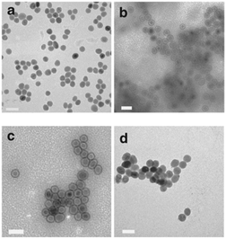 | ||
| Fig. 4 TEM imaging of the Au@MNPs. TEM images (a) MNPs, and (b–d) Au@MNPs with various shell thickness (b, ∼1 to 2 nm; c, 2–3 nm; d, 4–5 nm). Scale bars are 50 nm. (Reprinted by permission from Macmillan Publishers Ltd: Nature Communications, ref. 68, copyright 2010.) | ||
In a study by Hu et al., a cross-linked polymer poly(cyclotriphosphazene-co-4,4′-sulfonyldiphenol) (PZS) was used as the glue material.67 The PZS layer was formed onto the magnetic cores (which were synthesized by heating salts in polyalcohols) by polymerization of hexachloro-cyclotriphosphazene and 4,4′-sulfonyldiphenol. Next, gold seeds were adsorbed on the PZS by reduction of HAuCl4 by NaBH4. Subsequently, the seed-mediated growth of the Au nanoshell was achieved via hot reduction of HAuCl4 using sodium citrate as reducing agent.67 PZS is a good candidate as a glue material due to its strong metal coordination capability. In addition, the PZS shell thickness can be tuned by varying the mass ratio of the magnetic cores to the PZS precursors.67 The PZS coats agglomerates of MNPs rather single particles, which may produce polydisperse Au@MNPs. Additionally, although a gold seeded-mediated growth of gold was used, the final Au@MNPs obtained using this method are not fully coated with gold, leaving PZS exposed areas.
Goon et al. reported the use of the polymer polyethyleneimine as a glue layer.22,69,70 The positively charged polymer was immobilized onto the negatively charged iron oxide nanoparticles obtained using Sugimoto's method44 by electrostatic interactions. The polymer allowed the controlled attachment of negatively charged Au nanoparticles seeds. The polymer coating is then repeated with the seeded-polymer-iron oxide nanoparticles; and finally the gold shell was grown around the nanoparticles by iterative reduction of gold chloride using hydroxylamine as a reducing agent. The advantage of this procedure is that a thick gold shell is obtained, guaranteeing the Au@MNPs inherent electrical conductivity and chemical stability. However, as result of the iterative gold reduction rather polydispersed Au@MNPs are obtained.
Silica has been successfully used in core–shell nanoparticles synthesis.71,72 Diaz and co-workers reported the formation of a gold shell on silica and a combination of three polyelectrolytes as glue layer.73 Firstly, the magnetic cores, which were obtained by co-precipitation, were coated with a silica shell through the sol–gel process based on the hydrolysis of tetraethyl orthosilicate. Secondly, three layers of positively charged polyelectrolytes were formed on the silica-magnetic nanoparticles, ensuring the nanoparticles a smoother and more uniform surface. The gold shell was formed by molecular self-assembly of negative charged Au seeds and subsequent colloidal Au growth using HAuCl4 and ascorbic acid as the reducing agent. The final gold shell produced by this process was 30 nm thick.73 This work yielded particles with a complete gold coating and a tunable plasmon resonance in the visible-near-infrared range. One drawback with this method is the low saturation magnetization of the Au@MNPs as result of the diamagnetic contribution of the thick silica shell surrounding the magnetic cores.
Another challenge is to characterize the Au@MNPs morphologically. As the particles are magnetic at room temperature, they tend to aggregate during the drying stages of sample preparation. Due to this aggregation the images obtained by techniques such as transmission and scanning electron microscopy can be unclear.
3. Surface modification of Au@MNPs
So why is the surface modification of Au@MNPs so important for their use in analytical chemistry and biomedicine? The ability to modify the nanoparticles surface in a controllable manner on a molecular level is necessary to impart specificity, sensitivity and biological compatibility to Au@MNPs. An example of the importance of this is in the development of biosensors where the Au@MNPs can be used as active elements. A biosensor is comprised of a signal transducer with an immobilized biological molecule, which gives the biosensor selectivity to the target analyte, and the transducer measures the extent of the reaction between biorecognition molecule and analyte.74 Functional molecules often do not bind selectively with gold and hence require linkers, which serve as bridges for the attachment of the functional molecules to the Au@MNPs. The molecular level modification of gold based nanomaterials by using self-assembled monolayers (SAMs) or complex molecular assemblies have been considerably investigated since the work firstly reported by Nuzzo and Whitesides on the formation of SAMs on planar gold.75 A variety of functional molecular linkers can be employed to modify the surface of nanoparticles such as aryl diazonium salts76 and alkanethiols.77 Wang et al., demonstrated the ability to control the surface and interparticle spatial properties of Au@MNPs by modifying them with 1,9-nonanedithiol and mercaptoundecanoic acid.78 They explored the ligand-exchange reactivity at the gold shell surface and formed a thin film assembly of the Au@MNPs. Initially, the Au@MNPs had an oleylamine capping, which was replaced by a thiolate–oleylamine exchange reaction. This was proceed by cross-linking, either via alkyl chains when using dithiols as a linker, or via hydrogen bonding if using a carboxylic acid functionalized thiol as a linker, as illustrated in Fig. 5.78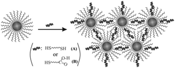 | ||
| Fig. 5 Illustration of the thiolate–oleylamine exchange reaction followed by cross-linking via different linkers (A and B) for the assembly of Au@MNPs. (Reproduced from ref. 78 with permission from The Royal Society of Chemistry.) | ||
The functionalization of Au@MNPs is also important for preventing adsorption of fouling species. This is particularly critical for biological applications where the Au@MNPs will be placed in complex matrices, the Au@MNPs must ideally resist surface fouling and/or signal interfering molecules which can influence the analytical performance.16,74,77 Additionally, as the Au@MNPs can aggregate due to attractive magnetic forces between nanoparticles; the surface modification is crucial to enhance nanoparticle stability by affecting the electrostatic charge on their surface. Previously it has been shown in our group that SAMs formed by molecules such as 3-mercaptopropionic acid and thiocholine on Au@MNPs can reduce the aggregation process of nanoparticles. In this study, these thiolated compounds have also shown to be effective for tailoring the nanoparticle surface charge as a result of the interactions of the different functional moieties with H+ and OH−.79
4. Applications
Au@MNPs have potential in many applications ranging from electrochemical biosensing, to medical imaging and therapies. The following section will review some of the more prominent research.4.1. Au@MNPs incorporated electrochemical sensors
Due to the conductivity of gold, the growth of an Au shell around a magnetic core provides a practical approach for the electrochemical addressability of magnetic nanoparticles. Different strategies have been applied for integrating Au@MNPs into electrochemical sensors, which are categorized in the following sub-sections.As an example, Pham and Sim presented an electrochemical impedance immunosensor for detecting the interaction between human immunoglobulin (IgG) and protein A from Staphylococcus aureus based on the immobilization of human IgG on the surface of Au@MNPs.81 To immobilize human IgG onto the Au@MNPs, Au@MNPs were modified with a self-assembled monolayer of 11-mercaptoundecanoic acid. This was followed by attaching modified Au@MNPs to the surface of a modified magnetic carbon paste electrode using a magnetic force. The surface was dried, washed with PBS to remove any unbound nanoparticles before being incubated with protein A and before the electrochemical measurement. This immunosensor was able to detect the minimum concentration of the target analyte as low as 20 nM.81
In another study by Yang and colleagues, a H2O2 biosensor based on Au@MNPs was developed.82 Here, Au@MNPs coated with Horseradish peroxidase were adsorbed on a printed electrode modified with graphene sheets-Nafion using an external magnetic field. This electrochemical biosensor showed a detection limit of 12 mM to H2O2. Pundir and colleagues also reported two separate biosensors based on an Au@MNPs modified electrode for detecting sulphite24 and glutathione.80 To detect sulfite, sulfite oxidase was immobilized onto carboxylated Au@MNPs. This was followed by electrodeposition of Au@MNPs onto the surface of a gold electrode through N-ethyl-N′-(3-dimethylaminopropyl)carbodiimide and N-hydroxysuccinimide chemistry. To detect glutathione, using a similar principle, chitosan was immobilized onto the surface of Au@MNPs to introduce amino groups. Next, electrodeposition of Au@MNPs onto the surface of a Pt electrode was followed by covalent attachment of glutathione oxidase onto the surface of Au@MNPs modified Pt electrode. The sulfite and glutathione biosensor presented a detection limit of 0.15 μM and 0.1 μM, respectively.
Despite the sensitivity of these approaches for their target analyte, the detection limit achieved by these methods is limited to a range between mM to nM. Having a fixed position for the sensing interface leads to limited sensitivity of these strategies due to the mass transfer limitation at low analyte concentration. This is basically because the flux of material that will be brought to the sensing surface depends on the rate of diffusion, and the time taken for a species to diffuse through a volume has a squared dependency on the thickness of that volume. Hence for a 1 fM solution, even diffusing to 1 nm spacing from a 50 nL solution, the time to detect all molecules in that volume would be approximately 10 hours.83
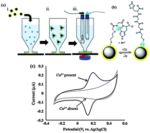 | ||
| Fig. 6 (a) Outline of the steps required for the measurement of a target analyte, (i) dispersion of Fe3O4–Aucoat into sample; (ii) analytes bind selectively to Fe3O4–Aucoat; (iii) captured analyte is attracted to a transducing electrode for quantification. (b) The Cu2+/Cu0 redox reaction occurring for Cu2+ complexed with GlyGlyHis. (c) Characteristic cyclic voltammograms of nanoelectrodes performed in the absence and presence of Cu2+. (Reproduced from ref. 84 with permission from The Royal Society of Chemistry.) | ||
The concept of dispersible electrodes was first tested for the detection of Cu2+ by employing the tri-peptide ligand glycine-glycine-histidine (GlyGlyHis) (Fig. 6c).84 A detection limit of 2 pM (0.13 ppt) was achieved, which represents a more than 1000-fold decrease in the lowest detection limit relative to a planar GlyGlyHis modified gold electrode. The reason the detection limit is significantly lower than the planar electrodes for the same affinity ligand is because virtually all the analyte is collected and detected. This was demonstrated by inductively coupled plasma mass spectrometry (ICP-MS) where the amount of Cu2+ left in a 1 ppb solution after incubation in Au@MNPs-GGH nanoparticles was below the 0.1 ppb detection limit of the ICP-MS. The Au@MNPs current response was reported to reach a stable value after approximately 5 minutes incubation. In contrast, for planar electrodes incubated in 50 nM Cu2+ (50 times higher than for the Au@MNPs-GGH nanoparticles), the current response was still increasing after 20 minutes.
The application of dispersible electrodes for the detection of prostate-specific antigen (PSA), as a non-electroactive species, was also explored.69 The lowest detected PSA concentration was found to be 100 fg mL−1, which is three orders of magnitude lower than the pg mL−1 detection limits for planar electrodes. The incubation time required to achieve a steady response for 5 pg mL−1 of PSA was reported only 1 hour as compared with 4 hours for the assay required for the flat surfaces.
Following these studies, and based on a similar concept, Rodriguez and colleagues also reported an Au@MNPs based disposable magnetic biosensor for detection of DNA hybridization.85 An enzymatic amplification approach was utilized for the detection of hybridization in this case. To do this, a thiolated 19-mer capture probe was attached to Au@MNPs and hybridized with a biotinylated target followed by attachment of streptavidin peroxidase to the biotinylated target. The resulting modified Au@MNPs were collected using a magnetic field on the surface of carbon screen printed electrodes, where electrochemical measurements were performed using hydroquinone as mediator. A detection limit of 31 pM for target DNA has been reported using this method.
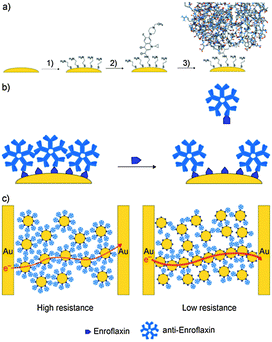 | ||
| Fig. 7 The biochemiresistor concept. (a) Functionalization of Au@MNPs (yellow) with a self-assembled monolayer of cysteamine (step 1) followed by the attachment of enrofloxacin (2). The surface-bound enrofloxacin serves as selective binding sites for anti-enrofloxacin IgM antibodies Ab–Au@MNPs (3). (b) The Ab–Au@MNPs are the biosensing particles. When distributed into a sample solution that contains enrofloxacin, some of the anti-enrofloxacin dissociates from the Ab–Au@MNPs to bind with the enrofloxacin in solution. (c) Ab–Au@MNPs magnetically assembled between two interdigitated electrodes. Such films have high resistance. After exposure to the solution sample, and dissociation of antibodies, some particles in the nanoparticle film can approach each other more closely, and the resistance of the film decreases. The greater the amount of analyte, the more antibodies are displaced from the surface of the Au@MNPs, and the lower the resistance. (Reproduced from ref. 88 Copyright 2010, with permission from WILEY-VCH Verlag GmbH & Co. KGaA, Weinheim.) | ||
4.2. Au@MNPs incorporated optical sensors
The growth of an Au shell around a magnetic nanoparticle provides a plasmon resonant optical response. The resonant frequency is determined by geometry, dielectric properties of the nanoparticle core, and surrounding medium of the nanoparticle.89Optical addressability of Au@MNPs has recently started to be explored using techniques such as plasmonic and surface enhanced Raman spectroscopy.90
An increase in the thickness of the Au shell has been shown to cause a shift in the position of the plasmon peak to longer wavelengths, which is attributed to the large dielectric permittivity of the core (Fig. 8). In this study, the effects of the various core shapes fabricated on the plasmonic properties of Wüstite Au@MNPs was also investigated using the finite-difference time-domain method.91 The dipolar resonances for the nanoparticles with cubic and concave cubic cores were found slightly red-shifted compared to nanoshells with a spherical core. For a cubic core, and more strongly for a concave cubic core, an additional quadrupolar plasmon resonance was observed. The differences in the optical properties of Au@MNPs introduced by a nonspherical core were attributed to the reduction of symmetry introduced by the variations in core geometries. This study clearly highlighted the potential of varying the Au shell thickness as well as core shape for tuning the plasmonic properties of Au@MNPs.60,91 Since Au@MNPs nanostructures can assemble under an applied magnetic field, assembly of the Au@MNPs into arrays could be utilized for the development of photonic–magnetic nanodevices in future. Analytical applications involving the optical properties of these materials are just beginning to emerge.
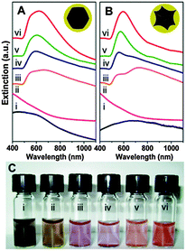 | ||
| Fig. 8 Solution extinction measurements of (A) faceted (B) and Au@MNPs (i) ethanolic uncoated cores (r1 31.5 ± 9.7 and 28.5 ± 7.3 nm), (ii) Au decorated precursor nanoparticles (r1 32.6 ± 9.0 and 28.6 ± 8.5 nm) in aqueous solution, and (iii–vi) Au coated nanoparticles with increasing Au thicknesses number of particles sized is 100, r2 is 59.9 ± 12.4, 65.0 ± 19.9, 73.1 ± 11.7, and 76.6 ± 9.8 nm for the faceted cores and 40.0 ± 6.7, 49.1 ± 10.7, 53.8 ± 4.6, and 66.4 ± 5.0 nm for the tetracubic cores in aqueous solution. (Spectra offset for clarity.) (C) Optical image of particles shown in A. (Reprinted with permission from ref. 91 Copyright 2009, American Chemical Society.) | ||
Pereira and co-workers reported the SERS performance of star shaped Au@MNPs for the detection of Astra Blue, a Cu phthalocyanine derivative and IR Raman probe.93 The detection limit of Astra Blue was found to be 0.01 mM in solution. To improve the detection signal, Au@MNPs were concentrated by means of a strong permanent magnet. Strong signals were only collected from regions with aggregated nanoparticles, whereas nearly no contribution to the SERS signal is observed from areas between nanoparticles arrays. The observation of the controlled creation of hot-spots induced by magnetic forces presents an interesting application for SERS biodetection using Au@MNPs.
In another study using Au@MNPs,94 the ability to control the formation of stable small clustering sizes of Au@MNPs was shown to enhance SERS intensities for samples in solution as compared with samples on solid substrates. This observation is attributed to the inter-particle distance dependence of ‘hot-spot’ SERS sites.
4.3. Bio-separation
Au@MNPs have been shown to be useful for separating proteins simply with the assistance of an external magnetic field, while preserving the catalytic activity of the protein after being separated.In a study performed by Lim and co-workers,94 decanethiol capped Au@MNPs were first converted to water-soluble particles by a ligand exchange reaction with 11-mercaptoundecanoic acid. The 11-mercaptoundecanoic acid-capped Au@MNPs in water underwent a further exchange reaction with a protein-coupling agent, dithiobis (succinimidyl propionate) to which antibodies were then immobilized onto the resulting nanoparticles. The anti-rabbit IgG-immobilized Au@MNPs were then reacted with Au nanoparticles capped with both protein A and a Raman label for SERS analysis. Results from control experiments were included for comparison, in which the Au particles capped with bovine serum albumin were used to replace the Au nanoparticles capped with protein A while maintaining the rest of the conditions. The specific reactivity between Au@MNPs capped with anti-rabbit IgG and Au nanoparticles capped with protein A was shown by a gradual decrease of the surface plasmon resonance band and its expansion in the longer-wavelength region. This finding was in contrast to the lack of any change in the surface plasmon band for the reaction between Au@MNPs capped with anti-rabbit IgG and Au nanoparticles capped with bovine serum albumin. Comparing the results of this method with those from a Bradford protein assay and sodium dodecyl sulfate-polyacrylamide gel electrophoresis, suggested that immobilization of proteins on Au@MNPs and the subsequent recognition of the targeted proteins provides a better means for the separation of proteins via application of a magnetic field. This suggests the viability of exploiting the Au@MNPs for magnetic bioseparation.
The selective capture of histidine-tagged maltose-binding protein from a crude cell extract is also reported using star-shaped Au@MNPs.93 Recovery of the protein by this method was assessed by sodium dodecyl sulfate polyacrylamide gel electrophoresis with Coomassie blue staining. No protein was detected in the intermediate washings with buffer or in the control sample magnetically separated with non-functionalized Au@MNPs, confirming the specificity of the method.
Considering the versatility of the surface modification of gold, Au@MNPs clearly have shown the potential for being used in concentrating a specific analyte from dilute solutions, simply using a magnet placed at the bottom of the container and removing the required volume of excess solvent at the top, allowing for the capture and detection of trace biomolecules.
4.4. Biomedical applications
MNPs have been used in the clinical environment for many years due to their good magnetic resonance imaging (MRI) properties and biocompatibility. Recently, interest has grown in combining Au@MNPs nanoparticles with other non-toxic materials to allow for one agent to be utilised in several applications. Here, the importance of Au@MNPs in three of the major clinical fields will be discussed.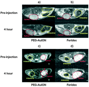 | ||
| Fig. 9 In vivo MR imaging of tumors. (a and b) T2-weighted images of subcutaneous C26 murine carcinoma (tumor sites are circled by red line) at 4 h after intravenous injection of PEG–Au@MNPs (a) and Feridex (b). (c and d) T2-weighted images of an orthotopic MiaPaCa-2 human pancreatic cancer model (tumor sites are circled by red line) at 4 h after intravenous injection of PEG–Au@MNPs (c) and Feridex (d). (Reprinted with permission from ref. 28 Copyright 2010, WILEY-VCH Verlag GmbH & Co. KGaA, Weinheim.) | ||
Other research in this field concentrates on the combination of various modalities allowing for both anatomical and physiological information to be obtained simultaneously about a region of interest. This not only reduces the overall scanning time, but also allows for more accurate superimposition of images due to the lack of temporal changes and other factors such as the involuntary movement of internal organs.100 Magnetic resonance-computed tomography, magnetic resonance-ultrasound imaging, and magnetic resonance-photoacoustic imaging are three such combinations requiring magnetic and plasmonic imaging probes.
As previously mentioned, MRI involves the use of a magnetic field, computed tomography however relies on the attenuation of X-rays.98 A combination of these modalities allows for the acquisition of anatomical information of soft and hard tissues simultaneously, generating images with high resolution, hence providing more detailed biological information.101 A third technique yielding functional information is ultrasound imaging, whereby an area is flooded by sound waves producing an echo through which molecular data is obtained.102 Carril et al. designed a MRI- computed tomography-ultrasound imaging trimodal imaging probe based on 6.1 nm Au@MNPs with a sugar-coating. The study revealed that the gold coating enhances computed tomography contrast when irradiated with X-rays in comparison to bare iron oxide cores. The Au@MNPs were also suitable for T2-weighted MR imaging and allowed for the possibility of imaging extravascular regions using ultrasound, which is not achievable with the microbubbles currently in clinical use.103
A further technique is photoacoustic imaging where contrast is dependent on the absorption of light, and particular cellular mechanisms can be studied with the aid of contrast agents.104 Ma et al. formulated Au@MNPs with nanoroses shape.105 The synthesised structures were found to possess a high r2 relaxivity of 219 mM−1 s−1 resulting in a significant increase in the darkening of images in comparison to Feridex. Furthermore, in vitro cell experiments (Fig. 10) revealed enhanced near-infrared absorbance with an increasing concentration of nanoparticles, suggesting the applicability of these particles in photoacoustic imaging.105 The thin gold coating and the porosity of the Au@MNPs assisted high near-infrared absorbance as a result of collective responses of the electrons and reduced symmetry of the interactions between plasmon modes.105
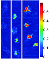 | ||
| Fig. 10 Hyperspectral microscopy images illustrating strong absorbance at 755 nm for nanorose in macrophages in vitro. The legend provides a color code for the optical density values up to 0.6. From left to right, macrophages were incubated with nanoroses (0.0, 1.0, and 10 μg Au per mL media) for 24 h. (Reprinted with permission from ref. 105 Copyright 2009, American Chemical Society.) | ||
The above cases demonstrate the potential of these materials to be used as a diagnostic tool, however using these nanoparticles as a therapeutic agent simultaneously has added benefits to patients. The next section describes how Au@MNPs have the capacity to aid in the treatment of disease, such as carcinoma.
Several studies have been conducted in recent years exploiting the multiple functionality of hybrid nanomaterials. For example, Hoskins et al. demonstrated the in vitro effectiveness of Au@MNPs as hyperthermia agents in a study focused on A375M human melanoma cells.107 Experiments using agar were performed whereby Au@MNPs were irradiated with a 532 nm laser, resulting in a temperature increase of 32 °C which was restricted to the accumulation site. The investigation also emphasised the considerations needed regarding temperature recovery time of cells and nanoparticle dosage amounts.107 A further study supporting these findings was performed by Sotiriou et al. who developed nanoaggregates consisting of SiO2-coated Fe2O3 and Au nanoparticles resulting in a nanoprobe with MR imaging, magnetic targeting, and photothermal capabilities, Fig. 11.108 The superparamagnetism of the hybrid nanoparticles facilitated the placement and manipulation of the probes, while the Au when irradiated at an appropriate wavelength, allowed the conversion of light into heat killing the cancer cells. The tumour ablation ability of these particles was examined in vitro using a human breast cancer cell line (MDA-MB-231), revealing a temperature increase of approximately 50 °C subsequently killing all cells present, see Fig. 11b.108
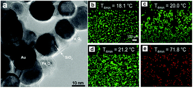 | ||
| Fig. 11 (a) High-resolution TEM image of Au@MNPs coated with 2.6 nm-thick amorphous SiO2 shells (5.7 wt% SiO2); fluorescent images of breast cancer cells on glass slides stained with LIVE/DEAD dye (green = live, red = dead). (b) Cells alone, (c) cells incubated with 20 mg L−1 Au@MNPs without any laser irradiation, (d) cells alone irradiated with a laser, and (e) cells incubated with particles (20 mg L−1) and irradiated with a laser. The irradiation was applied at a flux (power per area) of 4.9 W cm−1 for 4 min. The increase in temperature ΔT max of the glass slides after 4 min of laser irradiation is also shown. Only in the presence of particles are the cells killed by the laser. The scale bars are identical in all images. (Reprinted with permission from ref. 108 Copyright 2014, WILEY-VCH Verlag GmbH & Co. KGaA, Weinheim.) | ||
The future of hyperthermic materials for use as a remedy will most likely be in combination with currently available therapeutic treatments, such as chemotherapy and radiotherapy. The following section will outline studies assessing this hypothesis.
A second attractive target which may benefit from combined chemo-photothermal therapy is rheumatoid arthritis. Current methods of treating this inflammatory disease are primarily based on disease-modifying anti-rheumatic drugs,110 however there are associated side effects, including liver toxicity, that occur as a result of long term use.111 Currently, the most widely available disease-modifying anti-rheumatic drugs is methotrexate and one research area is in developing new drug delivery systems to allow for administration of overall small dosages but with localised high methotrexate concentration in affected areas.112 One such strategy has been designed by Kim et al.,112 and uses poly(lactic-co-glycolic acid) to encapsulate methotrexate resulting in polyethylene glycol coated nanoparticles with a drug loading of 2.5 wt%.113
Gold–iron–gold half nanoshells were subsequently deposited on these particles, after which RGD peptides were conjugated, to encourage the particles to adhere to cells, resulting in magnetic- and bio-targeted plasmonically active nanoparticles.112 Collagen-induced arthritic mice displaying an arthritis index of 8–10 were treated with the synthesised particles, near-infra red irradiation, and magnetic targeting revealed an accelerating drug release rate resulting in a near 50% decrease in the index value, as demonstrated in Fig. 12. This investigation displays how a lower dose of drug-loaded Au@MNPs can be used to improve the therapeutic response in comparison to current clinical approaches.112
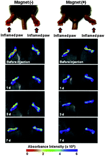 | ||
| Fig. 12 Time-lapse in vivo NIR absorbance images of inflamed paws of CIA mice injected intravenously with Au@MNPs (150 mL, 1 mg mL−1 in PBS) and caged with (+) or without (−) a magnet. (Reprinted with permission from ref. 112 Copyright 2015, Elsevier Ltd.) | ||
The above sections demonstrate suitability of Au@MNPs for use in the clinical environment. The versatility of these materials allows for the acquisition of anatomical and functional information, alongside further functionalization to allow for specific targeting and drug delivery.
5. Cytotoxicity
The basic criteria for clinical application of nanomaterials are safety and good biocompatibility. Having a low cytotoxicity, is critically important for Au@MNPs to be used in vivo. While a considerable number of studies have been done on the synthesis and coating process of Au@MNPs, attention devoted to the biocompatibility for in vivo biomedical applications to ensure their safe clinical use of is still limited.Chao and co-workers demonstrated that Au@MNPs are capable of loading and releasing the anticancer drug doxorubicin (Dox) as well as its targeting to tumor site.114 The cytotoxicities of Au@MNPs and Au@MNPs loaded with Dox (Dox–Au@MNPs) combined with an external magnetic field were tested in vitro on HepG2 malignant tumor cells. The results showed that cell viability remained above 92% when using Au@MNPs at a concentration as high as 2.0 mg mL−1, suggesting good biocompatibility of the Au@MNPs. This is while super paramagnetic iron oxide nanoparticles have been found in tests to cause a 60% loss of cell viability at the concentration tested of 2.0 mg mL−1.115 This suggests that Au@MNPs have better biocompatibility and have lower cytotoxicity compared to iron oxide MNPs, probably due to the Au component. The IC50 (0.731 g mL−1) of the Dox–Au@MNPs group was higher than that (0.522 g mL−1) of the Dox group (P < 0.05). However, the Dox–Au@MNPs group combined with a magnetic field had an obviously increased inhibition rate for the HepG2 cell line and the IC50 was lower than that of the Dox group (0.421 g mL−1). These results indicated that Au@MNPs loaded with doxorubicin combined with a permanent magnetic field are more cytotoxic and could be a potential targeted drug delivery system.
6. Conclusions and future perspective
The application of Au@MNPs for analytical chemistry and biomedicine has seen some successful examples. These elegant examples are the outcomes of the progress made in synthesis and characterization of Au@MNPs with appropriate functional groups. From the perspective of electrochemical and optical sensing, the ability to use the Au@MNPs as active elements allows the concentration, separation and capture of analytes enhancing the analytical detection. By using Au@MNPs incorporated in electrochemical sensors it is possible to detect a number of analytes of biological and environmental interest. Over the last few years, besides using Au@MNPs in conventional configurations, new concepts of electrochemical sensors using Au@MNPs have been reported, including dispersible electrodes and the biochemiresistor. The ‘dispersible electrodes’ concept has shown excellent performance with extremely low detection limits towards different analytes, such as copper and prostate-specific antigen. The ability of varying the Au shell thickness as well as core shape during the synthesis allows the tuning of the plasmonic properties of Au@MNPs making possible the development of optical sensors.So where will research using Au@MNPs for different applications go in the future? It gives the impression likely their popularity will only grow. What has been achieved so far in the synthesis of Au@MNPs clearly demonstrates that novel sensing concepts and other nano-devices will certainly play a dominant role in the future. However, there is still considerable work to be performed in terms of optimizing the synthetic routes to obtain better and robust Au@MNPs. With regards to using Au@MNPs in biomedical applications, Au@MNPs presents enormous potential to be used as a diagnostic and therapeutic tool. However, to date most research stands on proof-of-concept stage and detailed preclinical studies need to be undertaken.
Acknowledgements
The authors acknowledge the generous financial support from the Australian Research Council Centre of Excellence in Convergent Bio-Nano Science and Technology (CE140100036) and an ARC Australian Laureate Fellowship to JJG (FL150100060). SMS is a scholarship student from CNPq, Conselho Nacional de Desenvolvimento Científico e Tecnológico and INCTBio, Instituto Nacional de Ciência e Tecnologia em Bioanalítica – Brazil.Notes and references
- J. S. Beveridge, J. R. Stephens and M. E. Williams, Annu. Rev. Anal. Chem., 2011, 4, 251–273 CrossRef CAS PubMed.
- P. C. Lin, P. H. Chou, S. H. Chen, H. K. Liao, K. Y. Wang, Y. J. Chen and C. C. Lin, Small, 2006, 2, 485–489 CrossRef CAS PubMed.
- A. H. Latham, R. S. Freitas, P. Schiffer and M. E. Williams, Anal. Chem., 2005, 77, 5055–5062 CrossRef CAS PubMed.
- J. C. Liu, P. J. Tsai, Y. C. Lee and Y. C. Chen, Anal. Chem., 2008, 80, 5425–5432 CrossRef CAS PubMed.
- P. H. Chou, S. H. Chen, H. K. Liao, P. C. Lin, G. R. Her, A. C. Y. Lai, J. H. Chen, C. C. Lin and Y. J. Chen, Anal. Chem., 2005, 77, 5990–5997 CrossRef CAS PubMed.
- R. Hirsch, E. Katz and I. Willner, J. Am. Chem. Soc., 2000, 122, 12053–12054 CrossRef CAS.
- H. Y. Tsai, C. F. Hsu, I. W. Chiu and C. B. Fuh, Anal. Chem., 2007, 79, 8416–8419 CrossRef CAS PubMed.
- L. Z. Gao, J. Zhuang, L. Nie, J. B. Zhang, Y. Zhang, N. Gu, T. H. Wang, J. Feng, D. L. Yang, S. Perrett and X. Yan, Nat. Nanotechnol., 2007, 2, 577–583 CrossRef CAS PubMed.
- Z. M. Liu, Y. L. Liu, H. F. Yang, Y. Yang, G. L. Shen and R. Q. Yu, Anal. Chim. Acta, 2005, 533, 3–9 CrossRef CAS.
- J. Wang, Z. G. Zhou, L. Wang, J. Wei, H. Yang, S. P. Yang and J. M. Zhao, RSC Adv., 2015, 5, 7349–7355 RSC.
- C. Sun, J. S. H. Lee and M. Q. Zhang, Adv. Drug Delivery Rev., 2008, 60, 1252–1265 CrossRef CAS PubMed.
- M. Liong, J. Lu, M. Kovochich, T. Xia, S. G. Ruehm, A. E. Nel, F. Tamanoi and J. I. Zink, ACS Nano, 2008, 2, 889–896 CrossRef CAS PubMed.
- J. H. Gao, H. W. Gu and B. Xu, Acc. Chem. Res., 2009, 42, 1097–1107 CrossRef CAS PubMed.
- A. K. Gupta and M. Gupta, Biomaterials, 2005, 26, 3995–4021 CrossRef CAS PubMed.
- K. C. de Souza, G. F. Andrade, I. Vasconcelos, I. M. D. Viana, C. Fernandes and E. M. B. de Sousa, Mater. Sci. Eng., C, 2014, 40, 275–280 CrossRef CAS PubMed.
- J. J. Gooding and S. Ciampi, Chem. Soc. Rev., 2011, 40, 2704–2718 RSC.
- S. H. Koenig and K. E. Kellar, Magn. Reson. Med., 1995, 34, 227–233 CrossRef CAS PubMed.
- D. Yang, X. C. Pang, Y. J. He, Y. Q. Wang, G. X. Chen, W. Z. Wang and Z. Q. Lin, Angew. Chem., Int. Ed., 2015, 54, 12091–12096 CrossRef CAS PubMed.
- Y. R. Cui, C. Hong, Y. L. Zhou, Y. Li, X. M. Gao and X. X. Zhang, Talanta, 2011, 85, 1246–1252 CrossRef CAS PubMed.
- H. Y. Park, M. J. Schadt, L. Wang, I. I. S. Lim, P. N. Njoki, S. H. Kim, M. Y. Jang, J. Luo and C. J. Zhong, Langmuir, 2007, 23, 9050–9056 CrossRef CAS PubMed.
- J. L. Lyon, D. A. Fleming, M. B. Stone, P. Schiffer and M. E. Williams, Nano Lett., 2004, 4, 719–723 CrossRef CAS.
- I. Y. Goon, L. M. H. Lai, M. Lim, P. Munroe, J. J. Gooding and R. Amal, Chem. Mater., 2009, 21, 673–681 CrossRef CAS.
- A. Ahmadi, H. Shirazi, N. Pourbagher, A. Akbarzadeh and K. Omidfar, Mol. Biol. Rep., 2014, 41, 1659–1668 CrossRef CAS PubMed.
- R. Rawal, S. Chawla and C. S. Pundir, Biosens. Bioelectron., 2012, 31, 144–150 CrossRef CAS PubMed.
- S. W. Wang, Y. Zhang, J. H. Yu, X. R. Song, S. G. Ge and M. Yan, Sens. Actuators, B, 2012, 171, 891–898 CrossRef.
- M. L. Yola, T. Eren and N. Atar, Electrochim. Acta, 2014, 125, 38–47 CrossRef CAS.
- T. Ahmad, H. Bae, I. Rhee, Y. Chang, S. U. Jin and S. Hong, J. Nanosci. Nanotechnol., 2012, 12, 5132–5137 CrossRef CAS PubMed.
- M. Kumagai, T. K. Sarma, H. Cabral, S. Kaida, M. Sekino, N. Herlambang, K. Osada, M. R. Kano, N. Nishiyama and K. Kataoka, Macromol. Rapid Commun., 2010, 31, 1521–1528 CrossRef CAS PubMed.
- S. Kayal and R. V. Ramanujan, J. Nanosci. Nanotechnol., 2010, 10, 5527–5539 CrossRef CAS PubMed.
- H. Salehizadeh, E. Hekmatian, M. Sadeghi and K. Kennedy, J. Nanobiotechnol., 2012, 10, 3 CrossRef CAS PubMed.
- E. E. Carpenter, C. Sangregorio and C. J. O'Connor, IEEE Trans. Magn., 1999, 35, 3496–3498 CrossRef CAS.
- E. E. Carpenter, J. A. Sims, J. A. Wienmann, W. L. Zhou and C. J. O'Connor, J. Appl. Phys., 2000, 87, 5615–5617 CrossRef CAS.
- S. Laurent, D. Forge, M. Port, A. Roch, C. Robic, L. V. Elst and R. N. Muller, Chem. Rev., 2008, 108, 2064–2110 CrossRef CAS PubMed.
- T. D. Schladt, K. Schneider, H. Schild and W. Tremel, Dalton Trans., 2011, 40, 6315–6343 RSC.
- K. Turcheniuk, A. V. Tarasevych, V. P. Kukhar, R. Boukherroub and S. Szunerits, Nanoscale, 2013, 5, 10729–10752 RSC.
- Z. Li, Q. Sun and M. Y. Gao, Angew. Chem., Int. Ed., 2005, 44, 123–126 CrossRef CAS PubMed.
- S. Peng, C. Wang, J. Xie and S. H. Sun, J. Am. Chem. Soc., 2006, 128, 10676–10677 CrossRef CAS PubMed.
- J. Park, J. Joo, S. G. Kwon, Y. Jang and T. Hyeon, Angew. Chem., Int. Ed., 2007, 46, 4630–4660 CrossRef CAS PubMed.
- D. S. Ling and T. Hyeon, Small, 2013, 9, 1450–1466 CrossRef CAS PubMed.
- P. H. L. Tran, T. T. D. Tran, T. V. Vo and B. J. Lee, Arch. Pharmacal Res., 2012, 35, 2045–2061 CrossRef CAS PubMed.
- W. W. Yu, J. C. Falkner, C. T. Yavuz and V. L. Colvin, Chem. Commun., 2004, 2306–2307 RSC.
- P. Majewski and B. Thierry, Crit. Rev. Solid State Mater. Sci., 2007, 32, 203–215 CrossRef CAS.
- P. Tartaj, M. D. Morales, S. Veintemillas-Verdaguer, T. Gonzalez-Carreno and C. J. Serna, J. Phys. D: Appl. Phys., 2003, 36, R182–R197 CrossRef CAS.
- T. Sugimoto and E. Matijevic, J. Colloid Interface Sci., 1980, 74, 227–243 CrossRef CAS.
- I. Y. Goon, C. C. Zhang, M. Lim, J. J. Gooding and R. Amal, Langmuir, 2010, 26, 12247–12252 CrossRef CAS PubMed.
- H. L. Rosano, J. L. Cavallo, D. L. Chang and J. H. Whittam, J. Soc. Cosmet. Chem., 1988, 39, 201–209 CAS.
- L. Guo, Q. J. Huang, X. Y. Li and S. H. Yang, Phys. Chem. Chem. Phys., 2001, 3, 1661–1665 RSC.
- M. Niederberger, Acc. Chem. Res., 2007, 40, 793–800 CrossRef CAS PubMed.
- A. Tavakoli, M. Sohrabi and A. Kargari, Chem. Pap., 2007, 61, 151–170 CAS.
- O. M. Lemine, K. Omri, B. Zhang, L. El Mir, M. Sajieddine, A. Alyamani and M. Bououdina, Superlattices Microstruct., 2012, 52, 793–799 CrossRef CAS.
- J. Xu, H. B. Yang, W. Y. Fu, K. Du, Y. M. Sui, J. J. Chen, Y. Zeng, M. H. Li and G. Zou, J. Magn. Magn. Mater., 2007, 309, 307–311 CrossRef CAS.
- H. X. Chen, F. J. Qi, H. Zhou, S. S. Jia, Y. M. Gao, K. Koh and Y. M. Yin, Sens. Actuators, B, 2015, 212, 505–511 CrossRef CAS.
- M. Ghorbani, H. Hamishehkar, N. Arsalani and A. A. Entezami, J. Nanopart. Res., 2015, 17, 305 CrossRef.
- C. K. Lo, D. Xiao and M. M. F. Choi, J. Mater. Chem., 2007, 17, 2418–2427 RSC.
- Q. H. Lu, K. L. Yao, D. Xi, Z. L. Liu, X. P. Luo and Q. Ning, J. Magn. Magn. Mater., 2006, 301, 44–49 CrossRef CAS.
- T. T. H. Pham, C. Cao and J. Sim, J. Magn. Magn. Mater., 2008, 320, 2049–2055 CrossRef.
- P. G. Rudakovskaya, E. K. Beloglazkina, A. G. Majouga and N. V. Zyk, Mendeleev Commun., 2010, 20, 158–160 CrossRef CAS.
- H. Zhou, J. Lee, T. J. Park, S. J. Lee, J. Y. Park and J. Lee, Sens. Actuators, B, 2012, 163, 224–232 CrossRef CAS.
- L. Y. Wang, J. Luo, Q. Fan, M. Suzuki, I. S. Suzuki, M. H. Engelhard, Y. H. Lin, N. Kim, J. Q. Wang and C. J. Zhong, J. Phys. Chem. B, 2005, 109, 21593–21601 CrossRef CAS PubMed.
- Z. C. Xu, Y. L. Hou and S. H. Sun, J. Am. Chem. Soc., 2007, 129, 8698–8699 CrossRef CAS PubMed.
- S. J. Cho, B. R. Jarrett, A. Y. Louie and S. M. Kauzlarich, Nanotechnology, 2006, 17, 640–644 CrossRef CAS.
- S. J. Cho, S. M. Kauzlarich, J. Olamit, K. Liu, F. Grandjean, L. Rebbouh and G. J. Long, J. Appl. Phys., 2004, 95, 6804–6806 CrossRef CAS.
- S. J. Cho, A. M. Shahin, G. J. Long, J. E. Davies, K. Liu, F. Grandjean and S. M. Kauzlarich, Chem. Mater., 2006, 18, 960–967 CrossRef CAS.
- G. K. Kouassi and J. Irudayaraj, Anal. Chem., 2006, 78, 3234–3241 CrossRef CAS PubMed.
- J. Lin, W. L. Zhou, A. Kumbhar, J. Wiemann, J. Y. Fang, E. E. Carpenter and C. J. O'Connor, J. Solid State Chem., 2001, 159, 26–31 CrossRef CAS.
- S. J. Cho, J. C. Idrobo, J. Olamit, K. Liu, N. D. Browning and S. M. Kauzlarich, Chem. Mater., 2005, 17, 3181–3186 CrossRef CAS.
- Y. Hu, L. J. Meng, L. Y. Niu and Q. H. Lu, ACS Appl. Mater. Interfaces, 2013, 5, 4586–4591 CAS.
- Y. D. Jin, C. X. Jia, S. W. Huang, M. O'Donnell and X. H. Gao, Nat. Commun., 2010, 1, 41 Search PubMed.
- K. Chuah, L. M. H. Lai, I. Y. Goon, S. G. Parker, R. Amal and J. J. Gooding, Chem. Commun., 2012, 48, 3503–3505 RSC.
- L. M. H. Lai, I. Y. Goon, M. Lim, A. B. Hibbert, R. Amal and J. J. Gooding, J. Electroanal. Chem., 2011, 656, 130–135 CrossRef CAS.
- W. J. Dong, Y. S. Li, D. C. Niu, Z. Ma, J. L. Gu, Y. Chen, W. R. Zhao, X. H. Liu, C. S. Liu and J. L. Shi, Adv. Mater., 2011, 23, 5392–5397 CrossRef CAS PubMed.
- J. Kim, S. Park, J. E. Lee, S. M. Jin, J. H. Lee, I. S. Lee, I. Yang, J. S. Kim, S. K. Kim, M. H. Cho and T. Hyeon, Angew. Chem., Int. Ed., 2006, 45, 7754–7758 CrossRef CAS PubMed.
- V. Salgueirino-Maceira, M. A. Correa-Duarte, M. Farle, A. Lopez-Quintela, K. Sieradzki and R. Diaz, Chem. Mater., 2006, 18, 2701–2706 CrossRef CAS.
- J. J. Gooding and N. Darwish, Chem. Rec., 2012, 12, 92–105 CrossRef CAS PubMed.
- C. D. Bain, E. B. Troughton, Y. T. Tao, J. Evall, G. M. Whitesides and R. G. Nuzzo, J. Am. Chem. Soc., 1989, 111, 321–335 CrossRef CAS.
- L. Laurentius, S. R. Stoyanov, S. Gusarov, A. Kovalenko, R. B. Du, G. P. Lopinski and M. T. McDermott, ACS Nano, 2011, 5, 4219–4227 CrossRef CAS PubMed.
- J. J. Gooding, F. Mearns, W. R. Yang and J. Q. Liu, Electroanalysis, 2003, 15, 81–96 CrossRef CAS.
- L. Y. Wang, J. Luo, M. M. Maye, Q. Fan, R. D. Qiang, M. H. Engelhard, C. M. Wang, Y. H. Lin and C. J. Zhong, J. Mater. Chem., 2005, 15, 1821–1832 RSC.
- I. Y. Goon, L. M. H. Lai, X. Wang, M. Lim, D. Leech, R. Amal and J. J. Gooding, Nanoscience and Nanotechnology (ICONN), 2010 International Conference on, 2010.
- N. Chauhan, J. Narang and M. C. S. Pundir, Int. J. Biol. Macromol., 2012, 51, 879–886 CrossRef CAS PubMed.
- T. T. H. Pham and S. J. Sim, J. Nanopart. Res., 2010, 12, 227–235 CrossRef CAS.
- X. Yang, F. B. Xiao, H. W. Lin, F. Wu, D. Z. Chen and Z. Y. Wu, Electrochim. Acta, 2013, 109, 750–755 CrossRef.
- S. Moraes Silva and J. J. Gooding, Electrochemical Strategies in Detection Science, The Royal Society of Chemistry, 2016, pp. 279–295 Search PubMed.
- I. Y. Goon, L. M. H. Lai, M. Lim, R. Amal and J. J. Gooding, Chem. Commun., 2010, 46, 8821–8823 RSC.
- O. A. Loaiza, E. Jubete, E. Ochoteco, G. Cabanero, H. Grande and J. Rodriguez, Biosens. Bioelectron., 2011, 26, 2194–2200 CrossRef CAS PubMed.
- L. M. H. Lai, I. Y. Goon, K. Chuah, M. Lim, F. Braet, R. Amal and J. J. Gooding, Angew. Chem., Int. Ed., 2012, 51, 6456–6459 CrossRef CAS PubMed.
- B. Raguse, C. S. Barton, K. H. Muller, E. Chow and L. Wieczorek, J. Phys. Chem. C, 2009, 113, 15390–15397 CAS.
- M. S. Webster, J. S. Cooper, E. Chow, L. J. Hubble, A. Sosa-Pintos, L. Wieczorek and B. Raguse, Sens. Actuators, B, 2015, 220, 895–902 CrossRef CAS.
- E. Prodan, P. Nordlander and N. J. Halas, Chem. Phys. Lett., 2003, 368, 94–101 CrossRef CAS.
- N. J. Halas, MRS Bull., 2005, 30, 362–367 CrossRef CAS.
- C. S. Levin, C. Hofmann, T. A. Ali, A. T. Kelly, E. Morosan, P. Nordlander, K. H. Whitmire and N. J. Halas, ACS Nano, 2009, 3, 1379–1388 CrossRef CAS PubMed.
- A. J. Driscoll, M. H. Harpster and P. A. Johnson, Phys. Chem. Chem. Phys., 2013, 15, 20415–20433 RSC.
- P. Quaresma, I. Osorio, G. Doria, P. A. Carvalho, A. Pereira, J. Langer, J. P. Araujo, I. Pastoriza-Santos, L. M. Liz-Marzan, R. Franco, P. V. Baptista and E. Pereira, RSC Adv., 2014, 4, 3659–3667 RSC.
- I. I. S. Lim, P. N. Njoki, H. Y. Park, X. Wang, L. Y. Wang, D. Mott and C. J. Zhong, Nanotechnology, 2008, 19, 305102 CrossRef PubMed.
- S. Achilefu, Chem. Rev., 2010, 110, 2575–2578 CrossRef CAS PubMed.
- A. Signore, S. J. Mather, G. Piaggio, G. Malviya and R. A. Dierckx, Chem. Rev., 2010, 110, 3112–3145 CrossRef CAS PubMed.
- T. J. Wadas, E. H. Wong, G. R. Weisman and C. J. Anderson, Chem. Rev., 2010, 110, 2858–2902 CrossRef CAS PubMed.
- M. F. Kircher and J. K. Willmann, Radiology, 2012, 263, 633–643 CrossRef PubMed.
- R. Weissleder and Ebrary Academic Complete International Subscription Collection., People's Medical Pub. House–USA, Shelton, Conn., 2010.
- D. W. Townsend, J. Nucl. Med., 2008, 49, 938–955 CrossRef PubMed.
- R. Thomas, I. K. Park and Y. Y. Jeong, Int. J. Mol. Sci., 2013, 14, 15910–15930 CrossRef PubMed.
- N. Deshpande, A. Needles and J. K. Willmann, Clin. Radiol., 2010, 65, 567–581 CrossRef CAS PubMed.
- M. Carril, I. Fernandez, J. Rodriguez, I. Garcia and S. Penades, Part. Part. Syst. Charact., 2014, 31, 81–87 CrossRef CAS.
- M. Qu, M. Mehrmohammadi, R. Truby, I. Graf, K. Homan and S. Emelianov, Photoacoustics, 2014, 2, 55–62 CrossRef PubMed.
- L. L. Ma, M. D. Feldman, J. M. Tam, A. S. Paranjape, K. K. Cheruku, T. A. Larson, J. O. Tam, D. R. Ingram, V. Paramita, J. W. Villard, J. T. Jenkins, T. Wang, G. D. Clarke, R. Asmis, K. Sokolov, B. Chandrasekar, T. E. Milner and K. P. Johnston, ACS Nano, 2009, 3, 2686–2696 CrossRef CAS PubMed.
- S. Dutz and R. Hergt, Int. J. Hyperthermia, 2013, 29, 790–800 CrossRef PubMed.
- C. Hoskins, Y. Min, M. Gueorguieva, C. McDougall, A. Volovick, P. Prentice, Z. G. Wang, A. Melzer, A. Cuschieri and L. J. Wang, J. Nanobiotechnol., 2012, 10, 37 CrossRef PubMed.
- G. A. Sotiriou, F. Starsich, A. Dasargyri, M. C. Wurnig, F. Krumeich, A. Boss, J. C. Leroux and S. E. Pratsinis, Adv. Funct. Mater., 2014, 24, 2818–2827 CrossRef CAS.
- S. Bhana, G. Lin, L. J. Wang, H. Starring, S. R. Mishra, G. Liu and X. H. Huang, ACS Appl. Mater. Interfaces, 2015, 7, 11637–11647 CAS.
- K. G. Saag, G. G. Teng, N. M. Patkar, J. Anuntiyo, C. Finney, J. R. Curtis, H. E. Paulus, A. Mudano, M. Pisu, M. Elkins-Melton, R. Outman, J. J. Allison, M. S. Almazor, S. L. Bridges, W. W. Chatham, M. Hochberg, C. Maclean, T. Mikuls, L. W. Moreland, J. O'Dell, A. M. Turkiewicz and D. E. Furst, Arthritis Rheum., 2008, 59, 762–784 CrossRef CAS PubMed.
- A. E. van Ede, R. F. J. M. Laan, H. J. Blom, R. A. De Abreu and L. B. A. van de Putte, Semin. Arthritis Rheum., 1998, 27, 277–292 CrossRef CAS PubMed.
- H. J. Kim, S. M. Lee, K. H. Park, C. H. Mun, Y. B. Park and K. H. Yoo, Biomaterials, 2015, 61, 95–102 CrossRef CAS PubMed.
- S. M. Lee, H. J. Kim, Y. J. Ha, Y. N. Park, S. K. Lee, Y. B. Park and K. H. Yoo, ACS Nano, 2013, 7, 50–57 CrossRef CAS PubMed.
- X. Chao, F. Shi, Y. Y. Zhao, K. Li, M. L. Peng, C. Chen and Y. L. Cui, Pharmazie, 2010, 65, 500–504 CAS.
- A. K. Gupta and M. Gupta, Biomaterials, 2005, 26, 1565–1573 CrossRef CAS PubMed.
Footnote |
| † These authors contributed equally. |
| This journal is © The Royal Society of Chemistry 2016 |

