
 Open Access Article
 This Open Access Article is licensed under a
 Creative Commons Attribution 3.0 Unported Licence
Tuning the surface structure of supported PtNix bimetallic electrocatalysts for the methanol electro-oxidation reaction†
Bingsen
Zhang
*a,
Yiming
Niu
a,
Junyuan
Xu
a,
Xiaoli
Pan
a,
Cheng-Meng
Chen
b,
Wen
Shi
a,
Marc-Georg
Willinger
c,
Robert
Schlögl
c and
Dang Sheng
Su
*a
aShenyang National Laboratory for Materials Science, Institute of Metal Research, Chinese Academy of Sciences, 72 Wenhua Road, Shenyang, 110016, China. E-mail: bszhang@imr.ac.cn; dssu@imr.ac.cn
bKey Laboratory of Carbon Materials, Institute of Coal Chemistry, Chinese Academy of Sciences, 27 Taoyuan South Road, Taiyuan, 030001, China
cFritz Haber Institute of the Max Planck Society, Faradayweg 4–6, Berlin, 14195, Germany
First published on 5th February 2016
Abstract
The structures of PtNix nanoalloy particles were modified through thermal annealing in different atmospheres. The evolution of surface structures was uncovered by advanced transmission electron microscopy, and the structure–function correlation in methanol electro-oxidation was probed. It provided new insights into the design and synthesis of highly efficient electrocatalysts.
Nowadays, fuel cells have attracted extensive interest in the search for a solution to energy shortage and environmental pollution.1–3 Direct methanol fuel cells (DMFCs) have become increasingly important because of their low cost, high-efficiency energy conversion, less pollution and safe storage as well as transport.4 Platinum (Pt) as the most generally accepted active metal for the cathode electrode material5 plays a very important role in fuel cells, but the high cost and poor stability limit its application. The introduction of other metal elements, especially the low-cost 3d transition metals (e.g. Fe, Co and Ni), not only reduces the usage of Pt, but also modifies the electronic and chemical properties, which could result in enhanced electrocatalytic activity.6–10 It has been traced and illustrated that electrocatalytic reactions take place on the surface of catalysts,11,12 where adsorption and desorption occur. Therefore, the activity of electrocatalysts highly depends on their surface properties,13 and higher catalytic activity can be obtained by tuning the surface structure and the composition of Pt-based nanomaterials.14,15 In order to control the surface structure and composition at the atomic scale, various methods have been developed, including multistep synthesis16 and electrochemical dealloying.17–19 For instance, Stamenkovic et al. designed and synthesized a novel Pt3Ni catalyst for the oxygen reduction reaction (ORR).1 The outermost layer and the second atomic layer of Pt3Ni nanoparticles (NPs) are Pt-rich and Ni-rich, respectively, and the weak interaction between them makes the Pt3Ni(111) more active. However, there are few reports regarding the surface/interface structural evolution induced by thermal annealing in different atmospheres on Pt-based nanoalloy NPs in detail, although it is significant for a more precise and easy control of the fine structures of catalysts.20–24 Thanks to the developments in transmission electron microscopy (TEM), by which the structural investigation of the solid catalyst at the atomic level becomes possible during the synthesis process and catalysis reaction.25,26
Herein, the polyhedral PtNi2 NPs synthesized using a solvothermal method were supported on multilayer graphene (PtNi2/Gr), and then PtNi2/Gr was thermally annealed in a distinct atmosphere. The carbon monoxide (CO)-induced surface reconstruction of the polyhedral PtNi2 NPs led to a core–shell structure with a Pt-rich surface. The methanol electro-oxidation was selected as the probing reaction for testing the performance of PtNi2 nanoalloy NPs with different structures. The results indicate that the interaction between CO and the metal (Pt and Ni) during the thermal treatment provides a facile approach to tune the surface structure of the PtNi2 catalyst.
Fig. 1 shows representative low-magnification TEM images of PtNi2 NPs. The particle size distribution (PSD) of PtNi2 NPs is from 5.4 nm to 12.6 nm, and the average size is ca. 9.6 nm based on the statistical analysis of the PSD histogram (the inset in Fig. 1a). Subsequently, the synthesized PtNi2 NPs were supported on multilayer graphene. The obtained supported PtNi2 NPs were heated to 300 °C for 4 hours in argon (Ar) and CO gases, named as PtNi2/Gr–Ar and PtNi2/Gr–CO, respectively.
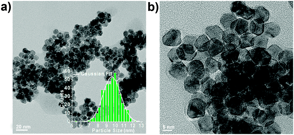 | ||
| Fig. 1 Representative TEM images of PtNi2 NPs before supporting. The inset in (a) is the corresponding particle size distribution. | ||
X-ray diffraction (XRD) patterns (Fig. S1, ESI†) show that all of the PtNi2 catalysts exhibit face-centred cubic structures, without a single Pt or Ni phase. The characteristic diffraction peaks of PtNi2 NPs between Pt and Ni diffraction-peak positions can be indexed (111), (200) and (220) peaks based on JCPDS cards of Pt (No. 04-0802) and Ni (No. 04-0850). The full-width half-maximum (FWHM) values of (111), (200) and (220) peaks decrease after thermal treatment, indicating an increase in the crystallinity of PtNi2 NPs. The main peaks of PtNi2/Gr–CO shift toward a higher angle (Ni phase) compared with that of PtNi2/Gr, which indicates that some Pt atoms segregate and the other Pt and Ni atoms form the PtNix (x > 2) nanoalloy.
Advanced electron microscopy techniques were used for uncovering the shape, composition and fine structures of the supported PtNi2 NPs. The PtNi2 NPs are highly dispersive on the multilayer graphene in the PtNi2–Gr sample, as shown in the high-angle annular dark field-scanning transmission electron microscopy (HAADF-STEM) image (Fig. 2a). High-resolution TEM (HRTEM) observations reveal that the shape of PtNi2 NPs is polyhedral (Fig. 2b). The lattice fringes (200) and (111), d-spacing 1.90 Å and 2.12 Å, of PtNi2 with a characteristic acute angle of 53.7° were identified on the NPs, referring to the JCPDS cards (Pt: No. 04-0802, Ni: No. 04-0850, space group: Fm![[3 with combining macron]](https://www.rsc.org/images/entities/char_0033_0304.gif) m). Summarizing the analyses of HRTEM images, the exposed facets of PtNi2 NPs can be identified as the {002}, {111} and {220} planes (see the insets in Fig. 2b). However, only a few PtNi2 NPs with good crystallinity exist in PtNi2/Gr, and most of PtNi2 NPs are polycrystalline with the size of the constituent single crystalline domains in the range between 1.0 and 8.0 nm, as shown in the colored HRTEM images (Fig. 2c and d). It is consistent with the XRD pattern that the diffraction peaks with the broad FWHM values in Fig. S1 (ESI†). According to above structural information, a structural model was proposed, showing the random distributions of Pt and Ni in most of polycrystalline PtNi2 NPs (the lower-right inset in Fig. 2d).
m). Summarizing the analyses of HRTEM images, the exposed facets of PtNi2 NPs can be identified as the {002}, {111} and {220} planes (see the insets in Fig. 2b). However, only a few PtNi2 NPs with good crystallinity exist in PtNi2/Gr, and most of PtNi2 NPs are polycrystalline with the size of the constituent single crystalline domains in the range between 1.0 and 8.0 nm, as shown in the colored HRTEM images (Fig. 2c and d). It is consistent with the XRD pattern that the diffraction peaks with the broad FWHM values in Fig. S1 (ESI†). According to above structural information, a structural model was proposed, showing the random distributions of Pt and Ni in most of polycrystalline PtNi2 NPs (the lower-right inset in Fig. 2d).
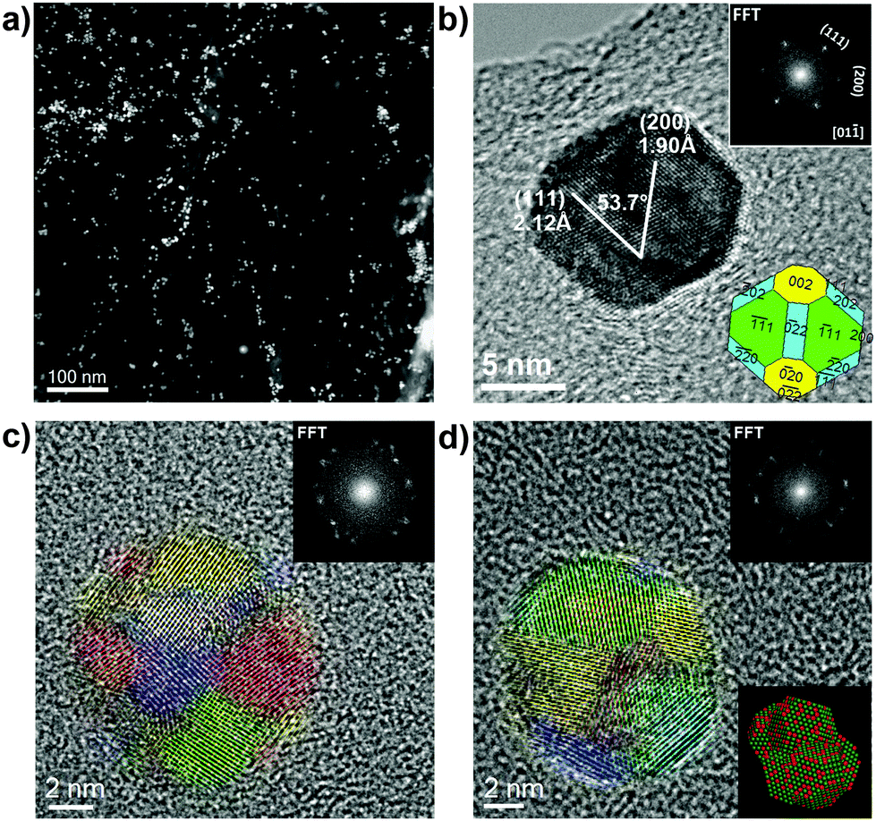 | ||
| Fig. 2 Low-magnification HAADF-STEM image of PtNi2/Gr (a), HRTEM images of polyhedral PtNi2 NPs with good crystallinity (b), and polycrystalline PtNi2 NPs (c and d). The top-right insets in (b–d) are the corresponding local Fast Fourier Transformation (FFT), and the lower-right insets in (b and d) are the shape and relevant atomic model (Pt-green, Ni-red) of PtNi2 NPs. The constituent single-crystalline domains are indicated in different colours in (c) and (d). | ||
Aiming to modify the surface structure of PtNi2 NPs, the PtNi2/Gr sample was thermally treated (300 °C) in Ar and CO gases. Fig. 3 shows the microscopic features of the PtNi2/Gr sample treated in Ar gas. The PtNi2 NPs remained highly dispersed on the supports except for slight agglomeration (Fig. 3a and Fig. S3a, ESI†). Most of PtNi2 particles were rearranged to polyhedral NPs with good crystallinity, which has been identified by HRTEM (Fig. 3b and Fig. S3b, ESI†). According to HRTEM analyses, the PtNi2 NPs are also encapsulated by the {002}, {111} and {220} planes (the inset in Fig. 3b). Moreover, there are some multiply twinned NPs in the PtNi2/Gr–Ar, displayed in Fig. 3e and f. This result is in accordance with the XRD results that the FWHM value of diffraction peaks decreased slightly compared with that before annealing. EDS elemental maps show the distributions of Pt and Ni are uniform in PtNi2 NPs (Fig. 3c and Fig. S3c, S5a, ESI†), indicating the Pt and Ni rearranged and formed a randomly mixed bimetallic type after thermal annealing in Ar gas. The atomic model is shown in Fig. 3d, displaying a three-dimensional structure with a random distribution of Pt and Ni in PtNi2 NPs.
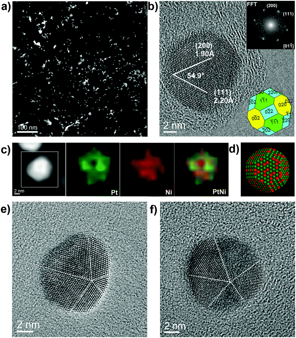 | ||
| Fig. 3 Low-magnification HAADF-STEM image of PtNi2/Gr–Ar (a), HRTEM images of polyhedral PtNi2 NPs with good crystallinity (b), multiply twinned PtNi2 NPs (e and f), EDS elemental maps (c) and relevant atomic models of PtNi2 NPs (d: Pt-green, Ni-red). The insets in (b) are the corresponding local FFT and shape of the PtNi2 NPs. The dashed white lines in (e) and (f) are the twin boundaries. | ||
The structures of the PtNi2/Gr treated in CO gas exhibited distinct changes. Low-magnification (S)TEM images show that the PtNi2 NPs are well distributed on the supports (Fig. 4a and Fig. S4a, ESI†). HRTEM reveals that all of the PtNi2 NPs retain the polyhedral shape with exposed {002}, {111} and {220} facets, as shown in Fig. 4b and Fig. S4b (ESI†). On these exposed planes, there exists some surface roughness (e.g. corner and step defects), ascribed to the atom migration induced by the CO thermal annealing. These NPs are of good crystallinity. Furthermore, EDS elemental mapping reveals that the Pt element is enriched on the surface of PtNi2 NPs, which formed the core (PtNix, x > 2)–shell (Pt) type (Fig. 4c and Fig. S4d, S5b, ESI†). The HR-STEM image in Fig. S4c (ESI†) clearly displays that brighter atoms (Pt) surround the Ni atoms, indicating a core–shell structure. Comparing the fine structures of PtNi2 NPs treated with thermal annealing in different gases, the shapes and surface structures of PtNi2 NPs can be tuned at the atomic level. Except for the microscopic features mentioned above, the composition of the serials of PtNi2 samples has been characterized by inductively coupled plasma mass spectrometry (ICP-MS) (Table S1, ESI†). The composition of the PtNix nanoalloy was kept nearly the same (the Pt/Ni atomic ratio was about 1/2) at the macroscopic scale.
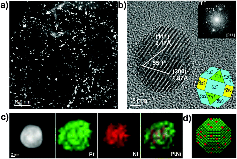 | ||
| Fig. 4 Low-magnification HAADF-STEM image of PtNi2/Gr–CO (a), HRTEM image of PtNi2 NP (b), EDS elemental maps (c) and relevant atomic model (d: Pt-green, Ni-red) of PtNi2 NPs. The insets in (b) are the corresponding local FFT and shape of PtNi2 NP. | ||
For studying the effects of the tuned microstructures and for illustrating the structure–function relationship, the methanol electro-oxidation reaction (MOR) was selected as the probing experiment. The MOR performance on PtNi2-based samples, PtRu/C and Pt/C was evaluated by cyclic voltammetry (CV) curves (Fig. 5a), and the normalized activity (current density) at the respective peak potential is shown in Fig. 5b. The better activity with 33% and 47% enhancement is presented in the PtNi2/Gr–CO, compared to those of other two PtNi2-based catalysts. The enhanced activity of the PtNi2/Gr–CO sample can be attributed to the rearrangement of Pt and Ni induced by the CO thermal treatment and the much more amount of Pt atoms segregating on the surface.11,27,28 The obtained best performance of the PtNi2-based catalysts is between those of PtRu/C and Pt/C, which is also comparable to other PtNi-based catalysts reported previously.29,30 The good CO tolerance of the PtNi2-based samples are represented by the ratio (1.1–1.3) of forward (If) and backward (Ib) peak currents.31 The CO-stripping of the PtNi2/Gr–CO sample was also investigated compared to that of the commercial PtRu/C catalyst. From the lower current density and peak potential, it could be observed that the PtNi2/Gr–CO sample shows a smaller amount of adsorbed CO and weaker CO adsorption on the surface during the electrocatalytic reaction than that of the commercial PtRu/C catalyst. In this case, the enhancement of CO tolerance can be explained by the electronic effect mechanism and the formation of Pt-rich shells.29,30 The transition metal Ni changes the electronic properties of the PtNix NPs via electron transfer between the Pt and Ni, which weakens the Pt–CO bond and suppresses the CO adsorption on the Pt rich surface. As for the stability, the MOR current density after 3000 s was also about 0.20, which is little lower than that of the 0.28 (Fig. 5a), as shown in Fig. 5d.
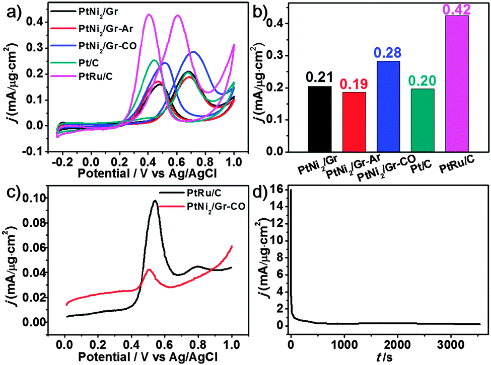 | ||
| Fig. 5 (a) CV curves of PtNi2-based catalysts PtRu/C and Pt/C in N2-saturated 0.5 M H2SO4 + 2 M CH3OH solutions at a scan rate of 50 mV s−1. (b) The normalized current density histogram at the respective peak potential for all catalysts. (c) CO-stripping voltammograms at 50 mV s−1 of PtNi2/Gr–CO and commercial PtRu/C (20 wt% Pt, 10 wt% Ru, Alfa Aesar) catalysts in 0.5 M H2SO4. (d) Chronoamperometric curve of MOR at 0.7 V on the PtNi2/Gr–CO catalyst. | ||
Several factors determine the surface segregation of the core–shell structure, which has been unravelled and interpreted based on experimental and theoretical studies,32–38 such as cohesive energy, surface energy, atomic radius and electronegativity. The surface segregation energy (SE) is the main driving force for the formation of core–shell structures.39 For instance, according to density functional theory (DFT) calculation, the SE of the 55-atom Ni-core and Pt-shell model is 0.42 eV. The core (Ni)–shell (Pt) structure is preferred when SE is positive, which is dominated by the smaller Wigner Seitz radius of Ni. It means that the compressive strain was relieved while the smaller atom goes into the core. This explanation is also supported by some related investigations.40–43 In this work, CO molecules play a principal role in the surface rearrangement. Based on the different CO adsorption energies (Ead) on Pt(111) and Ni(111) calculated by DFT,42 a reduction surface energy of about 0.67 eV per Pt atom rearranged to the surface was observed. Therefore, the segregation of Pt atoms is favourable during the thermal treatment in the CO surrounding. However, this phenomenon is not obvious in Ar gas due to the inert environment. Otherwise, the CO molecules adsorbed on the PtNi2 NPs surface can restrain the shape change and retain the polyhedral morphology.44,45
In summary, we present a method to obtain a Pt-rich shell structure of PtNi2 NPs supported on a multilayer graphene that retains the polyhedral shape with exposed {002}, {111} and {220} facets, which exhibits a better activity due to electronic and geometric effects in the MOR. Advanced electron microscopy unambiguously identified the structure evolutions of PtNi2 NPs from polycrystalline materials to randomly mixed and core–shell bimetallic structures induced by thermal annealing in Ar and CO gases. It offers a good example on the investigation of the structural evolution of bimetallic systems modified by different approaches, and reveals the structure–function correlation in chemical reactions. This work also provides a new insight into the interaction between CO molecules and metals, which could further help in the design of high activity nanoalloy catalysts by precisely tuning the shape, structure and composition.
We gratefully acknowledge the financial support provided by the National Natural Science Foundation of China (91545119, 21203215, 21133010, 51221264, and 21261160487), the Youth Innovation Promotion Association CAS (2015152), China Scholarship Council (PPP: [2014]6013) and “Strategic Priority Research Program” of the Chinese Academy of Sciences (XDA09030103). Dr G.-R. Zhang and Dr Y. Zhu are gratefully acknowledged for their stimulating discussions.
Notes and references
- V. R. Stamenkovic, B. Fowler, B. S. Mun, G. Wang, P. N. Ross, C. A. Lucas and N. M. Marković, Science, 2007, 315, 493–497 CrossRef CAS PubMed.
- R. R. Adzic, J. Zhang, K. Sasaki, M. B. Vukmirovic, M. Shao, J. X. Wang, A. U. Nilekar, M. Mavrikakis, J. A. Valerio and F. Uribe, Top. Catal., 2007, 46, 249–262 CrossRef CAS.
- J. Liu, L. Jiang, Q. Tang, B. Zhang, D. S. Su, S. Wang and G. Sun, ChemSusChem, 2012, 5, 2315–2318 CrossRef CAS PubMed.
- A. S. Aricò, S. Srinivasan and V. Antonucci, Fuel Cells, 2001, 1, 133–161 CrossRef.
- N. A. Hampson, M. J. Willars and B. D. McNicol, J. Chem. Soc., Faraday Trans. 1, 1979, 75, 2535–2543 RSC.
- D. F. van der Vliet, C. Wang, D. Tripkovic, D. Strmcnik, X. F. Zhang, M. K. Debe, R. T. Atanasoski, N. M. Markovic and V. R. Stamenkovic, Nat. Mater., 2012, 11, 1051–1058 CAS.
- D. F. van der Vliet, C. Wang, D. Li, A. P. Paulikas, J. Greeley, R. B. Rankin, D. Strmcnik, D. Tripkovic, N. M. Markovic and V. R. Stamenkovic, Angew. Chem., Int. Ed., 2012, 51, 3139–3142 CrossRef CAS PubMed.
- S. Guo, S. Zhang and S. Sun, Angew. Chem., Int. Ed., 2013, 52, 8526–8544 CrossRef CAS PubMed.
- S.-I. Choi, M. Shao, N. Lu, A. Ruditskiy, H.-C. Peng, J. Park, S. Guerrero, J. Wang, M. J. Kim and Y. Xia, ACS Nano, 2014, 8, 10363–10371 CrossRef CAS PubMed.
- R. Loukrakpam, J. Luo, T. He, Y. Chen, Z. Xu, P. N. Njoki, B. N. Wanjala, B. Fang, D. Mott, J. Yin, J. Klar, B. Powell and C.-J. Zhong, J. Phys. Chem. C, 2011, 115, 1682–1694 CAS.
- L. Gan, R. Yu, J. Luo, Z. Cheng and J. Zhu, J. Phys. Chem. Lett., 2012, 3, 934–938 CrossRef CAS PubMed.
- L. Gan, C. Cui, M. Heggen, F. Dionigi, S. Rudi and P. Strasser, Science, 2014, 346, 1502–1506 CrossRef CAS PubMed.
- W. Yu, M. D. Porosoff and J. G. Chen, Chem. Rev., 2012, 112, 5780–5817 CrossRef CAS PubMed.
- V. Stamenkovic, B. S. Mun, K. J. J. Mayrhofer, P. N. Ross, N. M. Markovic, J. Rossmeisl, J. Greeley and J. K. Nørskov, Angew. Chem., Int. Ed., 2006, 45, 2897–2901 CrossRef CAS PubMed.
- V. R. Stamenkovic, B. S. Mun, K. J. J. Mayrhofer, P. N. Ross and N. M. Markovic, J. Am. Chem. Soc., 2006, 128, 8813–8819 CrossRef CAS PubMed.
- Z. Xu, Y. Hou and S. Sun, J. Am. Chem. Soc., 2007, 129, 8698–8699 CrossRef CAS PubMed.
- J. Erlebacher, M. J. Aziz, A. Karma, N. Dimitrov and K. Sieradzki, Nature, 2001, 410, 450–453 CrossRef CAS PubMed.
- L. Gan, M. Heggen, R. O'Malley, B. Theobald and P. Strasser, Nano Lett., 2013, 13, 1131–1138 CrossRef CAS PubMed.
- D. Wang, Y. Yu, H. L. Xin, R. Hovden, P. Ercius, J. A. Mundy, H. Chen, J. H. Richard, D. A. Muller, F. J. DiSalvo and H. D. Abruña, Nano Lett., 2012, 12, 5230–5238 CrossRef CAS PubMed.
- B. Zhang and D. S. Su, Angew. Chem., Int. Ed., 2013, 52, 8504–8506 CrossRef CAS PubMed.
- B. Zhang, W. Zhang, L. Shao and D. S. Su, ChemCatChem, 2013, 5, 2586–2590 CrossRef CAS.
- B. Zhang, X. Ni, W. Zhang, L. Shao, Q. Zhang, F. Girgsdies, C. Liang, R. Schlogl and D. S. Su, Chem. Commun., 2011, 47, 10716–10718 RSC.
- B. Zhang, D. Wang, W. Zhang, D. S. Su and R. Schlögl, Chem. – Eur. J., 2011, 17, 12877–12881 CrossRef CAS PubMed.
- B. Zhang and D. S. Su, C. R. Phys., 2014, 15, 258–268 CrossRef CAS.
- D. S. Su, B. Zhang and R. Schlögl, Chem. Rev., 2015, 115, 2818–2882 CrossRef CAS PubMed.
- W. Zhang and W. T. Zheng, Phys. Chem. Chem. Phys., 2015, 17, 14461–14469 RSC.
- C. Cui, L. Gan, H.-H. Li, S.-H. Yu, M. Heggen and P. Strasser, Nano Lett., 2012, 12, 5885–5889 CrossRef CAS PubMed.
- P. Strasser, S. Koh, T. Anniyev, J. Greeley, K. More, C. Yu, Z. Liu, S. Kaya, D. Nordlund, H. Ogasawara, M. F. Toney and A. Nilsson, Nat. Chem., 2010, 2, 454–460 CrossRef CAS PubMed.
- A. B. A. A. Nassr, I. Sinev, M.-M. Pohl, W. Grünert and M. Bron, ACS Catal., 2014, 4, 2449–2462 CrossRef CAS.
- S. M. M. Ehteshami and S. H. Chan, Electrochim. Acta, 2013, 93, 334–345 CrossRef CAS.
- Z. Liu, X. Y. Ling, X. Su and J. Y. Lee, J. Phys. Chem. B, 2004, 108, 8234–8240 CrossRef CAS.
- H. Liao, A. Fisher and Z. J. Xu, Small, 2015, 11, 3221–3246 CrossRef CAS PubMed.
- R. Ferrando, J. Jellinek and R. L. Johnston, Chem. Rev., 2008, 108, 845–910 CrossRef CAS PubMed.
- A. S. Shirinyan and M. Wautelet, Nanotechnology, 2004, 15, 1720 CrossRef CAS.
- J. Greeley and M. Mavrikakis, Nat. Mater., 2004, 3, 810–815 CrossRef CAS PubMed.
- A. V. Ruban, H. L. Skriver and J. K. Nørskov, Phys. Rev. B: Condens. Matter Mater. Phys., 1999, 59, 15990–16000 CrossRef.
- C. Cui, M. Ahmadi, F. Behafarid, L. Gan, M. Neumann, M. Heggen, B. R. Cuenya and P. Strasser, Faraday Discuss., 2013, 162, 91–112 RSC.
- L. O. Paz-Borbón, R. L. Johnston, G. Barcaro and A. Fortunelli, J. Chem. Phys., 2008, 128, 134517 CrossRef PubMed.
- L.-L. Wang and D. D. Johnson, J. Am. Chem. Soc., 2009, 131, 14023–14029 CrossRef CAS PubMed.
- G. Wang, M. A. Van Hove, P. N. Ross and M. I. Baskes, J. Chem. Phys., 2005, 122, 024706 CrossRef PubMed.
- H. H. Hwu, J. Eng and J. G. Chen, J. Am. Chem. Soc., 2002, 124, 702–709 CrossRef CAS PubMed.
- K. J. J. Mayrhofer, V. Juhart, K. Hartl, M. Hanzlik and M. Arenz, Angew. Chem., Int. Ed., 2009, 48, 3529–3531 CrossRef CAS PubMed.
- Y. Gauthier, M. Schmid, S. Padovani, E. Lundgren, V. Buš, G. Kresse, J. Redinger and P. Varga, Phys. Rev. Lett., 2001, 87, 036103 CrossRef CAS PubMed.
- S. Y. Hwang, M. Zhang, C. Zhang, B. Ma, J. Zheng and Z. Peng, Chem. Commun., 2014, 50, 14013–14016 RSC.
- C. Cui, L. Gan, M. Neumann, M. Heggen, B. Roldan Cuenya and P. Strasser, J. Am. Chem. Soc., 2014, 136, 4813–4816 CrossRef CAS PubMed.
Footnote |
| † Electronic supplementary information (ESI) available: Experimental procedures and characterization data. See DOI: 10.1039/c5cc08978f |
| This journal is © The Royal Society of Chemistry 2016 |