
 Open Access Article
 This Open Access Article is licensed under a
 Creative Commons Attribution 3.0 Unported Licence
Transient electrochemistry: beyond simply temporal resolution
X.-S.
Zhou
a,
B.-W.
Mao
b,
C.
Amatore
c,
R. G.
Compton
d,
J.-L.
Marignier
e,
M.
Mostafavi
e,
J.-F.
Nierengarten
f and
E.
Maisonhaute
*g
aKey Laboratory of the Ministry of Education for Advanced Catalysis Materials, Institute of Physical Chemistry, Zhejiang Normal University, Jinhua, Zhejiang 321004, China
bState Key Laboratory of Physical Chemistry of Solid Surfaces, College of Chemistry and Chemical Engineering, Xiamen University, Xiamen 361005, Fujian, China
cCNRS UMR 8640 PASTEUR, Ecole Normale Supérieure-PSL Research University, Département de Chimie, Sorbonne Universités - UPMC University Paris 06, 24, rue Lhomond, 75005 Paris, France
dDepartment of Chemistry, Physical and Theoretical Chemistry Laboratory, University of Oxford, South Parks Road, Oxford OX1 3QZ, UK
eLaboratoire de Chimie Physique, CNRS UMR 8000, Université Paris-Sud, Bat 350, 91405 Orsay Cedex, France
fLaboratoire de Chimie des Matériaux Moléculaires, Université de Strasbourg et CNRS, Ecole Européenne de Chimie, Polymères et Matériaux (ECPM), 25 rue Becquerel, 67087 Strasbourg Cedex 2, France
gSorbonne Universités, UPMC Univ Paris 06, UMR 8235, Laboratoire Interfaces et Systémes Electrochimiques, F-75005 Paris, France. E-mail: emmanuel.maisonhaute@upmc.fr
First published on 6th November 2015
Abstract
Some physicochemical intrigues for which transient electrochemistry was necessary to solve the problem are summarized in this feature article. First, we highlight the main constraints to be aware of to access to low time scales, and particularly focus on the effects of stray capacitances. Then, the electron transfer rate constant measured for redox molecules in a self-assembled monolayer configuration is compared to the conductance measured through the same systems, but at the single molecule level. This evidences strong conformational changes when molecules are trapped in the nanogap created between both electrodes. We also report about dendrimers, for which a short electrochemical perturbation induces creation of a diffusion layer within the molecule, allowing the electron hopping rate to be measured and analyzed in terms of molecular motions of the redox centers. Finally, we show that transient electrochemistry provides also useful information when coupled to other methodologies. For example, when an ultrasonic field drives very fast movements of a bubble situated above the electrode surface, the motion can be detected indirectly through a modification of the diffusion flux. Another field concerns pulse radiolysis, and we describe how the reactivity (at the electrode or within the solution) of radicals created by a radiolytic pulse can be quantified, widening the possibilities of electrochemistry to operate in biological media.
Emmanuel Maisonhaute obtained his doctoral degree at the Ecole Normale Supérieure (Paris, France) under the supervision of Christian Amatore in 2000. After a postdoctoral work with Richard Compton (University of Oxford, United Kingdom) during 2000–2001, he returned to Paris as an assistant professor in the group of Christian Amatore and was promoted full professor in 2008. In 2010, he moved to the Laboratoire Interfaces et Systémes Electrochimiques at Université Pierre et Marie Curie (Paris). He received the Instrumentation Prize of the French Chemical Society in 2008 in recognition for his scientific contributions in ultrafast electrochemistry. His research aims at coupling electrochemical detection to other physicochemical methods. |
Introduction
In any physicochemical method the temporal resolution is an issue, because at each stage, new phenomena are evidenced. In electrochemistry, the measurement timescale is intimately linked to the diffusion processes that occur in the vicinity of the electrode.1,2 The race for accessing short times was initiated so as to characterize heterogeneous electron transfer kinetics or transient radicals. The different strategies to solve that purpose may be classified in two main categories. In the first one, the size of a stationary diffusion layer δ is controlled finely by the technique. The characteristic timescale tchar is then derived simply using eqn (1):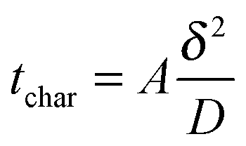 | (1) |
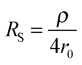
The second strategy, to which belong the examples depicted in this paper, involve direct time-dependent perturbations. The prominent methods are cyclic voltammetry,2 chronoamperometry,7,8 impedance spectroscopy9 and their variations. However, applying a short perturbation does not warrant an effective access to lower time scales.10 This is evidenced considering the simplified electric scheme of an electrochemical interface displayed in Fig. 1. This scheme contains the solution resistance RS, which depends on the solution composition and electrode geometry, the double layer capacitance CDL that takes into account compensation of the electrode charge by the ions from the solution and the faradaic impedance ZF. ZF is a very complex impedance that incorporates the mechanism which needs to be elucidated. The cell time constant τ is defined by:
| τ = RSCDL | (2) |
 | (3) |
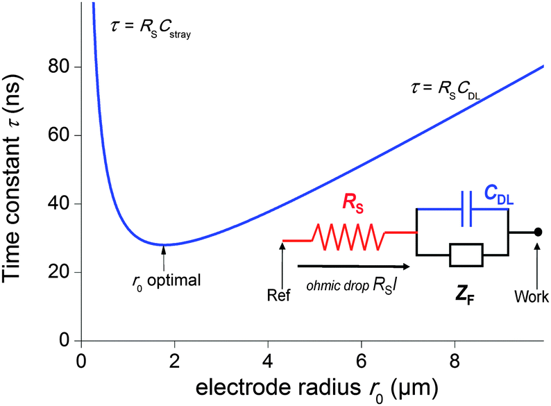 | ||
| Fig. 1 Simplified electric scheme of an electrochemical interface featuring the solution resistance (red), the double layer capacitance (blue) and the faradaic impedance (black). Blue curve: evolution of the time constant τ = RSCglobal as a function of the electrode radius r0 when the stray capacitances are not negligible (see text). | ||
Therefore, one may be tempted to use nanoelectrodes which are routinely accessible presently to perform even faster measurements. But before, the capacitance of the whole system needs to be reevaluated. As a representative example, let us consider a capacitance per surface area of Csurf = 10 μF cm−2 and r0 = 2.5 μm so that the double layer capacitance is only about 2 pF. Such small value stresses that for very small electrodes the global capacitance Cglobal, incorporating all stray components Cstray from the electrochemical cell and electronic board of the potentiostat needs to be considered:
| Cglobal = CDL + Cstray = Csurfπr02 + Cstray | (4) |
| τ = (ρCsurfπr0)/4 + (ρCstray)/(4r0) | (5) |
| r0 = (Cstray/(πCsurf))1/2 | (6) |
Overall, though transient and steady state methodologies rely on similar concepts, some systems require a specific technique to unravel the mechanism. For example, all time dependent systems definitely require transient measurements. Also, even if in theory SECM may attain nanosecond timescales, in practice to the best of our knowledge no extremely fast electron transfer rate have been measured.
In this review, we will focus onto some aspects of our research solved through the very good temporal resolution of our potentiostat. The first section will aim at comparing the results obtained by ultrafast cyclic voltammetry and single molecule measurements through the same molecular systems. Then, we will show how diminishing the experimental timescale provides unique information about electron hopping between the different redox centers of a single macromolecule. We will end this review by describing how the coupling of transient electrochemical measurements (mainly at constant potential) with other transient methodologies such as acoustic cavitation and pulse radiolysis provides useful information about very complex physicochemical mechanisms induced by non-electrochemical perturbations.
Electron transfer through electroactive molecules: transient versus single molecule approaches
The dream of molecular electronics would be to build an entire signal processing unit only with molecules. But to be competitive with top down methodologies, several problems need to be considered. First, the molecular design should allow a function. It has been now demonstrated that molecules are indeed able to treat electrical, optical or even magnetic information. This has been demonstrated mostly by relying onto experiments performed on collection of molecules. Another problem is related to the individual organization of each structure. In this aspect, it is now common to organize some nanoobjects over several hundreds of nanometers (the limitation often comes from the substrate) but usually the same entity is assembled.23,24 Moreover, these organizations often rely on weak interactions so more robust structures need to be produced for practical applications.The first property to be tested was the ability of a single molecule to propagate a signal, i.e. to act as a molecular wire. This can be performed by placing an electron donor and an acceptor at each end of a linear entity and inducing a photochemical activation or pulse radiolysis. For example, this was thoroughly studied in peptides25 or in DNA26 but also in many other molecular wires.27
In electrochemistry, the donor or the acceptor can be replaced by an electrode. Then, the measured quantity is the heterogeneous standard rate constant kET.1,2 Several experimental protocols are available to deduce this parameter, and among them transient ones such as chronoamperometry and ultrafast voltammetry are rather straightforward. The theoretical framework to interpret the evolution of kET with the potential E has been initially introduced by Marcus.28 Later, Chidsey proposed a formulation particularly adapted for electroactive self-assembled monolayers that takes into account the Fermi distribution of electronic levels in the electrode:29
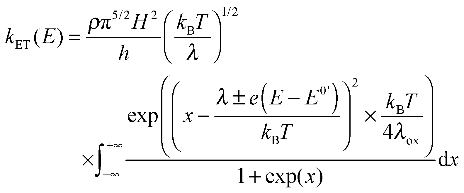 | (7) |
| k0ET = k0ET(d = 0)exp(−βd) | (8) |
Another more recent approach to test the conduction through molecular wires consist of connecting single molecules between two electrodes. The quantity measured is then the conductance G through the molecule, a steady-state value.32 In this approach, the benefit is that single entities are addressed, but no temporal resolution has been until now investigated. Several experimental configurations are available, but those deriving from the scanning tunneling microscope break junction (STMBJ) that emerged from 2003, and presently implemented in several groups, are the only ones that allow performing measurements under electrochemical conditions.33–37 For that, a metallic STM tip, most often a gold one, is insulated so as to minimize the leakage current. It is then approached towards a surface modified with the molecule of interest until contact. During retraction, successive plateaus are observed, each one corresponding to a definite number of molecules contacted between both electrodes.
In the framework of superexchange, theoretical equivalence between conductance measurements through a bridge and electron transfer from an electrode to a redox center separated from the electrode by the same bridge has been examined by several authors and reinforce the intuitive idea that electron transfer rate constants should be correlated to single molecule conductance.38–40 Like k0ET, G indeed depends onto H according to:
 | (9) |
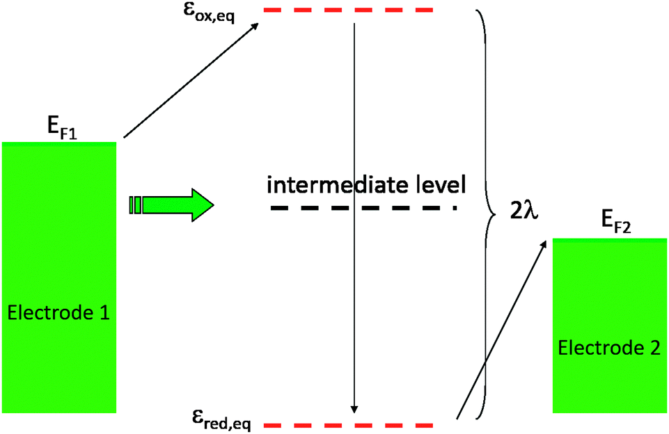 | ||
| Fig. 2 Energy levels distribution. Green: level distribution in the electrodes. Red: energy levels at equilibrium. Black: intermediate level corresponding to out of equilibrium situation that can transiently efficiently couple both electrodes. | ||
In this context, we tried to explore and relate k0ET to the conductance G onto the three very different electroactive molecules 1–3 displayed in Fig. 3.45 Molecules 1–3 differ widely by the nature of their redox center, bridging unit and metal-contacting atoms but have similar size (about 1.9 nm).
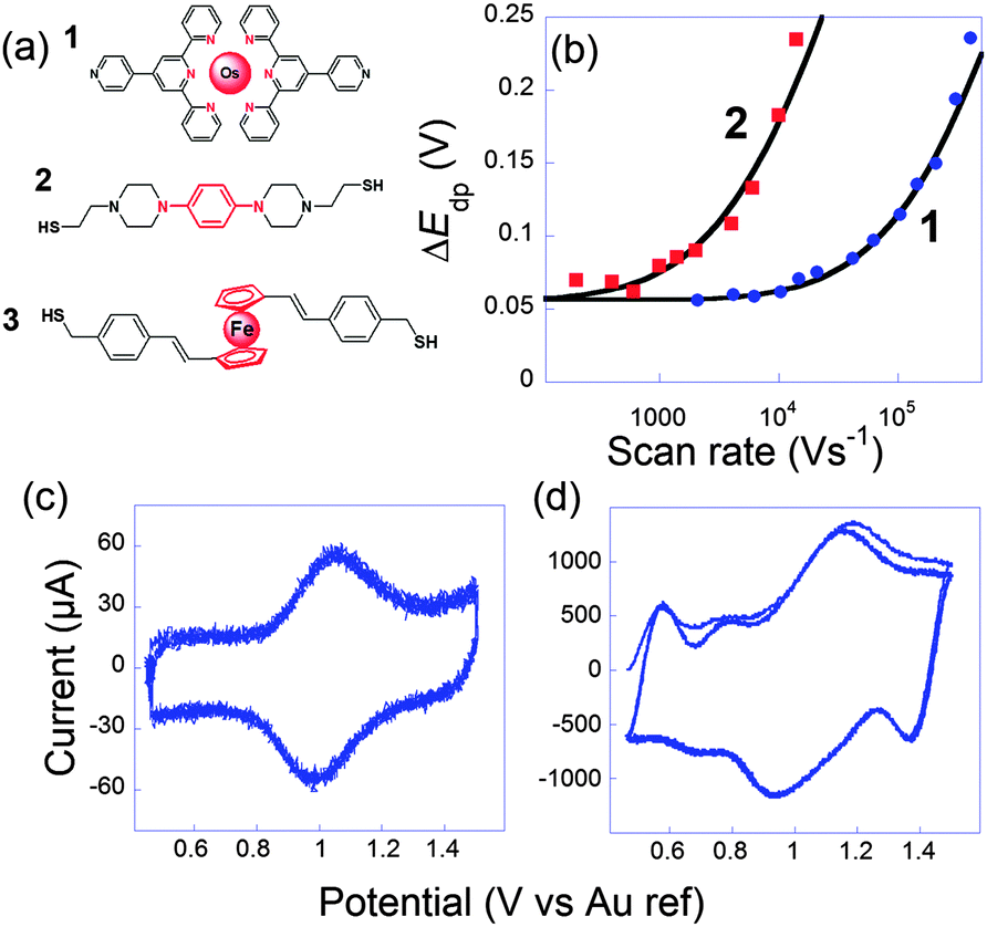 | ||
Fig. 3 (a) Molecules 1, 2 and 3 used to perform ultrafast and single molecule measurements. (b) Peak to peak potential differences obtained for 1 (blue dots) and 2 (red squares). Black lines: simulations for k0ET = 2.0 × 10⁶ s1 (1) and 7 × 10⁴ s−1 (2). (c and d) Cyclic voltammograms of 1 at (b) 10![[thin space (1/6-em)]](https://www.rsc.org/images/entities/char_2009.gif) 400 V s−1 and (c) 407000 V s−1, three consecutive scans, no average. Electrolyte: H2O + 1 M NaClO4. Adapted from ref. 45. 400 V s−1 and (c) 407000 V s−1, three consecutive scans, no average. Electrolyte: H2O + 1 M NaClO4. Adapted from ref. 45. | ||
The first probe 1 was an OsmiumII bisterpyridine complex that may be reversibly oxidized to OsIII. Fig. 3 presents cyclic voltammograms at different scan rates obtained for 1 onto gold ultramicroelectrodes. At low scan rate (<10000 V s−1), the peaks are almost symmetric and bell-shaped because the OsIII/OsII ratio follows the equilibrium distribution given by the equilibrium potential (Nernst law). As the scan rate increases, the peak potentials shift because the kinetic window, proportional to Fν/RT is fast enough to compete with k0ET. k0ET is then easily deduced by fitting the peak to peak difference with reference curves obtained numerically. For that complex, k0ET = 2.0 × 10⁶ ± 0.5 × 10⁶ s−1 was deduced.
Molecular conductances were determined by the STMBJ method. Fig. 4 presents typical conductance curves obtained when the sample was set at −0.3 V per Pt (pseudo reference electrode). Under these conditions, from statistical analysis of a large number of curves (Fig. 4c), an average single molecular conductance of 17.8 nS was determined. Furthermore, the sample potential was varied from −0.3 to 0.3 V while the bias remained fixed at 50 mV to cover the whole electroactivity range of the complex. This evidenced a clear modulation of the conductance by the redox switching from 17.8 nS at −0.3 V to 2.1 nS at +0.3 V, which provides an on-off ratio of 8.5 (Fig. 4d).
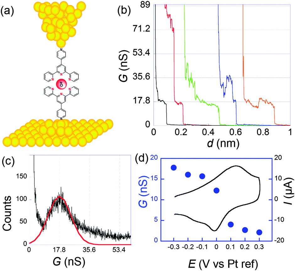 | ||
| Fig. 4 (a) Schematization of a scanning tunneling microscopy break junction experiment. (b) A few conductance traces obtained for 1 at a sample potential of −0.3 V per Pt and a bias of 50 mV. Electrolyte: 0.1 M NaClO4 aqueous solution. (c) Histogram obtained from the selection of 211 out of 1000 conductance traces. (d) Filled circles: molecular conductance versus sample potential. Black line: cyclic voltammogram. Adapted from ref. 45. | ||
System 2 conversely contains saturated parts in the bridges, so that the redox center is better isolated from the electrodes. As a consequence the rate of electron transfer was found much slower: k0ET = 7 × 10⁴ s−1. Since the resistance was higher, we observed more noise in the conductance curves, and it was harder but nevertheless possible to observe well-defined steps. From the resulting histograms constructed at different potentials, we deduced that the conductance shifts from 0.79 nS in the reduced state to 0.33 nS in the oxidized one. Modulation by the potential is thus smaller than for 1 but still appreciable. It has to be underlined that for thiol–gold bonds, several microscopic configurations of the contacts leading to different conductances have been evidenced.46–48 Here, we refer to the so-called “high conductance” for which the sulphur contacts three gold atoms since we believe this is the most stable configuration, thus closer to the one obtained in self-assembled monolayers.
For system 3, single molecule conductance was measured at reduced (−0.1 V), oxidized (+0.4 V) and intermediate (+0.2 V) redox states. Very surprisingly, the molecular conductance remained almost unchanged with potential, at a value close to 9.4 nS. The high conductivity was in agreement with the one determined previously in a mechanically controlled break junction experiment without potential control (9.7 nS).49 The conductance invariance observed for 3 severely contrasts with the behavior of systems 1 and 2 and with any other redox molecules that have been reported so far. Onto similar systems, and in agreement with indirect laser induced temperature jump measurements performed by Chidsey et al.,31 we previously confirmed that the rate constant was nearly independent of the molecular length, as long as redox centers are accessible to counterions. k0ET was about 5 × 10⁶ s−1 for this family.50
In the theoretical framework provided by Kuznetsov and Ulstrup,41,42 the absence of any current maximum near the standard potential indicates a “soft-gating” configuration. As a consequence, the redox levels somehow escape to be in between the Fermi levels of the electrodes. They however still play a role in the coupling so that variations are observed when the sample potential is modified. Here, a potential variation modulates the coupling factor H but the mechanism still remains a superexchange. This demonstrates that large conformational fluctuations occur in the nanogap. It is noticeable that the larger on/off current ratio is higher for the more rigid system 1. In the extending nanogap more degrees of freedom may be available for flexible molecules so that the situation may thus greatly differ from the behaviour in single component type of self-assembled monolayer where the molecules are well-organized. We then relied on the superexchange framework to evaluate the coupling factor between both electrodes.38
The coupling factors H were evaluated for a range of reasonable reorganization energies. Results are reported in Fig. 5. For ferrocene and phenylene diamine derivatives λ is in the range 0.6–1 eV. No reported value exists for 1, but it may be expected to fall in the same range. For system 3 we obtain an excellent agreement for λ = 0.9 eV, a very plausible value for ferrocenyl derivatives. However, in the junction, reorganization energies can reach smaller values than when the redox centers are fully accessible to solution. This may be correlated to the invariance of k0ET with the molecular length. For 1 and 2, H obtained at low potentials in the STMBJ configuration, therefore in the situation for which the self-assembled monolayer is created, is clearly higher than the value deduced by ultrafast voltammetry. Since electron transfer operates over a longer distance in the conductance mode, this result is rather surprising, particularly for 2 whose redox center is connected through long saturated bridges. A possible explanation involves a preferential conformation in the nanogap for which the conductance would be very high compared to the relaxed one for which cyclic voltammetry is performed. This phenomenon has been demonstrated by temperature dependence measurements for dithioalkyls in the gas phase.51 Conformational changes may be induced by the current itself, or by the tip movement while or after the contact is established. A softer method to realize the contact could minimize the molecular fluctuations and lead to a better correlation. Recent evolutions of the STMBJ technique should allow scrutinizing this issue by allowing conductance measurements at various nanogap width (thus at different molecular conformations) and solve this issue.52 These results, and particularly those for 3, although showing a qualitative correlation between k0ET and G enlightens the need for further theoretical and experimental insights to fully understand the performances of complex molecular systems. It also emphasizes the need for independent and complementary experimental methods to estimate molecular devices performances and usefulness.
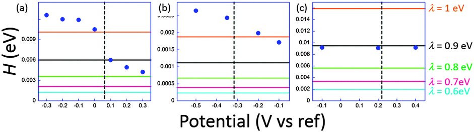 | ||
| Fig. 5 Estimated electronic coupling elements from conductance measurements (filled circles) and from ultrafast voltammetry (horizontal lines) for a range of reorganization energies ranging from 0.6 to 1 eV for 1 (a), 2 (b) and 3 (c). Vertical dashed line indicates standard potential. Potential scale refers to Pt for (a) and (b), and to SCE for (c). Adapted from ref. 45. | ||
Electron hopping within giant molecules
When redox centers are too far from the electrode, H may be too small to drive efficient communication with the surface. However, when several redox centers are present in the molecule, successive electron transfers may occur so that finally the electrochemical perturbation may reach entities placed at several nanometers from the surface. This is the way Nature transfers electrons in many proteic systems such as hydrogenases,53 and is also debated for DNA.26,54 In electrochemistry, electron hopping was initially considered by Dahms and Ruff55,56 and later studied onto polymers by Saveant et al.57 We explored electron hopping in various dendrimer systems and developed an adequate theory to understand the signal propagation within these structures.58–63 In comparison to polymers, these macromolecules present the advantage to be monodisperse and to form well-defined monolayers. When adsorbed onto electrodes, such compounds can be schematized as truncated spheres onto which are positioned the redox entities.59 For example, let us consider the system C60Fc bearing 10 electroactive ferrocene entities represented in Fig. 6.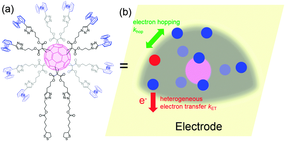 | ||
| Fig. 6 Molecular formula (a) and schematization (b) of C60Fc adsorbed onto an ultramicroelectrode. | ||
With this geometry, we considered that only the redox centers adjacent to the electrode surface may undergo electron transfer from the electrode. Then, intramolecular electron exchanges (the electron hopping steps) occur through:
 | (10) |
 | (11) |
On the other hand, if the scan rate is fast enough, the diffusion layer extension (δ), becomes smaller than the dimension of the molecule, and a semi-infinite diffusion response is expected. This translates into a ν1/2 dependence of the current. By careful consideration of this sort of diffusional response, information can furthermore be gained about the topology of the space in which the diffusive process occurs, giving insight into whatever deformation of the dendrimer, if any, takes place upon adsorption to an electrode surface. The transition between both regimes may then be evidenced by plotting I/ν1/2versus ν1/2.
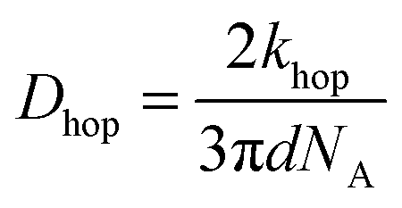
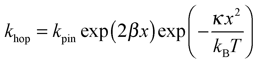
In Fig. 7, at low ν, the current is proportional to ν. However, departing from the cases we previously analyzed, at larger ν a diffusional tail appears in the voltammogram and the slope diminishes but does not reach a plateau as expected. In our view, some redox centers very close to the electrode remain independent, thus keeping a contribution proportional to ν. From the slope ratios, we deduced that two redox centers out of ten were independent. The analysis of the eight centers that were interacting together revealed that Dhop spanned the range 1.9 × 10⁻⁹ cm2 s−1 < Dhop < 1.3 × 10⁻⁸ cm2 s−1 so that khop was deduced to be 3.3 × 10⁵ L mol−1 s−1 < khop < 2.2 × 10⁶ L mol−1 s−1. This value may be compared to the one deduced by NMR line broadening or stop flow methods pertaining for the self exchange between two independent ferricinium and ferrocene in close contact: kSE = 7.3 × 10⁶ ± 0.3 × 10⁶ L mol−1 s−1. Our values are then smaller compared to the one in which the redox centers are touching each other. However, considering that the ferrocene entities are pinned at the apex of an icosahedron, and taking 10 nm−1 as minimum value for β since electron transfer occurs through the solvent, we estimated that 2.9 × 10² < kpin < 4.0 × 10³ L mol−1 s−1. This value is much smaller than khop, which suggest that molecular motion favors electron transfer, but that the linking chains restrain the electroactive entities mobilities so that kpin < khop < kSE. Considering that the redox centers were in a harmonic well, khop can then be expressed as:
 | (12) |
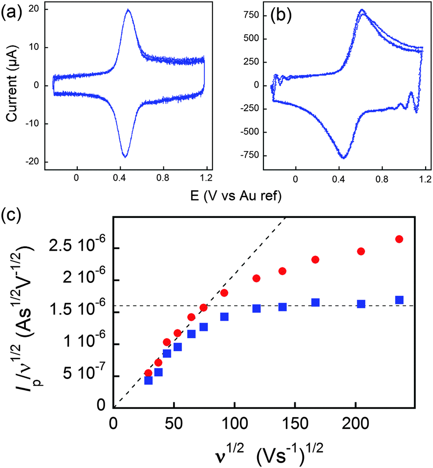 | ||
| Fig. 7 (a and b) Voltammograms of C60Fc at 836 (a) and 55850 V s−1 (b) in acetonitrile +1 M tetra-n-butylammonium tetrafluoroborate. (c) Peak current evolution with the scan rate. Red dots: experimental data. Blue dots: corrected data featuring a diffusion plateau at large scan rates. Adapted from ref. 62. | ||
Dendrimer ultrafast electrochemistry represents to the best of our knowledge the first example for which dynamic interactions between redox centers inside single macromolecules could be deciphered. Somehow, we evidenced similar concepts to those relevant to Förster resonance energy transfer approaches in photophysics.64,65 On the other hand, elucidating the charge propagation in these structures is a pre-requisite prior incorporating them in (opto)electronic devices.
Ultrafast detection of acoustic bubble movement
Another original application of ultrafast electrochemistry concerns the detection of a fast moving object thanks to the perturbation induced on the flux of electroactive material towards an electrode.66 The resulting signal is then a convolution between the movement and the diffusion layer evolution. The original example considered below demonstrates how extremely fast moving speeds can be detected by transient electrochemistry. Here, electrochemistry acts as a nanometric zoom to indirectly visualize the evolution of the interface.67–70When ultrasound is applied to a solution, for example using a ultrasonic horn, the cohesive forces of the liquid may be overcome when the acoustic pressure exceeds a threshold value. Gas-filled bubbles then grow, especially near inhomogeneities such as solid impurities, surface kinks or tiny gas bubbles. In solution, subsequent evolution varies from oscillating behavior for moderate acoustic pressures to transient one for larger ones. Very high local temperatures and pressures can thus be achieved. Those may be beneficial for electrosynthesis or electroanalysis since the bubbles clean the electrode surface and accelerate greatly the mass transport.71,72 A common thought previous to our work was that near a surface the implosion of the bubble was asymmetric leading to a toroidal bubble through which a microjet impacted the surface. In fact, this microjet has been observed for large bubbles stimulated at low frequencies73 or for cavities produced by a laser pulse,74 thus under very different conditions than those applied usually in sonochemistry,74i.e. at frequencies ranging from 20 kHz up to 1 MHz. We used our ultrafast electrochemical equipment and ultramicroelectrodes to visualize indirectly a single bubble evolution through the current induced by its movement.67,68 Firstly we considered chronoamperometry at a single electrode where [Fe(CN)6]3− is continuously reduced to [Fe(CN)6]4−, with the electrode held at −0.8 V versus a platinum pseudoreference. Fig. 8 shows typical chronoamperograms for a 29 μm diameter platinum electrode under insonation.
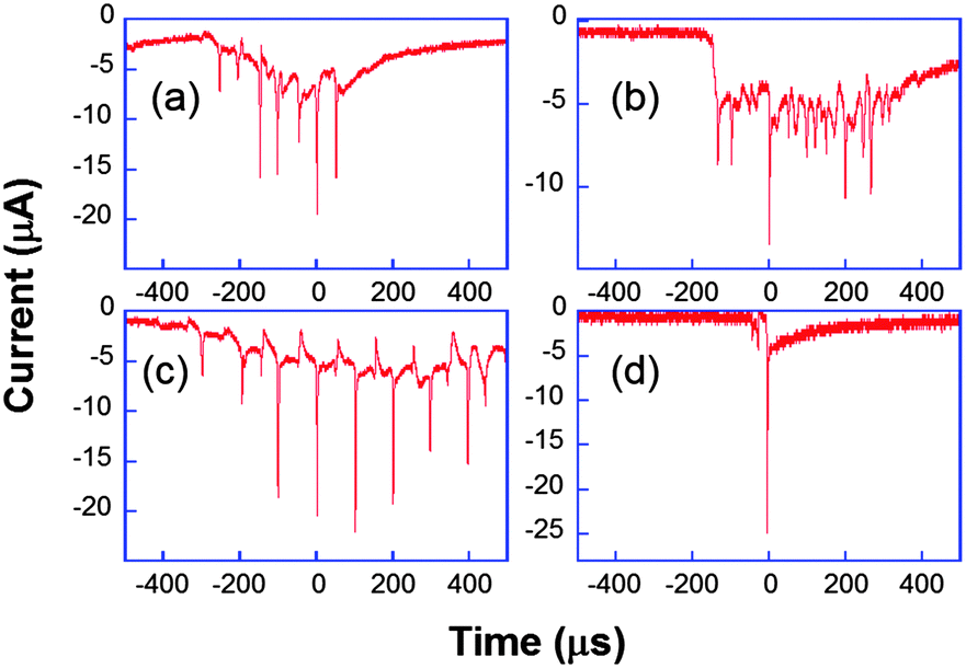 | ||
| Fig. 8 Chronoamperometric current obtained for the reduction of K3[Fe(CN)6] (50 mM) in aqueous KNO3 under ultrasound power of 8.9 W cm−2 at a 29 μm diameter platinum electrode. Horn-to-electrode distances are 10 mm (a–c) and 1 cm (d). Adapted from ref. 67. | ||
Fig. 8a–c are different transients obtained under the same conditions. The observed peaks are attributed to cavitational bubble activity in the vicinity of the electrode. The local acoustic pressure can be increased by reducing the horn-to-electrode separation and a transition is observed from stable towards transient cavitation (see Fig. 8d). Otherwise, the current measured when no bubble was close to the electrode was much higher than the spherical diffusion-limited current under silent conditions. Since it was found to be proportional to the electrode area for a range of electrode diameters, this was attributed to macroscopic acoustic streaming, which leads to a convection-dominant response. Returning to the chronoamperograms, it is obvious that the entire millisecond signal cannot be described as a single peak as suggested elsewhere.75Fig. 8 shows that the signal comprises many thin spikes whose rise time can be much less than one microsecond. In some cases, these narrow spikes can be periodic with a frequency of 10 or 20 kHz (Fig. 8c and a, respectively), leading to larger currents that can be up to 200 times higher than the steady-state diffusion-limited current under silent conditions. Higher harmonics of the driving frequency can also be observed (see Fig. 8b).
Complementary experiments by fast scan cyclic voltammetry were performed. In Fig. 9, the cavitation peak is preceded by a long depletion in the voltammetric current, indicating the presence of an obstacle to the diffusion layer growth.
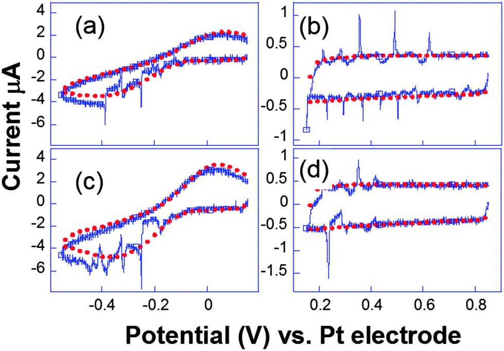 | ||
| Fig. 9 Cyclic voltammograms recorded simultaneously ((a and c) and (b and d)) for two electrodes separated by 206 μm. Conditions: K3[Fe(CN)6] (50 mM) in KNO3 (0.1 M), horn-to-electrode distance 1 cm, electrode diameters 29 μm. Voltammograms under silent conditions (red) and subject to 8.9 W cm−2 insonation (blue) are represented. Adapted from ref. 67. | ||
Analogous behaviour was observed with scan rates as high as 104 V s−1 or even in the capacitive current as displayed in Fig. 9b and d. This suggests that the bubble grows in the close vicinity of the electrode surface: after the spike, the end of the voltammogram overlays with the silent voltammogram, as does the back peak corresponding to the ferrocyanide reoxidation. This is proof that the diffusion layer structure returns to normal after a bubble collapse occurs. Experiments with a single microelectrode show thus that the cavitation activity is complex. Oscillations at harmonics of the driving frequency are observed with cyclic voltammetry experiments proving that the bubble is in the close vicinity of at least a part of the electrode. Due to the complexity of activity, the spatial dependence of a single cavitational event is difficult to assess since no theoretical model immediately allows easily relating the signal obtained to the space variables. For this purpose microelectrode arrays were used, because they allow a direct visualization of the spatial extension of the bubbles.76 The chronoamperometric experiments presented above were repeated as before but the current was simultaneously recorded on different electrodes of the array. A typical array is shown in Fig. 10.
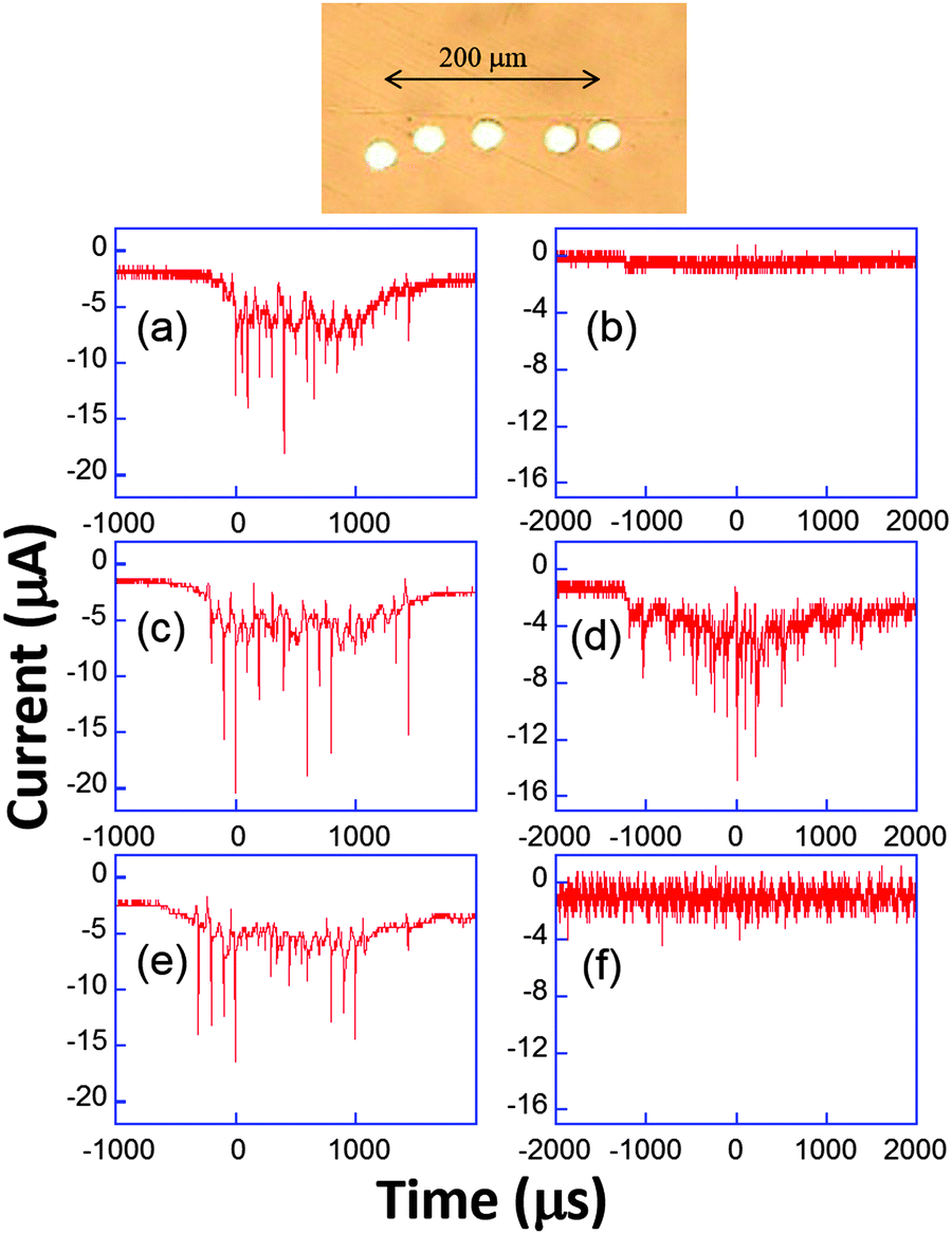 | ||
| Fig. 10 Top: Example of microelectrode array. Bottom: Chronoamperometric current recorded simultaneously (a, c and e or b, d and f) on three electrodes using 50 mM K3[Fe(CN)6] in aqueous KNO3 (0.1 M). Adapted from ref. 67. | ||
The appearance of cavitation peaks on the three electrodes is observed almost simultaneously in Fig. 10a, c and e. Since it is unlikely that two independent bubbles appear at around the same time on different electrodes and with the same peak shape and lifetime, it is inferred that the signals are induced by the same bubble. Analogous synchronous events could be recorded for distances as large as 0.8 mm using different electrode-to-electrode separations. Furthermore, in Fig. 10b, d and f, where the interelectrode distance was less than 5 μm, a signal is observed only on the central electrode. From geometrical considerations, we can estimate that the bubble size there is less than 40 μm. This behavior suggests that a wide distribution of bubble sizes is produced, including bubbles of sizes less than 40 μm. In experiments, the same type of signal with nearly the same current amplification was observed, suggesting that in these type of experiments (20 kHz, interfacial cavitation) the absence of a microjet, or if a microjet was present, it resulted ineffective in controlling the magnitude of the electrode signal, since different signals would be expected for electrode positions below the jet, below the toroidal bubble and outside the bubble. Furthermore, cyclic voltammetry experiments revealed that when cavitational activity is seen on two different electrodes, generally both show a depletion in the voltammogram (see Fig. 9) either in the faradaic current or in the background current. Since this depletion is attributed to blocking of the surface, bubbles are thus more likely to be hemispherical or flatter rather than spherical as often assumed prior to our study.
On the trace displayed in Fig. 11b a more quantitative interpretation was possible. Here, the chronoamperometric trace was obtained for the reduction of [Ru(NH3)6]3+ in aqueous solution.
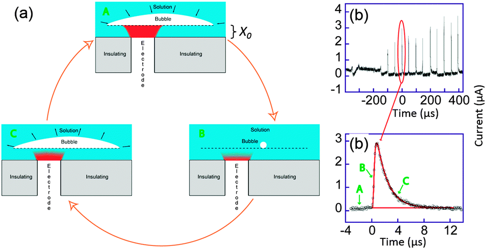 | ||
| Fig. 11 (a) Sketch of bubble evolution near a surface. (b) Single bubble cavitation chronoamperometric current recorded for [Ru(NH3)6]Cl3 (10 mM) in aqueous KNO3 (0.1 M) under sonication at 20 kHz. Conditions: horn-to-electrode distance 7 mm, insonation power 8.9 W cm−2, electrode diameter 32 μm. (c) Zoom on a single spike (circles) and simulation (line). For simplicity reduction currents are here positive. Adapted from ref. 68. | ||
We considered a simple model of bubble implosion close to a surface as sketched in Fig. 11a. Firstly, we introduced the distance x0 between the disk electrode and the bubble wall, and considered a potential sufficiently negative to ensure that the concentration C of electroactive species at the electrode surface was zero. Therefore, diffusion of the electroactive species from the solution (C = C0) toward the electrode (C = 0) occurs. At time t < 0, the bubble grows and covers the electrode. Collapse occurs at t = 0 and bulk solution instantaneously replaces the bubble but the thin layer (TL) above the electrode x0 is still fully electrolysed: the concentration of the electroactive species in TL and the current are then both zero. After the collapse, bulk solution instantaneously replaces the bubble above TL and diffusion of the electroactive compound inside TL occurs. This model neglects macroscopic streaming as this has been shown to correspond to larger diffusion layers than are actually observed experimentally for the transient, as opposed to the steady-state response. After a time t0, it is believed that the bubble expands again, thus recreating another thin layer of the same thickness x0. The electrode is then blocked again and the current drops to zero within a time proportional to x02/(2D), where D is the diffusion coefficient of the redox system.
Theory based on this model was used to fit all the cavitation spikes shown in Fig. 11b. The peak height and width was matched with the working curve data. This allowed values of x0 and t0 be theoretically deduced.68 Comparing the experimental voltammograms with the simulations gave a very good fit for several peaks whereas other peaks could not be described by the theory developed. The peaks for which the model was unsuccessful possibly resulted from a different bubble/electrode distance x0 before and after the collapse, although x0 would remain of the same order of magnitude in size. It is not unexpected to observe such variations under the conditions used, since the precise behaviour of the bubble results from a complex acoustic field influenced by the presence of neighbouring bubbles as well as by the local surface roughness. A large range of values for t0 were obtained, which reveals that even in this apparent periodic signal a partially chaotic bubble behaviour exists. The experimental t0 values suggest that most of the time the bubble covers the electrode, which is a similar conclusion to that of Leighton based on simulations.77–79 Furthermore x0 values were shown to range between 45 and 75 nm, which implies only small variations of x0 over the whole chronoamperogram. These variations are consistent with the quasi steady-state current observed between the spikes. This current is due to a slow solution penetration in the bubble electrode gap that grows at velocities of ca. 1 × 10⁻⁴ m s−1. The presence of a thin layer of a solution between the bubble wall and the surface could thus be established and quantified.
The deduced values of t0 gave an average value of 0.2 μs. This gives an average minimum wall velocity ranging from 160 to 320 m s−1 depending on the bubbles' position.77–79 Though the nanometric evolution of the interface can not be optically visualized, recording of the bubble size, shape and position as a function of time may be a first step to introduce more parameters in the model and unravel the complex behaviour of these fast evolving triple boundaries interfaces. Thanks to ultrafast electrochemistry, the effects of ultrasound irradiation could be rationalized which is of major importance in many fields of physics (for the example semi-conductor industry), chemistry and biology where ultrasonic bath treatment have become a standard operation.69,70
Pulse radiolysis coupled with transient electrochemistry
In molecular electrochemistry, the characteristic shape of the voltammogram and its evolution with the scan rate or concentration of reactants are determined by a subtle interplay between thermodynamic parameters such as the standard potentials and the kinetic rates of homogeneous or heterogeneous chemical reactions.2 One strategy to extract the standard potentials is then to increase the scan rate until competing with the reaction of interest, which represents another advantage of ultrafast cyclic voltammetry. Ultrafast cyclic voltammetry nevertheless requires large enough concentrations to ensure a significant faradaic contribution (proportional to ν1/2) in comparison with the capacitive one (proportional to ν).2,80 When not successful, redox catalysis may also be an interesting alternative, but again a full mechanistic scheme needs to be considered, and particularly the rate of product reactivity.81Apart from electrochemical methods, pulse radiolysis has also demonstrated its advantages for deciphering mechanisms and measuring rate constants in homogeneous reactions. In this approach, a high energy electron pulse is sent through a solution containing the analyte. It induces breakdown of water and production of the so-called primary species, i.e. hydrogen radical H˙, solvated electrons eaq− and hydroxyl radical OH˙ (Scheme 1). These initial solution therefore contains both very reductive entities (H˙, eaq−) but also very oxidative ones (OH˙).82
 | ||
| Scheme 1 Production of primary radicals by water radiolysis. | ||
With large excess of specific adjuvants, one can scavenge some species and switch the medium to either a reductive or oxidant one, and find conditions where after a few nano or microseconds, only one reaction dominates the evolution of the medium.82,83 Usually, transient spectroscopy is used to follow the kinetics so that the temporal resolution of this techniques has followed the technological evolution of the laser systems.84 Presently some systems reach a few picoseconds resolution, allowing the very initial aspects of radiolysis to be analyzed.85 In fact, since a long time pulse radiolysis has provided the community a wide range of kinetics rate constants useful for many communities including the electrochemical one.82 Usually, only micromolar concentrations of radicals are created, so that fast bimolecular decays may still be intercepted at the electrode.
We very recently reactivated a coupling proposed initially by Henglein et al. in the seventies but then abandoned.86 It happens to be very complementary to the spectroscopic approach. Here, an electrode is placed on the path of the electron beam and set at a constant potential. The radicals created in solution by the electron beam are thus intercepted at the electrode. We present below our results onto methylviologen, a typical intermediate used both in electrochemistry and spectroscopy, and those relying to guanosine, in the framework of oxidative stress.
Our experiments were run on the ELYSE platform in Orsay. This electron accelerator provides electron pulses of 7–8 MeV energy that are thus not blocked by the electrode. Electrons are extracted from a Cs2Te photocathode by a femtosecond laser.84 Simultaneously, transient spectra can be recorded with a streak camera with a temporal resolution from a few picoseconds to a few milliseconds. To perform electrochemical acquisitions, we placed a gold ball electrode in the path of the electrons, whereas the counter and reference electrodes were placed outside the electron beam as sketched in Fig. 12a. The current can then be recorded at potentials for which the faradaic current is negligible when radiolysis does not occur.
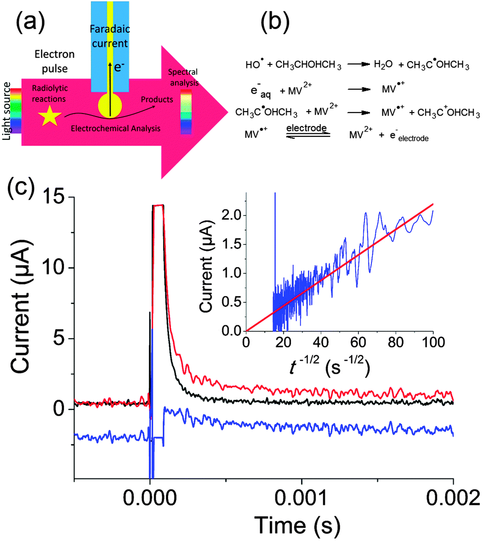 | ||
| Fig. 12 (a) Principle of electrochemical detection of intermediates created by pulse radiolysis. (b) Chemical reactions leading to production of MV˙+. (c) Transient electrochemical signal observed when a solution containing 1 mM MV2+, 0.35 M Na2SO4 and 50 mM isopropanol was irradiated with a pulse of 25 Gy. Black: parasitic signal obtained when the electrode is placed outside the beam. Red: electrochemical signal obtained when the electrode is positioned on the electron trajectory. Blue: faradaic signal obtained by subtraction (−2 μA offset was applied for clarity) Inset: I versus t−1/2 and linear fit of the faradaic signal. Adapted from ref. 88. | ||
Fig. 12c presents the transient obtained for a solution containing 1 mM methylviologen (MV2+), 0.35 M of Na2SO4 as supporting electrolyte and 50 mM of isopropanol. Isopropanol is used to scavenge OH˙ according to the scheme provided in Fig. 12b.87
MV2+ was then reduced both by the solvated electrons and by the isopropanol radical. When the cell was placed a few centimeters away from the electron beam, a large parasitic signal was obtained. In comparison to previous experiments performed with nanosecond pulses, we believe that the concentrated electron beam induces an electromagnetic destabilization of the potentiostat loop. Fortunately, this spike can be subtracted so as to recover only the faradaic signal. Since MV˙+ is a stable radical, a diffusion limited current with a t−1/2 dependence corresponding to reoxidation of MV˙+ into MV2+ was observed (cf.Fig. 12c). This allowed to determine the concentration of radicals created (1.7 × 10⁻⁵ μM), in perfect agreement with the spectroscopic measurements. This first experiment onto a well-behaved probe validated our approach.
The situation is much more complex when unstable radicals are created. In solution, bimolecular decays are then usually observed. But in addition, these unstable species may undergo oxidation and reduction at the electrode simultaneously. This is reminiscent of the observation that excited states created by light absorption are both better donor and better acceptors than the fundamental one. In electrochemistry, these systems often undergo ECE type mechanisms, the intermediate produced after the first electron transfer being unstable. In this context, in our methodology, the first electron transfer is induced by radiolysis, which allows to study the second one at potentials where the first one does not occur. With this idea but a different experimental approach, Saveant and Hapiot could already measure the redox potentials of several intermediates by ejecting electrons from the electrode with a laser pulse.88–90
Very often, electrochemical investigations in water for biological intermediates are extremely difficult to undertake. Indeed, several electrochemical and chemical steps occur, and the products formed adsorb onto the electrode for the millimolar or submillimolar concentrations often used in electrochemistry to yield sufficient current signals. The main consequence is that most of the publications concern analytical determination often using modified electrodes, but without deep study on the mechanism. On the other hand, in biological reactions the range of concentrations involved is often far below the millimolar range, which stimulated us further to explore the reactivity of biological intermediates by pulse radiolysis combined with electrochemistry.
Within this framework, we recently explored the electrochemical properties of the guanosine and guanosine monophosphate radicals (both labeled G(–H)˙ in the following) created by Br2˙−, a one electron oxidant.91 Here, the solvated electrons are quenched by N2O so as to switch to oxidative conditions and the reaction scheme follows eqn (14–18) (Scheme 2).
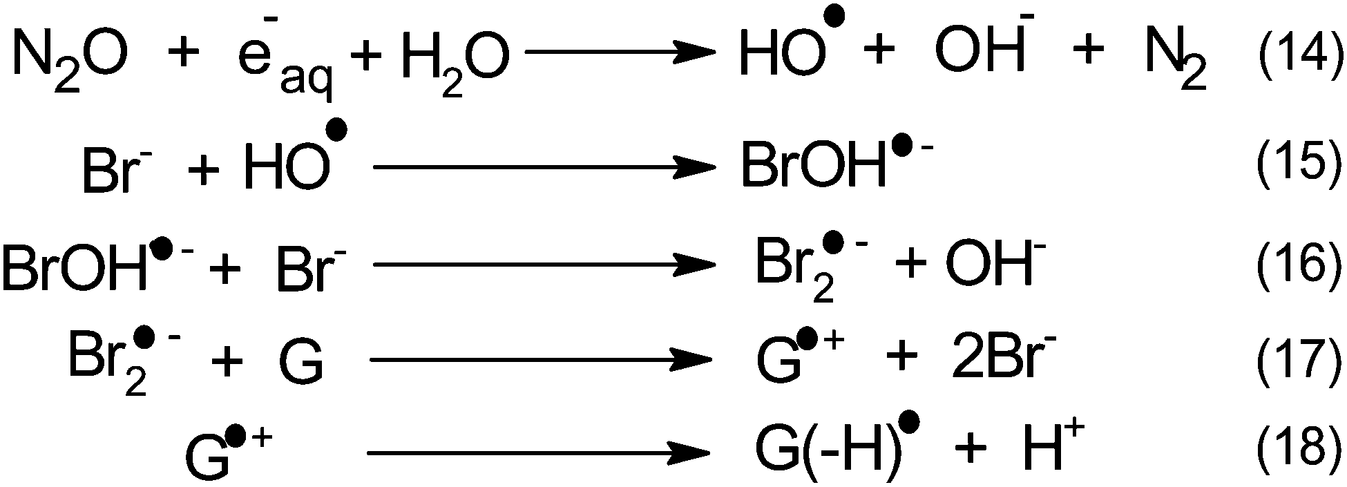 | ||
| Scheme 2 Mechanism of guanosine radical production. | ||
After 200 μs, the solution contains only G(–H)˙. Previous studies by pulse radiolysis determined an apparent redox potential of 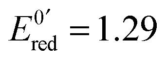 V/SHE for the system G(–H)˙/G at pH 7.92 In addition, G(–H)˙ can react with either oxidants (to probably lead to 8-oxoguanosine) or reductants (to give back G), which was termed the redox ambivalence.93
At the electrode, this ambivalence is balanced by the electrode potential, and the current transients displayed in Fig. 13 display a progressive shift from reduction to oxidation. At low potentials, the reduction predominates, so that the dimerization rate of the radical is accurately determined: kSO = 1.1 ± 0.3 × 10⁷ M−1 s−1 for guanosine monophosphate and 3 ± 1 × 10⁷ M−1 s−1 for guanosine. At intermediate potentials, the competition is regulated both by thermodynamic parameters, the standard potentials corresponding to oxidation or reduction of the radical, and by kinetic ones, the heterogeneous rate constants of these reactions. In our case, since the oxidation potential  was known from the literature, we could determine
  V/SHE. In addition, it has to be underlined that since the electrode potential was poised far from the standard potentials, we observed an effect involving a quadratic dependence of the activation energy versus the overpotential as included in the integral of eqn (7). This allowed to deduce a reorganization energy of 0.9 eV, supposed equal for oxidation or reduction.
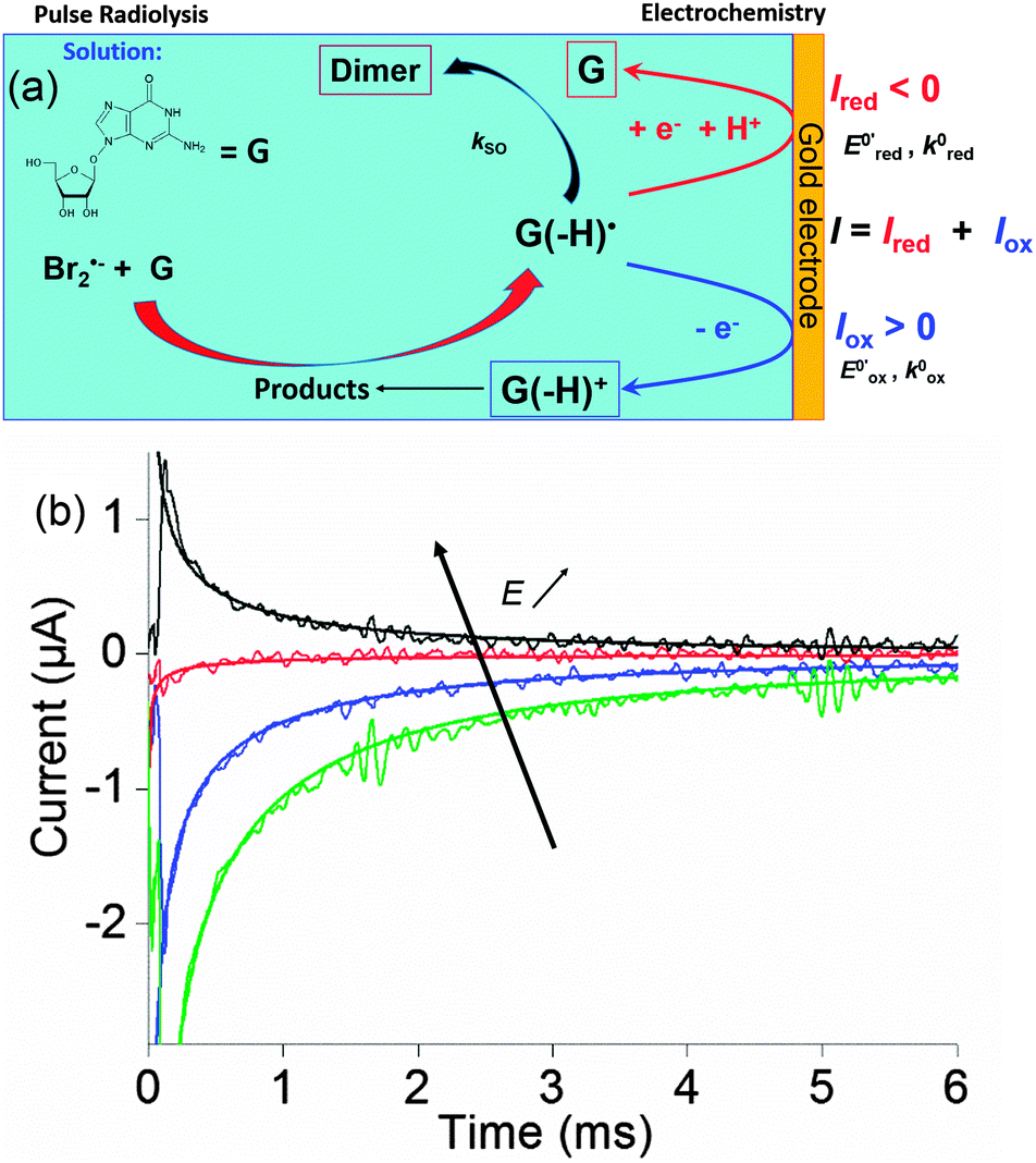 | ||
Fig. 13 (a) Scheme of guanosine or guanosinemonophosphate reactivity in solution. Reaction in solution provides a dimer while the radical may also be oxidized or reduced at the electrode surface. (b) Faradaic current transients and simulations observed for guanosinemonophosphate at 103 mV (green), 582 mV (blue), 621 mV (red) and 651 mV (black) vs. AgCl/Ag. Parameters for the simulations:  vs. AgCl/Ag, vs. AgCl/Ag, 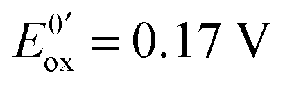 vs. AgCl/Ag, kSO = 1.1 × 10⁷ M−1 s−1, k0ox = k0red = 1 cm s−1, λox = λred = 0.9 eV. Dose 38 Gy per pulse, corresponding to an initial G(–H)˙ concentration of 28 μM. Adapted from ref. 92. vs. AgCl/Ag, kSO = 1.1 × 10⁷ M−1 s−1, k0ox = k0red = 1 cm s−1, λox = λred = 0.9 eV. Dose 38 Gy per pulse, corresponding to an initial G(–H)˙ concentration of 28 μM. Adapted from ref. 92. | ||
Here, pulse radiolysis then offered the possibility to generate micromolar concentrations of intermediate that can then undergo electron transfer at the electrode. The study of the radical is then not correlated to their production, unlike in classical electrochemical methods. Guanosine demonstrate the interest of the approach for biological systems, but the methodology will also be extended to other fields in the future.
Conclusions
The examples presented above underline the advantages of transient measurements in electrochemistry. In this respect, micrometric electrodes are required to minimize ohmic losses and provide a low time constant. Extremely rapid electron transfer in molecular wires or in macromolecules may be probed in this way, providing necessary information in view of their potential incorporation in molecular electronic devices. An ultrafast potentiostat may also be used to observe phenomena induced by a non-electrochemical perturbation. Herein, a great precision was obtained about the acoustic bubbles movements evolving a few nanometers above the electrodes. On the other hand, though heavy to implement, coupling electrochemistry with pulse radiolysis represents a powerful approach to study mechanisms in water at very low concentrations relevant to biological media.We hope that this review convinced the reader of fast electrochemistry usefulness in unravelling original systems not accessible by other methodologies.
Acknowledgements
This work was supported by ANR (project Radiolyse et Analyse Dynamique par Electrochimie, JCJC 0810), the CNRS Exchange of researchers program, the Universite Pierre et Marie Curie, the National Natural Science Foundation of China (No. 21573198 and 21273204) and Zhejiang Provincial Natural Science Foundation of China (No. LR15B030002).Notes and references
- A. J. Bard and L. R. Faulkner, Electrochemical Methods, Wiley, New York, 2001 Search PubMed.
- J.-M. Saveant, Elements Molecular and Biomolecular Electrochemistry, John Wiley and Son, Hoboken, New Jersey, 1st edn, 2006 Search PubMed.
- N. V. Rees, O. V. Klymenko, E. Maisonhaute, B. A. Coles and R. G. Compton, J. Electroanal. Chem., 2003, 542, 23–32 CrossRef CAS.
- J. J. Watkins, J. Y. Chen, H. S. White, H. D. Abruna, E. Maisonhaute and C. Amatore, Anal. Chem., 2003, 75, 3962–3971 CrossRef CAS PubMed.
- Scanning Electrochemical Microscopy, ed. A. J. Bard and M. V. Mirkin, Taylor & Francis, Boca Raton, FL, 2nd edn, 2012 Search PubMed.
- F. R. F. Fan and A. J. Bard, Science, 1995, 267, 871–874 CrossRef CAS PubMed.
- R. Forster and L. Faulkner, J. Am. Chem. Soc., 1994, 116, 5453–5461 CrossRef CAS.
- N. V. Rees, C. E. Banks and R. G. Compton, J. Phys. Chem. B, 2004, 108, 18391–18394 CrossRef CAS.
- M. E. Orazem and B. Tribollet, Electrochemical Impedance Spectroscopy, John Wiley & Sons, Hoboken, New Jersey, 2008 Search PubMed.
- C. Amatore and E. Maisonhaute, Anal. Chem., 2005, 77, 303A–311A CrossRef CAS PubMed.
- C. Amatore, S. Arbault, E. Maisonhaute, S. Szunerits and L. Thouin, in Trends In Molecular Electrochemistry, ed. J. L. Pombeiro and C. Amatore, Fontis Media, Lausanne, 2004, pp. 385–411 Search PubMed.
- C. Amatore, C. Lefrou and F. Pfluger, J. Electroanal. Chem., 1989, 270, 43–59 CrossRef CAS.
- C. Amatore and C. Lefrou, J. Electroanal. Chem., 1992, 324, 33–58 CrossRef CAS.
- C. P. Andrieux, D. Garreau, P. Hapiot and J. M. Saveant, J. Electroanal. Chem., 1988, 248, 447–450 CrossRef CAS.
- C. P. Andrieux, P. Hapiot and J. M. Saveant, Electroanalysis, 1990, 2, 183–193 CrossRef CAS.
- D. Garreau, P. Hapiot and J. M. Saveant, J. Electroanal. Chem., 1990, 281, 73–83 CrossRef CAS.
- R. M. Wightman and D. O. Wipf, Acc. Chem. Res., 1990, 23, 64–70 CrossRef CAS.
- D. O. Wipf and R. M. Wightman, Anal. Chem., 1988, 60, 2460–2464 CrossRef CAS.
- D. O. Wipf, E. W. Kristensen, M. R. Deakin and R. M. Wightman, Anal. Chem., 1988, 60, 306–310 CrossRef CAS.
- C. Amatore, E. Maisonhaute and G. Simonneau, J. Electroanal. Chem., 2000, 486, 141–155 CrossRef CAS.
- C. Amatore, E. Maisonhaute and G. Simonneau, Electrochem. Commun., 2000, 2, 81–84 CrossRef CAS.
- P. Fortgang, C. Amatore, E. Maisonhaute and B. Schollhorn, Electrochem. Commun., 2010, 12, 897–900 CrossRef CAS.
- C. Arrigoni, G. Schull, D. Bleger, L. Douillard, C. Fiorini-Debuisschert, F. Mathevet, D. Kreher, A. J. Attias and F. Charra, J. Phys. Chem. Lett., 2010, 1, 190–194 CrossRef CAS.
- P. Aubertin, M. Aissa, N. Raouafi, S. Joiret, A. Courty and E. Maisonhaute, Nano Res., 2015, 8, 1615–1626 CrossRef CAS.
- S. S. Isied, M. Y. Ogawa and J. F. Wishart, Chem. Rev., 1992, 92, 381–394 CrossRef CAS.
- J. C. Genereux and J. K. Barton, Chem. Rev., 2010, 110, 1642–1662 CrossRef CAS PubMed.
- D. M. Adams, L. Brus, C. E. D. Chidsey, S. Creager, C. Creutz, C. R. Kagan, P. V. Kamat, M. Lieberman, S. Lindsay, R. A. Marcus, R. M. Metzger, M. E. Michel-Beyerle, J. R. Miller, M. D. Newton, D. R. Rolison, O. Sankey, K. S. Schanze, J. Yardley and X. Y. Zhu, J. Phys. Chem. B, 2003, 107, 6668–6697 CrossRef CAS.
- R. A. Marcus, J. Chem. Phys., 1965, 43, 679 CrossRef CAS.
- C. E. D. Chidsey, Science, 1991, 251, 919–922 CrossRef CAS PubMed.
- E. Laborda, M. C. Henstridge, C. Batchelor-McAuley and R. G. Compton, Chem. Soc. Rev., 2013, 42, 4894–4905 RSC.
- H. D. Sikes, J. F. Smalley, S. P. Dudek, A. R. Cook, M. D. Newton, C. E. D. Chidsey and S. W. Feldberg, Science, 2001, 291, 1519–1523 CrossRef CAS PubMed.
- R. J. Nichols, W. Haiss, S. J. Higgins, E. Leary, S. Martin and D. Bethell, Phys. Chem. Chem. Phys., 2010, 12, 2801–2815 RSC.
- B. Q. Xu and N. J. Tao, Science, 2003, 301, 1221–1223 CrossRef CAS PubMed.
- W. Haiss, T. Albrecht, H. van Zalinge, S. J. Higgins, D. Bethell, H. Hobenreich, D. J. Schiffrin, R. J. Nichols, A. M. Kuznetsov, J. Zhang, Q. Chi and J. Ulstrup, J. Phys. Chem. B, 2007, 111, 6703–6712 CrossRef CAS PubMed.
- B. Q. Xu, X. Y. Xiao, X. M. Yang, L. Zang and N. J. Tao, J. Am. Chem. Soc., 2005, 127, 2386–2387 CrossRef CAS PubMed.
- D.-F. Li, J.-C. Mao, D.-L. Chen, F. Chen, H. Ze-Wen, X.-Y. Zhou, Y.-H. Wang, X.-S. Zhou, Z.-J. Niu and E. Maisonhaute, Electrochim. Acta, 2015, 174, 340–344 CrossRef CAS.
- L. Venkataraman, J. E. Klare, C. Nuckolls, M. S. Hybertsen and M. L. Steigerwald, Nature, 2006, 442, 904–907 CrossRef CAS PubMed.
- M. C. Traub, B. S. Brunschwig and N. S. Lewis, J. Phys. Chem. B, 2007, 111, 6676–6683 CrossRef CAS PubMed.
- A. Nitzan, J. Phys. Chem. A, 2001, 105, 2677–2679 CrossRef CAS.
- A. Migliore and A. Nitzan, Electrochim. Acta, 2015, 160, 363–375 CrossRef CAS.
- T. Albrecht, K. Moth-Poulsen, J. B. Christensen, A. Guckian, T. Bjornholm, J. G. Vos and J. Ulstrup, Faraday Discuss., 2006, 131, 265–279 RSC.
- J. Zhang, A. M. Kuznetsov, I. G. Medvedev, Q. Chi, T. Albrecht, P. S. Jensen and J. Ulstrup, Chem. Rev., 2008, 108, 2737–2791 CrossRef CAS PubMed.
- E. Leary, S. J. Higgins, H. van Zalinge, W. Haiss, R. J. Nichols, S. Nygaard, J. O. Jeppesen and J. Ulstrup, J. Am. Chem. Soc., 2008, 130, 12204–12205 CrossRef CAS PubMed.
- N. J. Kay, S. J. Higgins, J. O. Jeppesen, E. Leary, J. Lycoops, J. Ulstrup and R. J. Nichols, J. Am. Chem. Soc., 2012, 134, 16817–16826 CrossRef CAS PubMed.
- X. S. Zhou, L. Liu, P. Fortgang, A. S. Lefevre, A. Serra-Muns, N. Raouafi, C. Amatore, B. W. Mao, E. Maisonhaute and B. Schollhorn, J. Am. Chem. Soc., 2011, 133, 7509–7516 CrossRef CAS PubMed.
- X. L. Li, J. He, J. Hihath, B. Q. Xu, S. M. Lindsay and N. J. Tao, J. Am. Chem. Soc., 2006, 128, 2135–2141 CrossRef CAS PubMed.
- W. Haiss, S. Martin, E. Leary, H. van Zalinge, S. J. Higgins, L. Bouffier and R. J. Nichols, J. Phys. Chem. C, 2009, 113, 5823–5833 CAS.
- C. Li, I. Pobelov, T. Wandlowski, A. Bagrets, A. Arnold and F. Evers, J. Am. Chem. Soc., 2008, 130, 318–326 CrossRef CAS PubMed.
- J. H. Tian, Y. Yang, X. S. Zhou, B. Schollhorn, E. Maisonhaute, Z. B. Chen, F. Z. Yang, Y. Chen, C. Amatore, B. W. Mao and Z. Q. Tian, ChemPhysChem, 2010, 11, 2745–2755 CrossRef CAS PubMed.
- C. Amatore, E. Maisonhaute, B. Schollhorn and J. Wadhawan, ChemPhysChem, 2007, 8, 1321–1329 CrossRef CAS PubMed.
- W. Haiss, H. van Zalinge, D. Bethell, J. Ulstrup, D. J. Schiffrin and R. J. Nichols, Faraday Discuss., 2006, 131, 253–264 RSC.
- M. Kamenetska, S. Y. Quek, A. C. Whalley, M. L. Steigerwald, H. J. Choi, S. G. Louie, C. Nuckolls, M. S. Hybertsen, J. B. Neaton and L. Venkataraman, J. Am. Chem. Soc., 2010, 132, 6817–6821 CrossRef CAS PubMed.
- C. Leger and P. Bertrand, Chem. Rev., 2008, 108, 2379–2438 CrossRef CAS PubMed.
- B. Giese, Annu. Rev. Biochem., 2002, 71, 51–70 CrossRef CAS PubMed.
- H. Dahms, J. Phys. Chem., 1968, 72, 362 CrossRef CAS.
- I. Ruff and I. Korosiod, Inorg. Chem., 1970, 9, 186 CrossRef CAS.
- D. N. Blauch and J. M. Saveant, J. Am. Chem. Soc., 1992, 114, 3323–3332 CrossRef CAS.
- C. Amatore, Y. Bouret, E. Maisonhaute, J. I. Goldsmith and H. D. Abruna, ChemPhysChem, 2001, 2, 130–134 CrossRef CAS PubMed.
- C. Amatore, Y. Bouret, E. Maisonhaute, J. I. Goldsmith and H. D. Abruna, Chem. – Eur. J., 2001, 7, 2206–2226 CrossRef CAS.
- J. A. Camerano, M. A. Casado, U. Hahn, J. F. Nierengarten, E. Maisonhaute and C. Amatore, New J. Chem., 2007, 31, 1395–1399 RSC.
- U. Hahn, E. Maisonhaute, C. Amatore and J. F. Nierengarten, Angew. Chem., Int. Ed., 2007, 46, 951–954 CrossRef CAS PubMed.
- P. Fortgang, E. Maisonhaute, C. Amatore, B. Delavaux-Nicot, J. Iehl and J. F. Nierengarten, Angew. Chem., Int. Ed., 2011, 50, 2364–2367 CrossRef CAS PubMed.
- C. Amatore, F. Grun and E. Maisonhaute, Angew. Chem., Int. Ed., 2003, 42, 4944–4947 CrossRef CAS PubMed.
- M. Erard, A. Fredj, H. Pasquier, D. B. Beltolngar, Y. Bousmah, V. Derrien, P. Vincent and F. Merola, Mol. BioSyst., 2013, 9, 258–267 RSC.
- F. Merola, A. Fredj, D. B. Betolngar, C. Ziegler, M. Erard and H. Pasquier, Biotechnol. J., 2014, 9, 180–191 CrossRef CAS PubMed.
- R. G. Compton, F. Marken and T. O. Rebbitt, Chem. Commun., 1996, 1017–1018 RSC.
- E. Maisonhaute, P. C. White and R. G. Compton, J. Phys. Chem. B, 2001, 105, 12087–12091 CrossRef CAS.
- E. Maisonhaute, B. A. Brookes and R. G. Compton, J. Phys. Chem. B, 2002, 106, 3166–3172 CrossRef CAS.
- E. Maisonhaute, F. J. Del Campo and R. G. Compton, Ultrason. Sonochem., 2002, 9, 275–283 CrossRef CAS PubMed.
- E. Maisonhaute, C. Prado, P. C. White and R. G. Compton, Ultrason. Sonochem., 2002, 9, 297–303 CrossRef CAS PubMed.
- F. J. Del Campo, E. Maisonhaute, R. G. Compton, F. Marken and A. Aldaz, J. Electroanal. Chem., 2001, 506, 170–177 CrossRef CAS.
- R. G. Compton, J. C. Eklund and F. Marken, Electroanalysis, 1997, 9, 509–522 CrossRef CAS.
- L. A. Crum, J. Phys., 1979, 11, C8–285 Search PubMed.
- A. Philipp and W. Lauterborn, J. Fluid Mech., 1998, 361, 75–116 CrossRef CAS.
- P. R. Birkin and S. SilvaMartinez, J. Electroanal. Chem., 1996, 416, 127–138 CrossRef CAS.
- P. R. Birkin, D. G. Offin and T. G. Leighton, Electrochem. Commun., 2004, 6, 1174–1179 CrossRef CAS.
- T. G. Leighton, Ultrasonics, 1989, 27, 50–53 CrossRef.
- T. G. Leighton, The Acoustic Bubble, Academic Press, 1994 Search PubMed.
- T. G. Leighton, A. J. Walton and J. E. Field, Ultrasonics, 1989, 27, 370–373 CrossRef.
- C. Amatore, G. Farsang, E. Maisonhaute and P. Simon, J. Electroanal. Chem., 1999, 462, 55–62 CrossRef CAS.
- A. Et Taouil, E. Brun, P. Duchambon, Y. Blouquit, M. Gilles, E. Maisonhaute and C. Sicard-Roselli, Phys. Chem. Chem. Phys., 2014, 16, 24493–24498 RSC.
- P. Wardman and A. B. Ross, Free Radical Biol. Med., 1991, 10, 243–247 CrossRef CAS PubMed.
- E. Sutter, K. Jungjohann, S. Bliznakov, A. Courty, E. Maisonhaute, S. Tenney and P. Sutter, Nat. Commun., 2014, 5, 4946 CrossRef CAS PubMed.
- J. L. Marignier, V. de Waele, H. Monard, F. Gobert, J. P. Larbre, A. Demarque, M. Mostafavi and J. Belloni, Radiat. Phys. Chem., 2006, 75, 1024–1033 CrossRef CAS.
- A. Balcerzyk, U. Schmidhammer, G. Horne, F. Wang, J. Ma, S. M. Pimblott, A. de la Lande and M. Mostafavi, J. Phys. Chem. B, 2015, 119, 10096–10101 CrossRef CAS PubMed.
- A. Henglein, in Electroanalytical Chemistry – A Series of Advances, ed. A. J. Bard, Marcel Dekker, New York, 1976, vol. 9, pp. 163–245 Search PubMed.
- M. S. Alam, E. Maisonhaute, D. Rose, A. Demarque, J. P. Larbre, J. L. Marignier and M. Mostafavi, Electrochem. Commun., 2013, 35, 149–151 CrossRef CAS.
- J. Gonzalez, P. Hapiot, V. Konovalov and J. M. Saveant, J. Electroanal. Chem., 1999, 463, 157–189 CrossRef CAS.
- P. F. Hapiot, L. D. Kispert, V. V. Konovalov and J. M. Saveant, J. Am. Chem. Soc., 2001, 123, 6669–6677 CrossRef CAS PubMed.
- C. P. Andrieux, J. Gamby, P. Hapiot and J. M. Saveant, J. Am. Chem. Soc., 2003, 125, 10119–10124 CrossRef CAS PubMed.
- A. Latus, M. S. Alam, M. Mostafavi, J. L. Marignier and E. Maisonhaute, Chem. Commun., 2015, 51, 9089–9092 RSC.
- S. Steenken and S. V. Jovanovic, J. Am. Chem. Soc., 1997, 119, 617–618 CrossRef CAS.
- P. O'Neill and P. W. Chapman, Int. J. Radiat. Biol., 1985, 47, 71–80 CrossRef.
| This journal is © The Royal Society of Chemistry 2016 |