 Open Access Article
Creative Commons Attribution 3.0 Unported Licence
Cholesteric films exhibiting expanded or split reflection bands prepared by atmospheric photopolymerisation of diacrylic nematic monomer doped with a photoresponsive chiral dopant
Y.
Harada
,
K.
Sakajiri
,
H.
Kuwahara
,
S.
Kang
,
J.
Watanabe
and
M.
Tokita
*
Department of Organic and Polymeric Materials, Tokyo Institute of Technology, Ookayama, Meguro-ku, Tokyo 152-8552, Japan. E-mail: mtokita@polymer.titech.ac.jp
First published on 2nd March 2015
Abstract
Cholesteric liquid crystal (CLC) films with gradient pitches are prepared by atmospheric UV irradiation of mixtures of a diacrylic nematic monomer (M), a macrocyclised chiral cinnamate dimer (CD), and a photoinitiator (PI). UV light induces the intramolecular photodimerisation of the two cinnamate moieties in the CD to decrease the helical twisting power. The CLC of 90/10 (w/w) mixture of M/CD exhibits an optical pitch of 482 nm, which increases homogeneously to 815 nm upon atmospheric UV irradiation of the film. When the CLC doped with 1.5 wt% PI is formed into a planar-aligned film and irradiated with UV light in the atmosphere, the CLC film exhibits pitches that increases toward the air-interface side so as to result in a wide reflection band ranging from 420 to 890 nm; in addition, the film assumes a silver appearance. When the PI concentration and UV intensity are increased, the spectra of the CLC films exhibit two reflection bands and films assume a magenta colour. Such pitch distributions result from the confliction between untwisting and polymerisation of the CLC, both of which are induced by the UV light, although the polymerisation rate is decreased by the diffusion of atmospheric oxygen into the film.
Introduction
Cholesteric liquid crystals (CLCs) consist of molecules whose orientation varies in a helical fashion with a twist axis perpendicular to the local director. At normal incidence, they reflect circularly polarised incident light of the same handedness as the cholesteric helix and of wavelength λ between noP and neP, where no and ne are the ordinary and extraordinary refractive indices, respectively, of the locally uniaxial structure and P is the pitch of the helix. Thus, the reflection bandwidth Δλ is given by Δλ = ΔnP, where Δn = ne − no is the birefringence. Because Δn is typically limited to 0.3–0.4 for colorless organic compounds, CLCs typically exhibit a Δλ of less than 150 nm in the visible spectrum. Although a narrow reflection band is desirable for applications such as optical filters and thermal imaging,1–4 it becomes a drawback in other applications, such as reflective displays, broadband circular polarizers, and switchable mirrors.5–8One of the subtle approaches to enlarging the reflection band of CLCs is the formation of a pitch gradient.9 Gradients in the pitch have been created by the following three methods. The first method is annealing two CLC films with long and short pitches in tight contact.10 A continuous pitch gradient is formed between the two original films because of thermal diffusion of the LC molecules. The second method is the effective utilization of photoracemisation11 or photoisomerisation12 of chiral dopants. Photoracemization converts the (R)-enantiomer of a dopant near the UV-irradiated CLC film surface to the corresponding (S)-enantiomer. The enantiomers diffuse mutually across the film to generate a pitch gradient. The photoisomerisation of chiral dopant increases/decreases the helical twisting power (HTP). When a CLC is doped with a UV absorber, the isomerisation at the lamp side of the film proceeds faster than that at the opposite site. Thus, the film possesses a pitch gradient after a certain period of UV exposure. The third method is photopolymerisation of a planar-oriented CLC film of a mixture of cholesteric diacrylate monomer and nematic monoacrylate monomer in the presence of a photoinitiator (PI).6–8,13 Whereas the more reactive diacrylic chiral monomer polymerise preferentially, the nematic acrylate monomer diffuse toward the sides opposite the irradiated surface. Thus, the concentration gradient of the helix-winding chiral material is produced and the pitch varies continuously over the film thickness. The Δλ of the film is increased, and the reflection band can be broadened over the entire visible spectrum.
In this paper, we demonstrate that gradient-pitch CLC films can be prepared by atmospheric UV-light irradiation on a planar-aligned CLC of a mixture of a diacrylic nematic monomer and a photoreactive chiral cinnamate dimer in the presence of a PI. UV light causes the intramolecular photodimerisation of the two cinnamate moieties in the dimer to decrease the HTP, and it simultaneously induces polymerisation of the nematic diacrylate monomer via a free-radical cross-linking mechanism and fixes the conformation of the LC phase. As oxygen diffusing into the film decreases the radical polymerisation rate, competition between the rates of monomer polymerisation and the chiral dopant photoreaction makes the pitch increase continuously from the glass-substrate side to the air-interface side. The deposited CLC film exhibited a wide reflection bandwidth to assume a silver color. Moreover, with increasing UV intensity and PI concentration, two reflection bands formed in the CLC film, which assumed a magenta colour.
Experimental
Materials
The diacrylate nematic liquid crystal (NLC) monomer LC242 (BASF) and the radical polymerisation PI Irg907 (BASF) were used. The chiral dopant C8-4-2Me was synthesized using methods similar to that described in the literature.14 The structure formulas of these chemicals are shown in Fig. 1.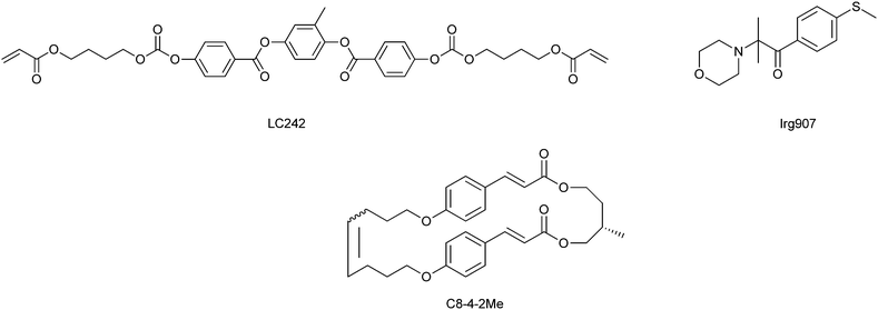 | ||
| Fig. 1 Chemical structures of the mesogenic compound (LC242), the photoinitiator (PI), and the photoreactive chiral dopant (C8-4-2Me). | ||
Fig. 2 outlines the synthetic route leading to C8-4-2Me. A mixture of 3-(4-hydroxyphenyl)acrylic acid (1.64 g, 10 mmol), 5-bromopent-1-ene (2.24 g, 15 mmol), potassium hydroxide (KOH) (1.12 g, 20 mmol), potassium iodide (KI) (0.58 g, 5 mmol), ethanol (EtOH) (60 ml), and water (20 ml) was refluxed for 24 h. The solution was cooled and poured into 400 ml of water and the resulting precipitate was collected by filtration and washed with water. The crude product was recrystallised from ethanol to give 1 (2.23 g, 96%) as a white solid. 1H-NMR (400 MHz, CDCl3): δ = 7.75 (1H, d, J = 15.8 Hz, Ar-CH), 7.50 (2H, d, J = 8.8 Hz, Ar-H), 6.91 (2H, d, J = 8.8 Hz, Ar-H), 6.32 (1H, d, J = 15.8 Hz, CO-CH), 5.90–5.80 (1H, m, CH2CH), 5.10–5.04 (1H, m, ![[double bond, length as m-dash]](https://www.rsc.org/images/entities/char_e001.gif) CH2), 5.03–5.00 (1H, m,
CH2), 5.03–5.00 (1H, m, ![[double bond, length as m-dash]](https://www.rsc.org/images/entities/char_e001.gif) CH2), 4.02 (2H, t, J = 6.6 Hz, OCH2), 2.25 (2H, m,
CH2), 4.02 (2H, t, J = 6.6 Hz, OCH2), 2.25 (2H, m, ![[double bond, length as m-dash]](https://www.rsc.org/images/entities/char_e001.gif) CHCH2), 1.91 (2H, m, CH2CH2CH2).
CHCH2), 1.91 (2H, m, CH2CH2CH2).
A mixture of 1 (3.48 g, 15 mmol), (S)-2-methylbutane-1,4-diol (0.52 g, 5.0 mmol), 1-ethyl-3-(3-dimethylaminopropyl)carbodiimide (EDCI) (3.8 g, 20 mmol), N,N-dimethyl-4-aminopyridine (DMAP) (0.24 g, 2.0 mmol) and dichloromethane (CH2Cl2) (100 ml) was stirred at r.t. for 12 h. The solvent was removed under reduced pressure and poured into methanol. The precipitate was collected by filtration and recrystallised from a mixed solvent of chloroform (CHCl3) and EtOH to give 2 (2.56 g, 96%) as a white solid. 1H NMR (400 MHz, CDCl3): δ = 7.64 (2H, d, J = 15.8 Hz, Ar-CH), 7.47–7.44 (4H, m, Ar-H), 6.88 (4H, d, J = 8.5 Hz, Ar-H,), 6.34–6.28 (2H, m, O![[double bond, length as m-dash]](https://www.rsc.org/images/entities/char_e001.gif) CCH), 5.90–5.80 (2H, m, CH2
CCH), 5.90–5.80 (2H, m, CH2![[double bond, length as m-dash]](https://www.rsc.org/images/entities/char_e001.gif) CH), 5.09–5.00 (4H, m,
CH), 5.09–5.00 (4H, m, ![[double bond, length as m-dash]](https://www.rsc.org/images/entities/char_e001.gif) CH2), 4.35–4.24 (2H, m, OCH2CH(CH3)), 4.11–4.10 (2H, m, CH2CH2CH(CH3)), 3.99 (4H, t, J = 6.6 Hz, J = 6.3 Hz, ArOCH2), 2.27–2.22 (4H, m,
CH2), 4.35–4.24 (2H, m, OCH2CH(CH3)), 4.11–4.10 (2H, m, CH2CH2CH(CH3)), 3.99 (4H, t, J = 6.6 Hz, J = 6.3 Hz, ArOCH2), 2.27–2.22 (4H, m, ![[double bond, length as m-dash]](https://www.rsc.org/images/entities/char_e001.gif) CHCH2), 2.12–2.04 (2H, m, CH(CH3)CH2CH2), 1.93–1.86 (4H, m, CH2CH2CH2), 1.67–1.58 (1H, m, CH3CH), 1.06 (3H, d, J = 6.8 Hz, CH3).
CHCH2), 2.12–2.04 (2H, m, CH(CH3)CH2CH2), 1.93–1.86 (4H, m, CH2CH2CH2), 1.67–1.58 (1H, m, CH3CH), 1.06 (3H, d, J = 6.8 Hz, CH3).
A mixture of 2 (1.07 g, 2.0 mmol), first-generation Grubbs catalyst (0.33 g, 0.40 mmol) and dry CH2Cl2 (2.0 L) was stirred at r.t. for 3 d. The solvent was removed under reduced pressure. The residue was purified by alumina column chromatography with CH2Cl2 as the eluent and by recycle HPLC and was subsequently recrystallised from a mixed solvent of CHCl3–MeOH to give C8-4-2Me (3, 1.01 g, 65%) as a white solid. 1H NMR (400 MHz, CDCl3): δ = 7.58–7.48 (2H, m, Ar-CH), 7.25–7.18 (4H, m, Ar-H), 6.67–6.57 (4H, m, Ar-H), 6.25–6.17 (2H, m, O![[double bond, length as m-dash]](https://www.rsc.org/images/entities/char_e001.gif) CCH), 5.45–5.38 (2H, m, CH
CCH), 5.45–5.38 (2H, m, CH![[double bond, length as m-dash]](https://www.rsc.org/images/entities/char_e001.gif) CH), 4.46–4.41(1H, m, OCH2CH(CH3)), 4.35–4.31(1H, m, CH2CH2CH(CH3)), 4.20–4.14 (1H, m, CH2CH2CH(CH3)), 3.89–3.80 (4H + 1H, m, ArOCH2, OCH2CH(CH3)), 2.29–2.17 (4H, m,
CH), 4.46–4.41(1H, m, OCH2CH(CH3)), 4.35–4.31(1H, m, CH2CH2CH(CH3)), 4.20–4.14 (1H, m, CH2CH2CH(CH3)), 3.89–3.80 (4H + 1H, m, ArOCH2, OCH2CH(CH3)), 2.29–2.17 (4H, m, ![[double bond, length as m-dash]](https://www.rsc.org/images/entities/char_e001.gif) CHCH2), 2.14–2.06 (1H, m, CH(CH3)CH2CH2), 1.97–1.82 (4H + 1H, m,
CHCH2), 2.14–2.06 (1H, m, CH(CH3)CH2CH2), 1.97–1.82 (4H + 1H, m, ![[double bond, length as m-dash]](https://www.rsc.org/images/entities/char_e001.gif) CHCH2CH2, CH(CH3)CH2CH2,), 1.67–1.62 (1H, m, CH3CH), 1.03 (3H, d, J = 6.84 Hz, CH3). 3 was obtained as a mixture of the cis and trans isomers, however, the accurate isomer ratio was hardly estimated by the NMR spectrum showing peaks of each isomer overlapping with each other. MS(MALDI-TOF) for C31H36O6: 527.19 (M + Na+).
CHCH2CH2, CH(CH3)CH2CH2,), 1.67–1.62 (1H, m, CH3CH), 1.03 (3H, d, J = 6.84 Hz, CH3). 3 was obtained as a mixture of the cis and trans isomers, however, the accurate isomer ratio was hardly estimated by the NMR spectrum showing peaks of each isomer overlapping with each other. MS(MALDI-TOF) for C31H36O6: 527.19 (M + Na+).
LC film preparation
Planar-aligned CLC films with a thickness of 20 μm were prepared by spreading a CLC solution in chloroform at a concentration of 10 wt% onto a rubbed polyimide-coated glass. The LC films were irradiated with UV light from the air-interface side using an Ushio Spot UV curing SP-9 (λmax = 365 nm) light source equipped with band-pass filter (365 nm). The film temperature was controlled using a Mettler FP90/82HT hotstage.Physical measurements
Transmission spectra were measured on a Nikon lv100 POL polarising optical microscope equipped with an Ocean Optics USB4000 spectroscope. To measure the transmission of circularly polarised light, an achromatic λ/4 film was inserted between the CLC film and the polarizer. The reflection was measured as transmission loss. Scanning electron microscopy (SEM) was performed on a JEOL JSM-7000F microscope.Results and discussion
CLCs were prepared by doping LC242 with C8-4-2Me. C8-4-2Me is a macrocyclised chiral dimer consisting of two photoreactive cinnamate moieties that are linked to each other by a flexible spacer with a chiral carbon on one side and an alkyl spacer on the other side. UV irradiation of macrocyclised chiral cinnamate dimers induced intramolecular [2+2] dimerisation of the cinnamate groups to decrease the HTP.14 Though C8-4-2Me in the LC242 nematic LC exhibited the HTP of 21 μm−1 wt%−1, the HTP of the photoreacted C8-4-2Me measured for a sample recovered after complete photodimerisation in solution was 0 μm−1 wt%−1. A 90/10 (w/w) mixture of LC242/C8-4-2Me formed a CLC. Fig. 3a shows the transmission spectra of the resulting CLC films with a thickness 20 μm under irradiation with UV light (10 mW cm−2, λmax = 365 nm) for periods ranging from 0 to 150 s. The film temperature was maintained at 70 °C during the UV irradiation and the spectrum measurements. Before UV irradiation, the CLC film exhibited a reflection band with a center wavelength λ0 = 482 nm. When the UV irradiation period was increased to 150 s, the λ0 increased to 815 nm. In Fig. 3b, the long- and short-edge wavelengths (λL and λS, respectively) are plotted against the irradiation time. Here the reflection band edge wavelengths are defined as the wavelengths at half-maxima. Both λL and λS increased linearly with increasing irradiation period, although the peak widths, Δλ, doubled; this result was as expected on the basis of the increase in P being similar to that reported for a CLC of a mixture of a chiral cinnamate dimer and an inactive NLC.14 Thus, the UV light passes through the film and decreases the HTP of the C8-4-2Me chiral dopant so as to increase P homogeneously.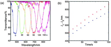 | ||
| Fig. 3 Effects of UV-irradiation time on the (a) transmission spectrum and the (b) reflection band edge wavelengths for the chiral nematic liquid crystal of a 90/10 (w/w) mixture of LC242/C8-4-2Me. | ||
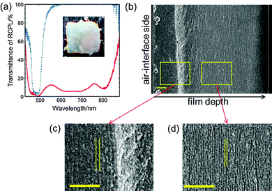
When the CLC was doped with Irg907, UV irradiation induced the polymerisation of LC242 as well as the photoreaction of C8-4-2Me. Here, PI-doped CLC of a (90 − x)/10/x (w/w/w) mixture of LC242, C8-4-2Me and Irg907 is designated as CLC-x. Fig. 4a shows the transmission spectrum of the CLC-2.5 films subjected to UV irradiation for periods up to 150 s. The spectrum of the film before UV irradiation exhibited a reflection band with λ0 = 485 nm and Δλ = 59 nm. After the film was subjected to UV irradiation, the reflection band expanded significantly. The λL and λS of the PI-containing CLC film are plotted against the irradiation time in Fig. 4b. Whereas λS decreased slightly from 455 nm to 444 nm, λL increased significantly from 515 nm to 652 nm, and Δλ increased to 208 nm. When x was decreased to 1.5 wt% and the UV irradiation period was prolonged to 300 s to ensure vitrification of the film, λL increased from 513 to 871 nm, whereas λS decreased slightly from 457 to 432 nm (Fig. 5a). The spectrum of the UV-irradiated CLC-1.5 film exhibited a wide reflection band ranging from 420 to 890 nm and the film itself exhibited a silver sheen, as shown in the inset photograph in Fig. 5a. UV-irradiated CLC-x films with x less than 1 wt% exhibited a sticky surface even after prolonged UV irradiation.
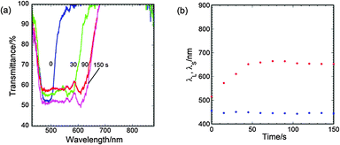 | ||
| Fig. 4 Effects of UV-irradiation time on the (a) transmission spectrum and (b) reflection band edge wavelengths for CLC-2.5. The UV light intensity was 10 mW cm−2. | ||
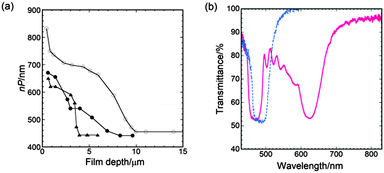
The broadening of the reflection band of CLC-x films by UV irradiation is attributed to the formation of a pitch gradient in the film thickness direction. The scanning electron microscopy (SEM) image of the cross-section of the UV-irradiated CLC-1.5 film shown in Fig. 5b includes numerous lines parallel to the film direction. Two areas in the SEM image at different film depths are magnified and shown in Fig. 5c and d. The line spacing decreases from 275 to 150 nm from the air-interface side to the glass-substrate side. Because this line spacing corresponds to half of P, it indicates that P decreases from 550 nm at the interface with air to 300 nm at a film depth of 10 μm. The optical pitch nP is plotted against film depth as open circles in Fig. 6a under the assumption that the refractive index of the CLC is a typical value of 1.5. The nP decreases in two stages with increasing film depth (i.e., the distance from the air surface) to a depth of 10 μm. The nP decreases from 830 to 700 nm and from 700 to 450 nm at film depths ranging from 0 to 2 μm and from 5 to 10 μm, respectively, whereas nP is constant at film depths between 2 to 5 μm and greater than 10 μm. Such a variation of nP appears to correspond to the reflection spectrum. The wide reflection band of CLC-1.5 has two hollows at 550 and 760 nm and can be divided into two narrower bands (λ0 = 475 and 805 nm) and one wider band (λ0 = 655 nm). The wider band is associated with the second nP decrease at film depths ranging from 5 to 10 μm.
The gradating cholesteric pitch formation can result from a conflict between helix untwisting and the polymerisation of the diacrylate monomer in the CLC, both of which are induced by UV light. UV light induces the photoreaction of the chiral dopant, which decreases the HTP to untwist the CLC; however, it also induces polymerisation of the diacyclic monomer to prevent the CLC from changing conformation, such as by untwisting. The P at film depth greater than 10 μm is approximately the same as that in the non-UV-irradiated film, indicating that the CLC vitrifies so quickly that it cannot untwist even though the HTP of the chiral dopant decreases. In the upper half of the film, the pitch increases toward the air-interface side, suggesting that the CLC vitrified after partial unwinding of the CLC helix. The gradual pitch increment indicates that the polymerisation rate slows toward the air-interface side. Such a variation of the polymerisation rate in UV-irradiated CLC films is expected if atmospheric oxygen is dissolved in the CLC and diffuses into the film during UV irradiation. Although oxygen dissolved in the CLC reacts with radicals generated by the UV-illuminated PI, unconsumed radicals can initiate the polymerisation. The P at film depth greater than 10 μm is not changed upon UV irradiation, even though the chiral dopant decreases the HTP via the photoreaction. This result suggests that the concentration of unconsumed radical is sufficiently high that the polymerisation rate is sufficiently rapid to maintain the original CLC configuration. In contrast, in the upper half of the film, the pitch increases with decreasing film depth, suggesting that the polymerisation rate decreases with decreasing film depth to allow the CLC to untwist. This behaviour is explainable if oxygen permeates into the film from the air interface. Radicals generated from UV-irradiated PI will react with permeated oxygen such that the effective concentration of radicals in the polymerisation decreases, resulting in a decrease in the polymerisation rate toward the air-interface side. In contrast, the photoreaction rate of the chiral dopant is independent of the film depth. Therefore, the pitch of the CLC increases with decreasing film depth. In contrast, irradiating UV-light on the same mixture between two glass slides only solidified the cholesteric LC without influence on both λ0 and Δλ of the reflection band.
The pitch profile of UV-irradiated CLC films depends on the PI concentration and the UV-light intensity. Fig. 6a shows the pitch profiles of UV-irradiated CLC films with different PI concentrations, where the films were irradiated under different powers but with the irradiation time held constant at 300 s. When the CLC-2.5 and CLC-1.5 films were subjected to UV irradiation at the same intensity of 10 mW cm−2, the nP of the CLC-2.5 film decreased at the same film depth and reached the minimum pitch at a shallower depth compared with that of the CLC-1.5 film. This behaviour is attributed to the increase in the polymerisation rate due to the increase in PI concentration. As the UV intensity was increased from 10 to 73 mW cm−2, the pitch change in the CLC-2.5 film became sharper and the pitch reached its lowest value at a shallower film depth of 4 μm. The nP decreased from 620 nm to 440 nm within a narrow film-depth range from 3 to 4 μm, although the nP decreased at the air interface within a film depth of less than 1 μm. The spectrum of the CLC film exhibited two distinct reflection bands at λ0 = 480 and 610 nm (Fig. 6b), and the film itself exhibited a magenta colour, which is one of the subtractive primary colours. We thus obtained CLC films having two distinct reflection bands as well as a wide reflection band that vary with the PI concentration and the UV-light intensity. An increase in UV-light intensity increased the rates both of the polymerisation and of the chiral dopant photoreaction, and altered the cholesteric pitch profile into a two-step change. These changes may have resulted from the severe conflict between the film vitrification and the untwisting of the cholesteric helix.
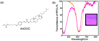
A similar method was used to prepare a magenta-coloured CLC film using a mixture of LC242, another type of chiral dopant and Irg907. The chiral dopant A4OOC (Fig. 7a) increases HTP via the trans-to-cis photoisomerisation of the cinnamate moiety.15 Although the cholesteric film of a 43.5/55/1.5 (w/w/w) mixture of LC242, A4OOC and Irg907 at 70 °C exhibited a reflection peak at λ0 = 605 nm, the transmittance spectrum of the film illuminated under UV light with an intensity of 50 mW cm−2 for 300 s showed two peaks at λ0 = 450 nm and 605 nm and the film exhibited a magenta colour, as shown in Fig. 7b. The chromaticity coordinates calculated from the transmittance spectrum were x = 0.32 and y = 0.22, indicating that the cholesteric colour was truly magenta. Thus, the atmospheric UV irradiation of CLCs of mixtures of a polymerisable LC monomer, PI and chiral dopant that changes the HTP via photoresponse provides an efficient method for preparing CLC films with broad and two distinct reflection bands that exhibit silver and the subtractive primary colour, respectively.
Conclusions
Planar-aligned CLC films with broad or two distinct reflection bands can be prepared by atmospheric UV irradiation of a mixture of a diacrylic nematic monomer, photoresponsive chiral dopant and PI. UV irradiation induces the photoreaction of the chiral dopant to change the HTP efficiently and photocleaves the initiator to generate radicals and initiate diacrylic monomer polymerisation. In such a way, UV-light illumination of the CLC film causes conflict between the pitch change and the freezing of the CLC structure. The polymerisation rate decreases with decreasing film depth because of atmospheric oxygen diffusing into the film and facilitating the change of the cholesteric pitch. The conflict becomes severe with increasing PI concentration and increasing UV-light power, resulting in a split of the reflection band into two distinct bands. Thus, this method can be used not only to broaden the reflection band to yield silver-coloured CLC films, but also to split the band to yield CLC films that assume a subtractive primary colour.Acknowledgements
This study was supported by the Strategic Promotion of Innovative Research and Development from the Japan Science and Technology Agency, JST.Notes and references
- W. Schlichting, S. Faris, B. Fan, J. Haag, Z. Lu, S. Kane, L. Li, T. Milster and H. Luo, Jpn. J. Appl. Phys., 1997, 36, 587–588 CrossRef CAS.
- V. I. Kopp, B. Fan, H. K. M. Vithana and A. Z. Genack, Opt. Lett., 1998, 23, 1707 CrossRef CAS.
- S. D. Jacobs, K. A. Cerqua, K. L. Marshall, A. Schmid, M. J. Guardalben and K. J. Skerrett, J. Opt. Soc. Am. B, 1988, 5, 1962 CrossRef CAS.
- N. Tamaoki, Adv. Mater., 2001, 13, 1135–1147 CrossRef CAS.
- J. Lub, P. van de Witte, C. Doornkamp, J. P. A. Vogels and R. T. Wegh, Adv. Mater., 2003, 15, 1420–1425 CrossRef CAS.
- J. Lub, W. P. M. Nijssen, R. T. Wegh, J. P. A. Vogels and A. Ferrer, Adv. Funct. Mater., 2005, 15, 1961–1972 CrossRef CAS.
- R. A. M. Hikmet and H. Kemperman, Nature, 1998, 392, 476–479 CrossRef CAS PubMed.
- D. J. Broer, J. Lub and G. N. Mol, Nature, 1995, 378, 467–469 CrossRef CAS.
- M. Mitov, Adv. Mater., 2012, 24, 6260–6276 CrossRef CAS PubMed.
- M. Mitov, A. Boudet and P. Sopéna, Eur. Phys. J. B, 1999, 8, 327–330 CrossRef CAS.
- S. H. Chen, J. C. Mastrangelo and R. J. Jin, Adv. Mater., 1999, 11, 1183–1186 CrossRef CAS.
- P. Van de Witte, M. Brehmer and J. Lub, J. Mater. Chem., 1999, 9, 2087–2094 RSC.
- J. Lub, D. J. Broer, R. T. Wegh, E. Peeters and B. M. I. van der Zande, Mol. Cryst. Liq. Cryst., 2005, 429, 77–99 CrossRef CAS.
- M. Tokita, M. Itoh, K. Marumo, Y. Harada, S. Kang, K. Sakajiri and J. Watanabe, Liq. Cryst., 2013, 40, 900–905 CrossRef CAS.
- F.-M. Hsieh, H. Fang and J.-H. Liu, Chem. Lett., 2010, 39, 485–487 CrossRef CAS.
| This journal is © The Royal Society of Chemistry 2015 |


