
 Open Access Article
 This Open Access Article is licensed under a
 Creative Commons Attribution 3.0 Unported Licence
Density functional theory study on the electronic properties and stability of silicene/silicane nanoribbons
Q. G.
Jiang
a,
J. F.
Zhang
*a,
Z. M.
Ao
*b and
Y. P.
Wu
a
aCollege of Mechanics and Materials, Hohai University, Nanjing 210098, China. E-mail: jfzhang@hhu.edu.cn
bCentre for Clean Energy Technology, School of Chemistry and Forensic Science, University of Technology Sydney, PO Box 123, Broadway, Sydney, NSW 2007, Australia. E-mail: zhimin.ao@uts.edu.au
First published on 3rd March 2015
Abstract
The thermal stability of silicene/silicane nanoribbons (SSNRs) has been investigated by using density functional theory calculations, where silicane is the fully hydrogenated silicene. It was found that the minimum energy barriers for the diffusion of hydrogen atoms at the zigzag and armchair interfaces of SSNRs are 1.54 and 1.47 eV, respectively, while the diffusion of H atoms at both interfaces is always endothermic. Meanwhile, the minimum diffusion energy barriers of one H atom and two H atoms on pristine silicene are 0.73 and 0.87 eV, respectively. Therefore, the thermal stability of SSNRs can be significantly enhanced by increasing the hydrogen diffusion barriers through silicene/silicane interface engineering. In addition, the zigzag SSNR remains metallic, whereas the armchair SSNR is semiconducting. However, the silicene nanoribbons part-determine the metallic or semiconducting behaviour in the SSNRs. This work provides fundamental insights for the applications of SSNRs in electronic devices.
1. Introduction
Two-dimensional silicene has recently been synthesized on Ag,1–3 Ir,4 Au,5 and ZrB26 substrates and attracted enormous interest in exploiting its potential applications for electronic devices because, similar to graphene, it has unique physical and electronic properties. However, several issues have restricted the development of silicene electronics, especially the absence of a band gap in the electronic structure of silicene.7–9 It has been reported that hydrogenation of silicene is an effective method to tune the band gap of silicene.10–12 However, the fully hydrogenated silicene–silicane, which can be synthesized by applying a strong perpendicular electric field in the presence of hydrogen gas12 or through applying strain in silicene,13 is a wide-gap insulator.10,14,15 The band gap of silicene can also be tuned by substrates.16,17 In addition, silicene nanoribbons (SNRs) offer the possibility to achieve tuneable band structures due to the size effect; namely the width of the nanoribbons and also the orientation of the edges. For example, SNRs can be changed from semiconducting to metallic by manipulating the structural parameters,9,18–21 similar to the case of graphene nanoribbons.22,23 Unfortunately, manipulating the edge structure and width of freestanding SNRs is very challenging in experiments.9,18,19Alternatively, high quality SNRs might be fabricated by selectively hydrogenating silicene, as proposed for the graphene system.24,25 A band gap opening in graphene with the patterned absorption of atomic hydrogen was recently found experimentally,26 which indicates that this may happen in the silicene system as well. Although experiments on hydrogenating silicene are absent, hybrid silicene/silicane nanoribbons (SSNRs) were studied by ab initio calculations.27 It was shown that the electronic and magnetic properties of SSNRs strongly depend on the degree of hydrogenation of the interface.27 However, the hydrogen diffusion associated with high mobility of the isolated H atoms on pristine silicene strongly affects the stability of the silicene/silicane interface, which needs to be clarified.
In this work, we study the stability of the silicene/silicane interface in hybrid nanoribbons by calculating the diffusion barrier of H atoms located at the silicene/silicane interface using density functional theory (DFT). All the possible diffusion pathways are analysed to find the minimum diffusion barrier, and therefore to provide a reference for designing viable silicene electronic devices that possess high thermal stability at standard operating conditions.
2. Calculation methods
The spin-unrestricted DFT calculations were carried out using the DMol3 package.28 The generalized gradient approximation (GGA) with the Perdew–Burke–Ernzerhof29 (PBE) exchange–correlation functional was used, which gives good agreement between the calculated and experimental crystallographic structure, and it is able to identify the most efficient catalysts through calculating reaction energy barriers, which are confirmed experimentally.30–32 DFT semicore pseudopotentials (DSPPs) core treatment is implemented for relativistic effects, which replaces core electrons by a single effective potential. Double numerical plus polarization (DNP) is employed as the basis set. The convergence tolerance of energy of 10−5 Hartree is taken (1 Hartree = 27.21 eV), and the maximal allowed force and displacement are 0.002 Hartree Å−1 and 0.005 Å, respectively. It was reported that the selection of exchange–correlation functional has an evidential effect on the adsorption energy results. However, the effect on the calculated reaction energy barriers is much smaller.33 To investigate the minimum energy pathway for the diffusion of H atoms at the silicene/silicane interface, linear synchronous transit/quadratic synchronous transit (LST/QST)34 and nudged elastic band (NEB)35 tools in the DMol3 module are used, which have been well-validated to determine the structure of the transition state and the minimum energy reaction pathway. The DFT+D method within the Grimme scheme36 is used in all calculations to consider the van der Waals forces. In the simulation, three-dimensional periodic boundary conditions are taken. The simulation cell for pristine silicene consists of a 3 × 3 silicene supercell with a vacuum width of 20 Å above the silicene layer to minimize the interlayer interaction. The k-point is set to 6 × 6 × 1, and all atoms are allowed to relax according to previous reports.123. Results and discussion
We first investigated the diffusion of a single H atom on pristine silicene with 3 × 3 supercell as shown in Fig. 1. The buckled silicene has a buckling of Δ = 0.45 Å, which is similar to the literature value of 0.44 Å.9 The H atom is chemically adsorbed on a Si atom at site 0 with an adsorption energy of −2.305 eV. There are three possible reaction pathways for the diffusion of the H atom, i.e., from site 0 to site 1 (path 1), from site 0 to site 2 (path 2) and from site 0 to site 3 (path 3). As shown in Fig. 1, the sites 1–3 denote the nearest Si, the second nearest Si, and opposite Si atoms, respectively. The Si atoms at sites 0 and 2 are on the upper layer of buckled silicene, while those at site 1 and site 3 are on the lower layer of buckled silicene. The detailed diffusion paths are calculated based on LST/QST and NEB calculations and the results are shown in Fig. 1. The results show that the hydrogen diffusion along path 1 and path 3 is endothermic with energy barriers Ebar of 0.73 eV and 1.21 eV, respectively [see Fig. 1(b) and (d)]. An energy barrier for hydrogen diffusion directly from site 0 to site 2 was not found. Therefore, another possible pathway is considered in Fig. 1(c), where the H atom diffuses from site 0 to site 1, then from site 1 to site 2. The energy barrier is 0.73 eV for path 2 as shown in Fig. 1(c). Because the H atom is more stable at site 2 than that at site 1 due to the lower total energy for the H atom at site 2, the H atom prefers to continue the diffusion from site 1 to site 2. By comparing the energy barrier with the critical barrier of Ecbar = 0.91 eV,37 the mobility at ambient temperature can be understood. The lower barriers for hydrogen diffusion along both path 1 and path 2 indicate higher mobility at room temperature.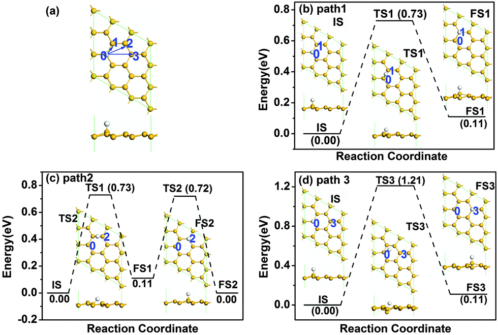 | ||
| Fig. 1 Atomic structure of pristine silicene with one H atom after relaxation (a), where the arrows indicate the different diffusion pathways of H atoms. The letters and numbers indicate different atomic positions. Panels (b)–(d) show the diffusion pathways 1–3 of a H atom on pristine silicene, respectively. IS, TS and FS represent initial structure, transition structure and final structure, respectively. Their atomic structures are given by the insets. The energy of the IS is taken to be zero. The units of Ebar and Er are eV, where Ebar is the energy barrier and Er is the reaction energy. The yellow and white atoms represent Si and H, respectively, in this and the following figures. | ||
The stability of two hydrogen atoms on pristine silicene was also considered, as shown in Fig. 2. After careful examination, we found that the most favourable configuration is that two H atoms adsorbed on the two Si atoms next to each other on opposite sides of the silicene, as shown in Fig. 2(a). There are four possible diffusion pathways for the H atom at the 0 site, i.e., from site 0 to site 1 (path 1), from site 0 to site 2 (path 2), from site 0 to site 3 (path 3) and from site 0 to site 4 (path 4). The diffusion barriers for the H atom at site 0 are 0.97, 1.06, 1.37 and 0.87 eV for pathways 1–4, respectively, where the minimum diffusion barrier is 0.87 eV along path 4. Therefore, with the presence of another H atom nearby, the diffusion barrier increases from 0.73 to 0.87 eV, but the barrier is still lower than the critical barrier of Ecbar = 0.91 eV,37 indicating the possible high mobility of H atoms on silicene at room temperature.
 | ||
| Fig. 2 Atomic structure of pristine silicene with two H atoms after relaxation (a), where the arrows indicate the different diffusion pathways of the H atom at the 0 position. The letters and numbers indicate different atomic positions. Panels (b)–(e) show the diffusion pathways 1–4 of the H atom at 0 position, respectively. | ||
Inspired by the stability enhancement of H atoms at the graphene/graphane interface,38 we considered the diffusion of H atoms at the silicene/silicane interface. The supercells used for the zigzag and armchair SSNRs are shown in Fig. 3(a) and (b), respectively. We minimized the interlayer interaction by allowing a vacuum width of 20 Å normal to the layer. For both types of nanoribbons, the Si atoms are displaced from the Si plane by about 0.25 Å due to the bonded H atoms. This value is similar to the shift of 0.30 Å that Si atoms experience when a H2 molecule undergoes dissociative adsorption on silicene.12 In both cases, this is a consequence of the change in the hybridization of the Si atoms from sp2 in silicene to sp3 in silicane. In addition, for the zigzag SSNR, both the silicene and the silicane nanoribbons are flat [see Fig. 3(a)]. However, the silicene and silicane layers are not in the same plane; they are connected with an angle of about 153° at the interface, which is similar to the previous reports for zigzag graphene/graphane nanoribbons.38 For the armchair SSNR [see Fig. 3(b)], the silicene and silicane regions are almost in the same plane with little curvature in the silicene nanoribbon.
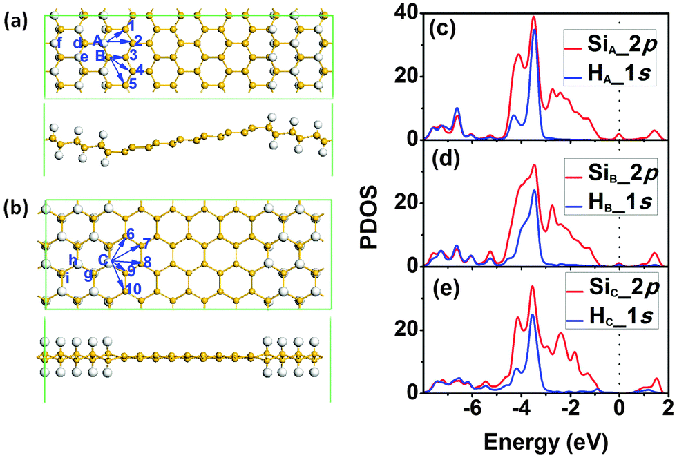 | ||
| Fig. 3 Atomic structure of SSNRs with (a) zigzag and (b) armchair interfaces after relaxation. The arrows indicate the different diffusion pathways of H atoms. The letters and numbers indicate different atomic positions. Panels (c)–(e) show the PDOS of Si and H atoms at A, B and C sites, respectively. | ||
We then analysed the stability of the two types of interfaces by calculating the diffusion barriers for hydrogen atoms at the interfaces. For the case of a zigzag interface, there are two types of Si and H atoms, denoted as sites A and B in Fig. 3(a). For the diffusion of the H atom at site A, there are two possible diffusion pathways labelled as 1 and 2 in Fig. 3(a). At site B, there are three possible diffusion pathways for the H atom that are labelled as 3, 4, and 5. In the case of an armchair interface, all the Si atoms at the interface are equivalent from a diffusion point of view. So there are five different diffusion pathways that we label as 6–10 in Fig. 3(b). When analysing the diffusion paths, we find that all of the diffusion is along linear pathways and also that the H atom is free without directly binding to any Si atom in the transition state (TS). The PDOSs of Si and H at sites A, B and C are also plotted in Fig. 3(c)–(e), which shows that the strength of the Si–H bond is the largest at site A, while that of the Si–H bond at sites B and C is similar but weaker from the weight of the overlap of the Si and H bands. It indicates that H atoms at sites B and C are more active.
The diffusion barriers of both types of silicene/silicane interfaces with different paths are summarized in Table 1. For the zigzag interface, the diffusion barriers at site A are 1.75 and 2.05 eV for pathways 1 and 2, respectively, where the former is the minimum diffusion barrier. The diffusion barriers at site B are 1.54, 1.56 and 2.25 eV for pathways 3–5, respectively, where the minimum diffusion barrier at site B is 1.54 eV along path 3. As a result, site A is more stable than site B. After LST/QST and NEB calculations, the detailed reaction pathway and the energy barrier for hydrogen diffusion along path 3 is shown in Fig. 4(a) where the initial state (IS), the final state (FS), and the atomic structure of the transition state (TS) are given. For the armchair interface, the energy barriers at site C are 1.47, 1.69, 2.15, 1.61 and 2.11 eV for diffusion pathways 6–10, respectively. Thus, the H diffusion path on armchair interfaces with the minimum energy barrier of 1.47 eV from site C to the second nearest Si atom is path 6. The corresponding reaction pathway and energy barrier are present in Fig. 4(b). Since the occurrence of the surface reaction needs Ebar > Ecbar = 0.91 eV at ambient temperature,37 both the zigzag and armchair interfaces are stable at room temperature.
| Diffusion pathway | E bar (eV) | E r (eV) | E bar′ (eV) | ||
|---|---|---|---|---|---|
| Zigzag interface | A | 1 | 1.75 | 1.00 | 0.75 |
| 2 | 2.05 | 1.68 | 0.37 | ||
| 3 | 1.54 | 0.88 | 0.66 | ||
| B | 4 | 1.56 | 0.92 | 0.64 | |
| 5 | 2.25 | 0.59 | 1.66 | ||
| Armchair interface | C | 6 | 1.47 | 0.70 | 0.77 |
| 7 | 1.69 | 1.19 | 0.50 | ||
| 8 | 2.15 | 0.79 | 1.36 | ||
| 9 | 1.61 | 1.26 | 0.35 | ||
| 10 | 2.11 | 0.43 | 1.68 | ||
 | ||
| Fig. 4 The diffusion pathway 3 of H atom on SSNR with zigzag interface (a), and the diffusion pathway 6 of H atom on SSNR with armchair interface (b). The H atoms at sites B and C are represented by green balls. | ||
In light of the above analysis, we can see that the minimum diffusion barriers for both the armchair and zigzag interfaces are almost 2 times larger than the energy barrier for H diffusion on pristine silicene. From the diffusion energy in Table 1, the total energy increases ∼1 eV after diffusion for all the cases. At the same time, the reverse diffusion energy barrier Ebar′ in Table 1 is much lower than the corresponding diffusion barrier Ebar. Therefore, the exothermic reverse diffusion is energy preferred with a lower diffusing energy barrier, which confirms the enhanced stability of H atoms at silicene/silicane interfaces from another side. Note that the backward barriers (Ebar′) for H diffusion are defined as the energy difference between the final state and the TS state, and can be obtained from Table 1 as the difference between the diffusion barrier Ebar and the reaction energy Er.
Such stability enhancement can be understood by calculating the binding energy of the H atoms under different conditions, which are proportional to the strength of the Si–H bonds. The binding energies (Eb) were calculated by Eb = Ei − (Ef + EH), where Ei is the initial energy of the system, Ef is the energy of the system after removing the H atom, and EH is the energy of an isolated H atom. For the zigzag interface, we found that the binding energy of the Si–H bond at sites A and B are −3.80 and −3.34 eV, respectively. While for a H atom at site C of the armchair interface, this value is −3.23 eV. All of these values are larger than the binding energy of an isolated H atom on a silicene supercell containing 18 Si atoms (−2.31 eV). This indicates the stability enhancement of H atoms at silicene/silicane interfaces. The results of the binding energies also explain why it is easier to move the H atoms from site B (Eb = −3.34 eV) than from site A (Eb = −3.80 eV) in the zigzag interface, and why moving the H atoms from site C (Eb = −3.23 eV) in the armchair interface is slightly easier than that from site B (Eb = −3.34 eV) in the zigzag interface. As a result, the zigzag interface is slightly more stable than the armchair interface.
To further understand the higher stability of the H atom at site A, we analyse the Mulliken atomic charges of Si and H atoms at different sites. Table 2 gives the atomic charges of atoms near the interfaces. We can see that at both interfaces (i.e., at sites A, B, and C) Si atoms are less positive and the corresponding H atoms are less negative than those in silicane away from the interfaces. Furthermore, it also shows that both interfaces mainly affect the charge distribution of the first row of atoms at the interfaces. This result agrees with the fact that an interface influences mainly the atoms of the first two rows.38,39 It is known that the atomic charge is mostly affected by the atoms belonging to the same silicon ring, especially the nearest atoms. For the silicon and hydrogen atoms at site A, they have similar nearest atoms as sites in the silicane region far apart from the interface, where the three nearest Si atoms are bonded by sp3 orbitals. For the Si and H atoms at site B, only two nearest Si atoms are bonded by sp3 orbitals; the third on its right hand side at site 3 is bonded by sp2 orbitals. Therefore, the effect of the interface on site B is stronger than that on site A. On the other hand, for both sites A and B, there are three Si atoms bonded by sp2 orbitals in the silicon ring. Thus, the charge distribution of the atoms on both sites is changed by the interface. A similar reasoning can be applied to the charge difference on the atoms at site C of the armchair interface. Therefore, the H atom at site B (−0.053e) and that at site C (−0.050e) are more chemically active than that at site A (−0.062e) due to the weak Si–H bond strength. In addition, one H atom at site 0 (−0.035e) on pristine silicene is less charged than that at the interface of SSNRs, indicating the lower diffusion barrier for the hydrogen atom on pristine silicene.
| Atom site | Si atom | H atom | |
|---|---|---|---|
| Zigzag interface | A | 0.066 | −0.062 |
| B | 0.064 | −0.053 | |
| d | 0.071 | −0.065 | |
| e | 0.067 | −0.067 | |
| f | 0.068 | −0.067 | |
| 1 | −0.006 | ||
| 2 | −0.007 | ||
| 3 | −0.006 | ||
| 4 | −0.007 | ||
| 5 | −0.006 | ||
| Armchair interface | C | 0.064 | −0.050 |
| g | 0.065 | −0.064 | |
| h | 0.067 | −0.066 | |
| i | 0.068 | −0.067 | |
| 6 | −0.011 | ||
| 7 | 0.001 | ||
| 8 | 0.001 | ||
| 9 | −0.001 | ||
| 10 | −0.001 | ||
| One H on pristine silicene | 0 | 0.064 | −0.035 |
| Two H on pristine silicene | 0 | 0.062 | −0.046 |
To understand the electronic properties of SSNRs, the band structures of zigzag and armchair SSNRs are calculated and the results are shown in Fig. 5. For the zigzag SSNR in Fig. 5(b), the Fermi level crosses over the conduction band due to the electron inefficiency, indicating n-type doping. From the charge distribution of the LUMO state, we can see that the conduction band across the Fermi level is mainly contributed to by the silicene nanoribbon. The PDOS of the Si atom [site d in Fig. 3(a)] in the silicane part, and Si atom [site 2 in Fig. 3(a)] in the silicene part are shown in Fig. 5(a). Clearly, the conduction band around the Fermi level is mostly contributed to by the Si-2p states in the silicene part, consistent with the charge distribution of the LUMO state. The silicene nanoribbon has high mobility due to its delocalized nature, which implies that the zigzag SSNR should be highly conductive.
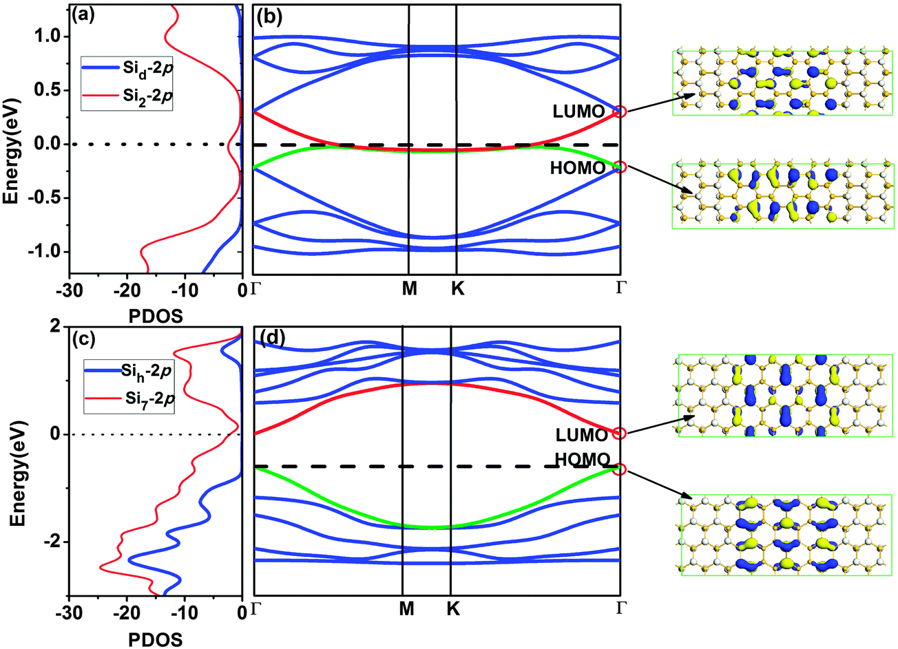 | ||
| Fig. 5 The PDOS (a) and band structure (b) of the SSNRs with zigzag interface. The PDOS (c) and band structure (d) of the SSNRs with armchair interface. The numbers after the element symbol denote the atomic positions in the SSNRs. The vertical lines indicate the Fermi level. The charge distributions of LUMO and HOMO states at the Γ point are also given in the right panel. The blue and yellow colours indicate different signs of the orbital wave function. | ||
For armchair SSNRs [see Fig. 5(d)], the Fermi level moves down to the exact top of the valence band and the armchair SSNR changes to become a pristine semiconductor with a band gap of 0.30 eV. The charge distribution of the HOMO and LUMO states indicate that the band gap is mainly determined by the silicene nanoribbon. The PDOS of the Si atom [site h in Fig. 3(b)] in the silicane part, and the Si atom [site 7 in Fig. 3(b)] in the silicene part is shown in Fig. 5(c), where the conduction band minimum (CBM) and valence band maximum (VBM) are mostly contributed to by Si-2p states in the silicene part. This is consistent with the charge distribution of the HOMO and LUMO states. Therefore, the zigzag SSNRs maintain a metallic character while the armchair SSNRs turn out to be semiconducting.
4. Conclusion
In summary, we have studied the stability of SSNRs with both zigzag and armchair interfaces by calculating the diffusion barriers of H atoms using the DFT method. We found a significantly enhanced stability of H atoms at the silicene/silicane interfaces, compared with the case of an isolated hydrogen atom and a pair of hydrogen atoms on pristine silicene. This enhancement is induced by the increase of the Si–H bond strength at the silicene/silicane interfaces. In addition, the band gap of armchair SSNRs is open while the zigzag SSNRs remain metallic. Our results show that both types of silicene/silicane interfaces in hybrid nanoribbons are rather stable, which increases the feasibility for future technological applications of these systems.Acknowledgements
This work was supported by the Fundamental Research Funds for the Central Universities (Grant No. 2014B13414 and 2013B34414). ZA acknowledges the financial supports from the Chancellor's Research Fellowship Program of the University of Technology, Sydney. This research is supported by the National Computational Infrastructure (NCI) through the merit allocation scheme and used NCI resources and facilities in Canberra, Australia.References
- B. Lalmi, H. Oughaddou, H. Enriquez, A. Kara, S. Vizzini, B. Ealet and B. Aufray, Appl. Phys. Lett., 2010, 97, 223109 CrossRef PubMed.
- B. J. Feng, Z. J. Ding, S. Meng, Y. G. Yao, X. Y. He, P. Cheng, L. Chen and K. H. Wu, Nano Lett., 2012, 12, 3507–3511 CrossRef CAS PubMed.
- A. Fleurence, R. Friedlein, T. Ozaki, H. Kawai, Y. Wang and Y. Yamada-Takamura, Phys. Rev. Lett., 2012, 108, 245501 CrossRef.
- L. Meng, Y. Wang, L. Zhang, S. Du, R. Wu, L. Li, Y. Zhang, G. Li, H. Zhou, W. A. Hofer and H. J. Gao, Nano Lett., 2013, 13, 685–690 CrossRef CAS PubMed.
- M. R. Tchalala, H. Enriquez, A. J. Mayne, A. Kara, S. Roth, M. G. Silly, A. Bendounan, F. Sirotti, T. Greber, B. Aufray, G. Dujardin, M. Ait Ali and H. Oughaddou, Appl. Phys. Lett., 2013, 102, 083107 CrossRef PubMed.
- A. Fleurence, R. Friedlein, T. Ozaki, H. Kawai, Y. Wang and Y. Yamada-Takamura, Phys. Rev. Lett., 2012, 108, 245501 CrossRef.
- K. Takeda and K. Shiraishi, Phys. Rev. B: Condens. Matter Mater. Phys., 1994, 50, 14916 CrossRef CAS.
- G. Guzman-Verri and L. Lew Yan Voon, Phys. Rev. B: Condens. Matter Mater. Phys., 2007, 76, 075131 CrossRef.
- S. Cahangirov, M. Topsakal, E. Aktürk, H. Sahin and S. Ciraci, Phys. Rev. Lett., 2009, 102, 236804 CrossRef CAS.
- T. H. Osborn, A. A. Farajian, O. V. Pupysheva, R. S. Aga and L. C. Lew Yan Voon, Chem. Phys. Lett., 2011, 511, 101–105 CrossRef CAS PubMed.
- P. Zhang, X. D. Li, C. H. Hu, S. Q. Wu and Z. Z. Zhu, Phys. Lett. A, 2012, 376, 1230–1233 CrossRef CAS PubMed.
- W. C. Wu, Z. M. Ao, T. Wang, C. M. Li and S. Li, Phys. Chem. Chem. Phys., 2014, 16, 16588–16594 RSC.
- W. C. Wu, Z. M. Ao, C. H. Yang, S. Li, G. X. Wang, C. M. Li and S. Li, J. Mater. Chem. C, 2015, 3, 2593–2602 RSC.
- L. C. L. Y. Voon, E. Sandberg, R. S. Aga and A. A. Farajian, Appl. Phys. Lett., 2010, 97, 163114 CrossRef PubMed.
- N. Gao, W. T. Zheng and Q. Jiang, Phys. Chem. Chem. Phys., 2012, 14, 257–261 RSC.
- N. Gao, J. C. Li and Q. Jiang, Phys. Chem. Chem. Phys., 2014, 16, 11673–11678 RSC.
- N. Gao, J. C. Li and Q. Jiang, Chem. Phys. Lett., 2014, 592, 222–226 CrossRef CAS PubMed.
- C. Y. Xu, G. F. Luo, Q. H. Liu, J. X. Zheng, Z. M. Zhang, S. Nagase, Z. X. Gao and J. Lu, Nanoscale, 2012, 4, 3111–3117 RSC.
- Y. Ding and Y. L. Wang, Appl. Phys. Lett., 2013, 102, 143115 CrossRef PubMed.
- Q. Wu, X. H. Wang, T. A. Niehaus and R. Q. Zhang, J. Phys. Chem. C, 2014, 118, 20070–20076 CAS.
- F. B. Zheng, C. W. Zhang, S. S. Yan and F. Li, J. Mater. Chem. C, 2013, 1, 2735–2743 RSC.
- Q. Q. Dai, Y. F. Zhu and Q. Jiang, J. Phys. Chem. C, 2013, 117, 4791–4799 CAS.
- Q. Q. Dai, Y. F. Zhu and Q. Jiang, Phys. Chem. Chem. Phys., 2014, 16, 10607–10613 RSC.
- A. K. Singh and B. I. Yakobson, Nano Lett., 2009, 9, 1540–1543 CrossRef CAS PubMed.
- P. Sessi, J. R. Guest, M. Bode and N. P. Guisinger, Nano Lett., 2009, 9, 4343–4347 CrossRef CAS PubMed.
- P. Koskinen, S. Malola and H. Häkkinen, Phys. Rev. B: Condens. Matter Mater. Phys., 2009, 80, 073401 CrossRef.
- G. H. Li, J. Tan, X. D. Liu, X. P. Wang, F. Li and M. W. Zhao, Chem. Phys. Lett., 2014, 595, 20–24 CrossRef PubMed.
- B. Delley, J. Chem. Phys., 2000, 113, 7756–7764 CrossRef CAS PubMed.
- J. P. Perdew, K. Burke and M. Ernzerhof, Phys. Rev. Lett., 1996, 77, 3865 CrossRef CAS.
- P. Zhang, X. F. Chen, J. S. Lian and Q. Jiang, J. Phys. Chem. C, 2012, 116, 17572–17579 CAS.
- J. D. Baran, H. Grönbeck and A. Hellman, J. Am. Chem. Soc., 2014, 136, 1320–1326 CrossRef CAS PubMed.
- G. X. Chen, Y. Zhao, G. Fu, P. N. Duchesne, L. Gu, Y. P. Zheng, X. F. Weng, M. S. Chen, P. Zhang, C. W. Pao, J. F. Lee and N. F. Zheng, Science, 2014, 344, 495–499 CrossRef CAS PubMed.
- A. Roldán, J. M. Ricart and F. Illas, Theor. Chem. Acc., 2009, 123, 119–126 CrossRef.
- T. A. Halgren and W. N. Lipscomb, Chem. Phys. Lett., 1977, 49, 225–232 CrossRef CAS.
- G. Henkelman and H. Jonsson, J. Chem. Phys., 2000, 113, 9978–9985 CrossRef CAS PubMed.
- S. Grimme, J. Comput. Chem., 2006, 27, 1787–1789 CrossRef CAS PubMed.
- D. C. Young, Computational Chemistry: A Practical Guide for Applying Techniques to Real World Problems, Wiley, New York, 2001 Search PubMed.
- Z. M. Ao, A. D. Hernández-Nieves, F. M. Peeters and S. Li, Appl. Phys. Lett., 2010, 97, 233109 CrossRef PubMed.
- C. Q. Sun, Prog. Solid State Chem., 2007, 35, 1–159 CrossRef CAS PubMed.
| This journal is © The Royal Society of Chemistry 2015 |