
 Open Access Article
 This Open Access Article is licensed under a
 Creative Commons Attribution 3.0 Unported Licence
Highly efficient, coking-resistant SOFCs for energy conversion using biogas fuels†‡
Jianjun
Ma§
,
Cairong
Jiang§
,
Paul A.
Connor
,
Mark
Cassidy
and
John T. S.
Irvine
*
School of Chemistry, University of St Andrews, The Purdie Building, St Andrews, Fife, Scotland, UK KY16 9ST. E-mail: jtsi@st-andrews.ac.uk; Fax: +44 (0) 133 4463808; Tel: +44 (0) 133 4463817
First published on 18th August 2015
Abstract
Solid oxide fuel cells (SOFCs) afford an opportunity for the direct electrochemical conversion of biogas with high efficiency; however, direct utilisation of biogas in nickel-based SOFCs is a challenge as it is subject to carbon deposition. A biogas composition representative of a real operating system of 36% CH4, 36% CO2, 20% H2O, 4% H2 and 4% CO used here was derived from an anode recirculation method. A BaZr0.1Ce0.7Y0.1Yb0.1O3−δ (BCZYYb) infiltrated Ni-YSZ anode was investigated for biogas conversion. The infiltration of BCZYYb significantly promoted the electrochemical reactions and the cells exhibited high power output at the operational temperatures of 850, 800 and 750 °C. At 800 °C, supplied with a 20 ml min−1 biogas, the cell with a BCZYYb-Ni-YSZ anode, generated 1.69 A cm−2 at 0.8 V with an optimal amount of 0.6 wt% BCZYYb, whereas only 0.65 A cm−2 was produced with a non-infiltrated Ni-YSZ in the same conditions. At 750 °C, a maximum power density of 1.43 W cm−2 was achieved on a cell with a BCZYYb-Ni-YSZ anode, a 3 μm dense YSZ film electrolyte, a Gd0.1Ce0.9O2 (GDC) buffer layer and a La0.6Sr0.4Co0.2Fe0.8O3–Gd0.1Ce0.9O2 (LSCF-GDC) composite cathode. The cell remained stable, while operating at 0.8 V for 50 hours with a current density of 1.25 A cm−2. A well-designed cell structure and selected components made it possible to obtain excellent performance at good fuel utilisation. The analysis of gases in open-circuit conditions or under various current loads suggested that the prevalent reaction was reforming of methane without coking. This study demonstrates that the BCZYYb-Ni-YSZ is a promising electrode for carbon-containing fuel.
1. Introduction
Biogas, a renewable clean and easily controlled energy source, like solar and wind energy, is produced by the breakdown of organic matter in the absence of oxygen. It is an alternative to fossil fuels (petroleum, coal), not only to reduce an overall increase in greenhouse gases emissions, but to utilise a certain number of waste products, such as manure, sewage, municipal waste, plant material and crops residues.1 An underexploited potential energy source, biogas is composed of mainly methane (50–75%) and carbon dioxide (25–50%) with other minor gases.2 Because of the high level of carbon dioxide, it can only be utilised at low conversion efficiency levels in the conventional power generation system. Now it is being considered for use in alternative systems to generate electricity more efficiently.3–5Solid oxide fuel cells (SOFCs) are a new technology for converting the chemical energy of hydrocarbon or biogas into electricity with high efficiency and fuel flexibility.6 SOFCs can operate within a wide temperature range from low temperatures (400–600 °C) to high temperatures (over 1000 °C) by selecting suitable electrolyte and electrode materials. Although operation of solid oxide fuel cells at low temperature is desirable in terms of cell life and cost, intermediate or even high temperature operation can be beneficial to the internal reforming reactions of methane or other hydrocarbon fuels.5,7–10 In addition, the direct heat exchange between the endothermic internal reforming reactions and the exothermic electrochemical reactions in the fuel cells increases the total system efficiency.11,12
In general, steam reforming and dry reforming reactions are considered as the main reactions in a biogas-fuelled cell.
| CH4 + H2O → CO + 3H2 | (1) |
| CH4 + CO2 → 2CO + 2H2 | (2) |
There are, however, other reaction paths, such as the water-gas shift reaction.
| CO + H2O ↔ CO2 + H2 | (3) |
Depending on the reaction conditions, the equilibrium for the water-gas shift can be pushed in either direction. In fuel cell systems, the dominant reactions will be dependent on the gas concentration, temperatures and system design. The task for researchers is to find good electrode materials that can operate in biogas fuel and generate good power output with good durability.
Nickel is a commonly used catalyst13 due to its excellent catalytic activity for direct oxidation or reforming reactions of hydrocarbon fuel. Therefore it is still considered to be a good catalyst for biogas conversion despite of extensive research on perovskite, La0.75Sr0.25Cr0.5Mn0.5O3 (ref. 14) and Sr2Mg1−xMnxMoO6−δ,15 Cu-based electrode (Cu-YSZ, Cu-Ceria),13,16 precious metal (Rh, Ru, Ir, Pd, Pt)17–20 or precious metal impregnated supports.16,21,22 However, when a nickel electrode is used in a biogas of 60% CH4 and 40% CO2, carbon coking occurs resulting in degradation of the cell performance, or even deactivation of the nickel electrode due to a build-up of carbon on the nickel surface.23–25 In order to avoid carbon deposition an additional reforming agent is therefore required. This could be air, steam or anode recycling containing CO2 and steam. It was reported that a high ratio of steam/methane (i.e., 2)26 or carbon dioxide/methane (i.e., 1.5)10,27 was needed for steam reforming and dry reforming, respectively. This dilutes the fuel concentration and subsequently reduces the fuel utilisation and electrical efficiency. Since SOFCs with anode gas recirculation have higher electrical and thermal efficiencies than non-recycling SOFCs,28,29 it is an effective strategy to combine dry reforming and steam reforming, because carbon dioxide and steam are available from partial anode exhaust gas recycling.30 In comparison with external steam generation, anode exhaust gas recycling provides an internal steam circuit, which eliminates the need for a waste heat recovery steam generator such as the boiler, thus reducing the capital cost of the system. At the same time, the steam content of the exhaust gas is reduced and this elevates efficiency of the total system, by increasing the sensible thermal energy of the exhaust gas.
Viana showed that good reverse water-gas shift activity was often associated with proton conducting oxide perovskites giving an early indication that these might be beneficial in anodes for hydrocarbon fuelled SOFC.31 Proton conductors, BaZr0.9Yb0.1O3−δ,32 BaZr0.1Ce0.7Y0.2O3−δ33 and Ni–BaZr0.1Ce0.7Y0.1Yb0.1O3−δ34 were also reported to have excellent resistance to sulphur poisoning. Cells with those proton conductors have been running in hydrocarbon fuels without coking and have been operating in high sulphur hydrogen without failure. A NiO-4% Zn, doped with BaZr0.8Y0.2O3 was used the anode for the CH4/CO2 = 1![[thin space (1/6-em)]](https://www.rsc.org/images/entities/char_2009.gif) :1 biogas with 3% H2O and the cell displayed good durability even though carbon formation was thermodynamically favoured using this CH4/CO2 stoichiometric ratio, shown in the C–H–O equilibrium diagram.35 The application of BaZr0.1Ce0.7Y0.1Yb0.1O3−δ in biogas fuels has not yet been reported.
:1 biogas with 3% H2O and the cell displayed good durability even though carbon formation was thermodynamically favoured using this CH4/CO2 stoichiometric ratio, shown in the C–H–O equilibrium diagram.35 The application of BaZr0.1Ce0.7Y0.1Yb0.1O3−δ in biogas fuels has not yet been reported.
Apart from the carbon deposition, another important parameter to be evaluated in the use of biogas in SOFC, is the power output. Some researchers have performed some experiments to enhance the anode performance. The cell of Ni-BZYZn/BZYZn/Pt developed by Luisetto et al.35 generated a maximum power density of 20 mW cm−2 at 750 °C, which was limited by a large ohmic resistance, and/or possibly by the poor catalytic activity of the electrode. Wang et al. reported a Ni-based cell generated 424 mW cm−2 at 800 °C in a simulated biogas of 52.2% CH4, 46.3% CO2 and 1.5% N2, but carbon deposition caused quick degradation of cell performance.36 This was improved by introduction of Al2O3, however, some carbon was still observed by SEM-EDX test after operation at 750 °C for over 120 hours.
At the operational temperatures of the solid oxide fuel cells, the cathode polarisation resistance is a major loss as well.37–39 This can be improved by choosing materials with high catalytic activity or by tailoring the microstructure.40,41 (La, Sr)(Co, Fe)O3 (LSCF), a mixed ion-electron conductor, was reported to have good electronic and ion conductivity and was suitable for intermediate temperature ranges (700 to 900 °C).42 Especially if low temperatures are desirable for the application.
In this study, we aim to develop biogas fuelled cells that they are coking free and have good durability combined with good fuel utilisation. Here a simple route will be developed to prepare a modified Ni-YSZ anode with BaZr0.1Ce0.7Y0.1Yb0.1O3−δ (BCZYYb) infiltration. Gas components will be detected in open circuit conditions and under current load to explore possible reaction mechanism.
2. Experimental and theoretical calculation
2.1. Biogas composition
Thermochemical calculations were carried out using the program, HSC chemistry (version 5.0, Outokumpu Research Oy, Finland). The details of these calculations can be found in the previous literature.43 The calculations were performed by assuming a reactor was supplied with a mixture of fuel gas normalized to 1 kmol, and the amount of gas, liquid, or solid products in thermodynamic equilibrium were numerically derived. This was performed over a temperature range of 100 to 900 °C in steps of 10 °C. As solid carbon, only graphite was taken into account, although various carbon-based materials such as amorphous carbon, carbon nanotubes, and carbon nanofibers have slightly different thermochemical properties. As the equilibrium products can be in a gas state and/or a solid state (graphite) at elevated temperatures, most of the following results calculated in this study were shown as the amounts of products rather than concentrations. For the sake of simplicity, only the following species were considered: H2 (g), H2O (g), O2 (g), CO (g), CO2 (g), CH4 (g), and solid graphite. Chemical compositions were numerically derived by assuming complete thermodynamic equilibrium. The total pressure was 1 bar. Partial pressures were derived from the chemical compositions by assuming that fuel gases can be regarded as ideal gases.A biogas of 63% CH4 and 37% CO2, which has a typical amount of methane for different feedstocks, was selected as an original biogas.2 This biogas is prone to form carbon at the operational temperatures (e.g. 750–850 °C) of fuel cells (no. 1 biogas, in Fig. 1). We anticipate that a practical small system will utilise anode recirculation to minimise carbon formation and best utilise thermal energy and this would mean a modified biogas composition needs to be considered in solid oxide fuel cells. Starting from the original biogas composition (no. 1) methane will be converted into CO, H2 according to reforming reactions and then oxidised. A typical overall fuel conversion rate of 80% was chosen and 25% of the anode exhaust could be recycled. An iterative method was used to calculate a steady-state composition. It was assumed that the gases were at thermodynamic equilibrium and the gas composition was calculated with HSC chemistry software. A single-pass fuel utilisation was 73.3%. 25% of the anode exhaust gas was added into the original gas. Then the cycle described above was repeated until a steady-state composition of gases was obtained. The overall fuel utilisation was 80%. This slightly higher overall fuel utilisation than a singly-pass fuel utilisation of 73.3% matched the report by Powell et al.44 Fuel utilisation will be discussed in Section 3.3. The final steady-state biogas is defined as a recirculated biogas and its composition was 36% CH4, 36% CO2, 20% H2O, 4% H2 and 4% CO. The details of the calculation were shown elsewhere.45 This recirculated biogas (no. 2, Fig. 1) is in the safe region and should not result in carbon deposition above 720 °C. In the following, we will be using the recirculated biogas of 36% CH4, 36% CO2, 20% H2O, 4% H2 and 4% CO to do further research.
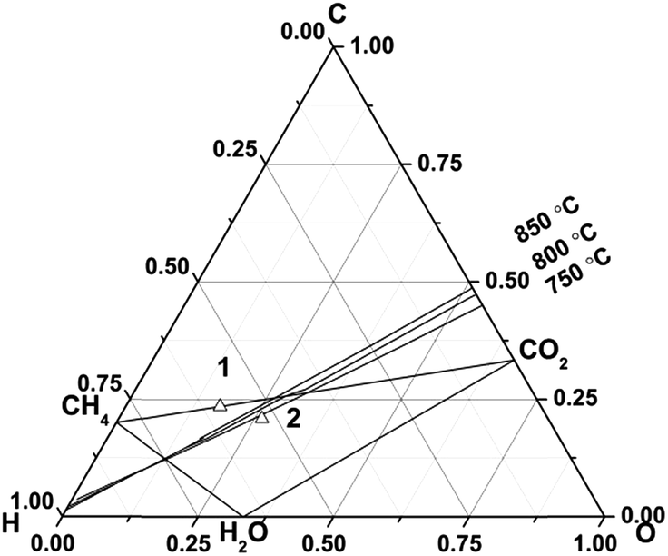 | ||
| Fig. 1 An equilibrium diagram of the region for carbon deposition at 750–850 °C for an original biogas of 63% CH4 and 37% CO2 (no. 1) and a recirculated biogas of 36% CH4, 36% CO2, 20% H2O, 4% H2, 4% CO (no. 2). | ||
2.2. Experimental
:50 and 70:30, respectively. The thickness of the LSM-YSZ and the LSCF-GDC layers were around 20 μm. The cathode area, calculated as the cell active area, was 1 cm2. Platinum paste (Gwent Group, 70%) and gold paste (conductor paste M-9875, METALOR Technologies UK Ltd) were used as the cathode and anode current collectors, respectively, sintering at 900 °C for 30 minutes.
:EDTA:metal-ion 1.5:1:1. A final solution was obtained by adjusting the pH value to ∼7 with NH3·6H2O (Fisher chemical), and this was then infiltrated into the NiO-YSZ anode substrate and calcined at 1100 °C for 2 hours. The infiltration amount used was 0.3 wt%, 0.6 wt%, 1.0 wt% and 1.6 wt% of the cell weight, accordingly the number of infiltration times were 2, 3, 6 and 9. The cells with BaZr0.1Ce0.7Y0.1Yb0.1O3−δ (BCZYYb) were defined as BCZYYb-0 wt%, BCZYYb-0.6 wt%, BCZYYb-1.0 wt% and BCZYYb-1.6 wt%. The consequence of the cell preparation procedure was the half cell of the NiO-YSZ/YSZ was made first. And then when the LSM was used for the cathode, the LSM-YSZ and the infiltrated BCZYYb were sintered at 1100 °C for 2 hours. When the LSCF was used the cathode, the GDC interlayer was sintered 1150 °C, and then the infiltrated BCZYYb was sintered at 1100 °C for 2 hours and at last the LSCF-GDC electrode was sintered at 1000 °C for 2 hours.
000 Hz to 0.1 Hz in open-circuit conditions.
After the nickel oxide had been completely reduced to nickel, the anode gas was connected to a bubbler to humidify the hydrogen. It was then switched to a steam generator to gradually increase the steam content, until 20% H2O was obtained. The water content during testing was monitored by a dewpoint sensor (Vaisala). A biogas with desired compositions was switched on. The gases were mixed to the correct ratio using mass flow controllers (Bronkhorst), with a total flow rate of a 300 ml min−1, consisting of 285 ml min−1 of the biogas composition, balanced with argon. The cells were characterised in dry hydrogen, wet hydrogen, steam hydrogen and the recirculated biogas mentioned above. In the biogas, the cell was kept in open-circuit conditions for 2 hours to record the anode exhaust gas. The electrochemical polarisation curves and the EIS of the cells were tested from 850 °C to 750 °C, at a 50 °C interval, using various flow rates. To simplify the experiments, the optimisation of infiltration BCZYYb was carried out on the cell with a LSM-YSZ cathode rather than a LSCF-GDC cathode, to avoid the extra work of the screen-printing of the GDC interlayer.
There should be no change in the carbon content in the original gas and in the anode exhaust gas as long as there is no carbon deposition.
| Carbon content (CH4 + CO + CO2)input = Carbon content (CH4 + CO + CO2)output |
The flow rate of argon in input is equal to the flow rate of argon from output.
| f(Ar(input)) = f(Ar(output)) |
The content of CH4, CO and CO2 was recalculated by subtracting hydrogen and argon from the GC results.
The flow rate of hydrogen from output was calculated using the following equation:
| f(H2 out) = 2 × (f(CH4 in) − f(CH4 out)) − f(H2 in) |
Conversion rate of CH4 was calculated in (f(CH4 in) − f(CH4 out))/f(CH4 in) × 100%.
3. Results and discussion
3.1. Cell structure
A SOFC with a thin electrolyte film is desirable to achieve sufficient energy conversion rates and obtain a reasonable power output.47 Here a NiO-YSZ anode-supported fuel cell was developed with a thin YSZ electrolyte fabricated by slurry coating.46 The microstructure of an example anode supported fuel cell (Ni-YSZ (BCZYYb-0.6 wt%)/YSZ/GDC/LSCF-GDC) is shown in Fig. 2a. The thickness of the YSZ electrolyte membrane is about 3 μm with neither crack nor pinhole, giving a very low ohmic resistance from the electrolyte due to the thin electrolyte.48 The interlayer of GDC is about 3 μm. Therefore, the cell performance of the anode-supported cell is dominated by the electrode polarisation losses49 from both the anode and the cathode. Fig. 2a shows that the Ni-YSZ anode has appropriate porosity for gas to pass through to the three-phase boundary, thus allowing participation in the reactions. The microstructures of Ni-YSZ anodes infiltrated with and without BCZYYb are shown in Fig. 2b. The framework of the anodes is covered with BCZYYb particles to form a layer. Clear boundaries of BCZYYb layers are observed around the edges of the pores. These layers of BCZYYb protect the Ni-YSZ from direct contact with the biogas.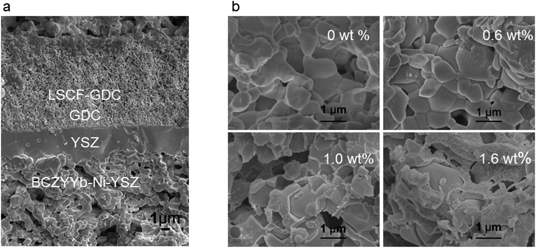 | ||
| Fig. 2 Microstructure of the cells. (a) An example of cross-sectional SEM microstructure of a tested cell with a Ni-YSZ anode infiltrated with BCZYYb-0.6 wt%, a YSZ electrolyte, a Gd0.1Ce0.9O2 (GDC) layer and a La0.6Sr0.4Co0.2Fe0.8O3 (LSCF)-GDC cathode after being tested at 850 °C, 800 °C and 750 °C; this cell ran at 0.8 V (1.25 A cm−2) at 750 °C for 50 hours; (b) anode microstructure of the Ni-YSZ cells infiltrated with BCZYYb after electrochemical tests. | ||
3.2. Electrochemical performance
Fig. 3a compares the current densities obtained from differing cells with a infiltrated BCZYYb or a non-infiltrated BCZYYb-Ni-YSZ anode at 0.8 V, as obtained from the current density–voltage curves (Fig. S2†). The optimisation experiments were performed on the cell configuration of BCZYYb-Ni-YSZ/YSZ/LSM-YSZ. All the infiltrated BCZYYb Ni-YSZ cells have a better cell performance than the non-infiltrated one. The infiltration of BCZYYb effectively enhanced the cell performance in all kinds of fuels, dry hydrogen, wet hydrogen, steam hydrogen or biogas. Of all the cells, Ni-YSZ/BCZYYb-0.6 wt% generated the best cell performance. | ||
| Fig. 3 Electrochemical performance of the cells. (a) Current densities of the cells infiltrated with different amounts of BCZYYb at a voltage of 0.8 V in dry H2, 4% H2O–H2, 20% H2O–H2 and biogas at 800 °C, note: the current density of the cell Ni-YSZ/BCZYYb-0.6 wt% in dry hydrogen is not shown in here as the current exceeded the current limitation of the Solartron 1280B; (b) current density–voltage and current density–power density curves of the cells, tested at 800 °C in the recirculated biogas with a 20 ml min−1 flow rate at the anode and a 200 ml min−1 airflow at the cathode; (c) comparative impedance spectra of the cells tested in open-circuit conditions at 800 °C after subtraction of the ohmic components. | ||
Fig. 3b shows examples of the performance of the cells tested in the recirculated biogas at 800 °C with infiltrated BCZYYb. For the non-infiltrated Ni-YSZ cell, the current density was 0.65 A cm−2 at 0.8 V. After the infiltration, the cell performance increased dramatically and the current density reached 1.69 A cm−2 when 0.6 wt% BCZYYb was infiltrated into the electrode. Any further increase in the infiltration amount resulted in a drop in the cell performance, but these were still better than the performance of non-infiltrated Ni-YSZ.
The impedance spectra of the cells are shown in Fig. 3c. The polarisation resistance Rp of the cell with the non-infiltrated Ni-YSZ anode was 0.275 Ω cm2. After infiltration with 0.3 wt% BCZYYb, the Rp decreased to 0.206 Ω cm2. Further increasing the infiltration amount to 0.6 wt%, the lowest Rp of 0.131 Ω cm2 was obtained. It seemed that this was an optimal amount as additional increase in the infiltration amount would not further improve the polarisation resistance. The Rp of the cell infiltrated with 1.0 wt% and 1.6 wt% BCZYYb was 0.225 and 0.265 Ω cm2. From the simulation of the impedance resistance, electrochemical reactions at both high-frequency (assigned to charge transfer resistance) and low-frequency processes (assigned to diffusion resistance) were promoted.50 In the presence of an optimal amount of BCZYYb, the water-gas shift reaction and electrochemical reaction were enhanced. However, further increase in the infiltration will block the nickel active site for electrochemical reaction. The series resistance of the cells was very small in a range from 0.093 to 0.029 Ω cm2. The cells in this case were taken from the same batch of the experiments. The thickness of the YSZ thin film was around 7 (±1) μm. So the theoretical ohmic resistance from YSZ was 0.0179 Ω cm2. The difference between observed and theory was thought to be due to leads and especially contacts. The slightly smaller series resistance of the infiltrated cells might be due to the more conductive electrode, or better current collection.
3.3. Fuel utilisation and durability
We expected that the fuel utilisation of a single cell was 73.3% when the biogas was developed in the above context. Table 1 shows theoretical fuel utilisation calculated in terms of flow rate and current density. We had changed different biogas flow rates to see the possibility to get the target fuel utilisation. We can see that theoretically the fuel utilisation can reach 50.0% when the flow rate is 20 ml min−1 it is supposed that a 2 A current can be obtained.| Current | 10 ml min−1 | 20 ml min−1 | 30 ml min−1 | 40 ml min−1 |
|---|---|---|---|---|
| 2A | 99.9 | 50.0 | 33.3 | 25.0 |
| 1A | 50.0 | 25.0 | 16.7 | 12.5 |
Following on from this, various flow rates, 10, 20, 30 and 40 ml min−1, were used and the current density–voltage and current density–power density curves of the cell at 750 °C are shown in Fig. 4a. The cathode flow rate was 200 ml min−1 to ensure an adequate supply of gas for the cathode. With a 10 ml min−1 biogas flow, good current density was obtained (up to 1 A cm−2). This was very impressive current density with this low flow rate. The cell suffered serious fuel starvation at a current density above 1 A cm−2. This result matched well with Table 1. When the biogas flow rate increased to 20 ml min−1, the current density of the cell was above 2 A cm−2. Further improvement in the current density was observed with a 30 ml min−1 biogas flow. The cell had enough fuel supply and no severe fuel starvation was recorded. However, further increasing the flow rate to 40 ml min−1 was not found efficient in terms of performance improvement and fuel utilisation. We used a 20 ml min−1 flow rate in order to get reasonable fuel utilisation and good electrochemical power output.
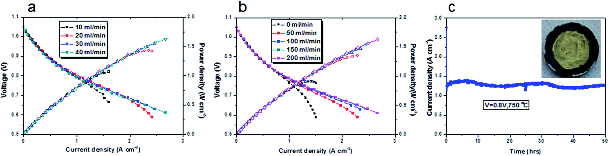 | ||
| Fig. 4 Electrochemical performance of the cell with a structure of BCZYYb-0.6 wt%-Ni-YSZ/YSZ/GDC/LSCF-GDC. (a) Influence of biogas flow rate on the cell performance at 750 °C, a 200 ml min−1 air supplied at the cathode; (b) influence of cathode flow rate on the cell performance at 750 °C, 40 ml min−1 biogas supplied at the anode; (c) durability of the cell tested at 750 °C with a 20 ml min−1 biogas flow at the anode and a 200 ml min−1 air flow at the cathode, operational voltage was 0.8 V, an image of the cell after test is inserted in the graph. | ||
We attributed the high power generation to a well-designed cell structure and selected components. In the presence of BCZYYb, apart from oxygen ions transportation, proton transportation played a role as well. The complex reactions of dry reforming, steam reforming and water-gas shift reactions at the anodes were promoted by the BCZYYb. The cathode response measured in a three-electrode mode of this cell, shown in Fig. S3,† indicated the cell performance could be improved by using other cathode in the future work.
The influence of the cathode air flow rate on the cell performance was investigated and the results are shown in Fig. 4b. Different flow rates, 0, 50, 100, 150, 200 ml min−1 were applied. The air flow rate at the cathode had significant influence on the cell performance, in particular at a high current density. The cell displays oxygen starvation when there was no air flow at the cathode. In this study, a 200 ml min−1 air supply was used to ensure enough air supply at the cathode. At 750 °C, the cell generated a current of 2.2 A cm−2 when the voltage was 0.65 V. At a fuel cell's operational voltage (generally a hydrogen fuel cell operates 0.7 V), a current of 1.67 A cm−2 was obtained. It showed better performance at 850 °C (Fig. S4†), a current of 2.2 A cm−2 was achieved at 0.8 V. To our best knowledge, these high current densities with biogas fuel were not previously reported in the literature. The maximum power densities in biogas were comparable to those in pure hydrogen, wet hydrogen and steam hydrogen (Fig. S4†). The main difference was seen in the OCV values of each gas (Fig. S5, S6 and S7†). The OCV of the cells will be discussed in Section 3.4.1. The maximum power density of the cell with a 20 ml min−1 biogas at 750 °C was 1.43 W cm−2, as shown in Fig. 4a. From Fig. 4b, in some cases we cannot identify the maximum power densities, because of the maximum current limitation of the current source (2.5 (A)). From a rough linear extrapolation, the maximum power density could be ∼1.9 W cm−2 at 750 °C supplied with 200 ml min−1 air to the cathode.
It seemed that the cells were stable over a wide temperature range and at different current densities (0.1 A cm−2, 0.5 A cm−2 and 1 A cm−2, Fig. S8†). The durability of the cell at 750 °C was examined as shown in Fig. 4c. The current density was 1.25 A cm−2 at 0.8 V. The cell was stable for 50 hours with slight fluctuation during the day being possibly due to changes in room temperature and hence actual furnace temperature. The current–voltage curves were collected at a flow rate of 20 ml min−1 biogas. This appeared to be the optimal flow rate, since any further increase, produced no significant improvement in the cell performance (Fig. 4a), but wasted fuel. From Table 1, we can see that the fuel utilisation was 31.2% if the current was 1.25 A (the active area was 1 cm2). Of course, high fuel utilisation can be obtained if the cell is operating at higher current density. An image of this cell after this test inserted in Fig. 4c shows no any obvious carbon deposition was found after operation for 50 hours at 750 °C.
3.4. Reaction mechanism
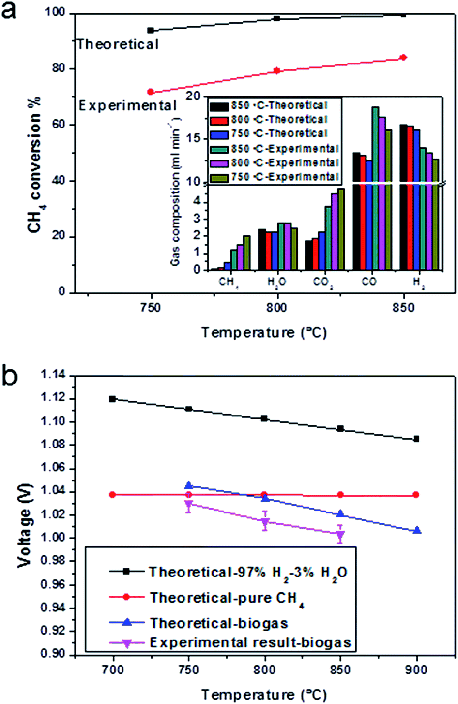 | ||
| Fig. 5 Conversion rate of CH4 and open circuit voltages. (a) Experimental results and theoretical calculation of CH4 conversion rate, insert graph is the anode exhaust gas of the cell with a configuration of BCZYYb-0.6 wt%/Ni-YSZ/YSZ/GDC/LSCF-GDC operating at various temperatures in open-circuit conditions supplied with a 20 ml min−1 biogas. For comparison, theoretical gas compositions were also plotted; (b) experimental results of open circuit voltages with the recirculated biogas as the fuel and theoretical open-circuit voltages with 97%H2, pure CH4 and theoretical equilibrium biogas, were used as the fuel (assuming hydrogen is only oxidised in biogas). | ||
The open-circuit voltage of the cell operating in wet hydrogen at 850 °C was 1.13 V (Fig. S5†), which was close to theoretical value of 1.15 V, showing that the YSZ membrane was gas tight. The OCV changed to 1.06 V when the pure hydrogen was humidified (Fig. S6†). When the gas was changed into 20% steam in hydrogen, the OCV decreased to 0.97 V (Fig. S7†), which was close to the theoretical value of 0.99 V. The open-circuit voltages in the biogas at 850, 800 and 750 °C were 1.00 V, 1.01 V and 1.03 V, respectively (Fig. 5b, pink line), which matched well with the EMFs in theory in Fig. 5b (blue line). Along with the theoretical OCV values in the biogas at different temperatures, the theoretical OCV values using H2 or CH4 as fuel were plotted against temperature. The calculation was done, assuming the H2 or CH4 to be directly oxidised. If the dominant reaction was the oxidation of CH4, there would be no significant change of OCV with temperature (Fig. 5b, red line). The experimental open-circuit voltage increased with the decrease in testing temperature, showing that hydrogen was the primary reactant, since the OCV of a hydrogen-fuelled cell increases with the decreasing temperature (Fig. 5b, black line).
| H2 + 2O2− → H2O + 4e− | (4) |
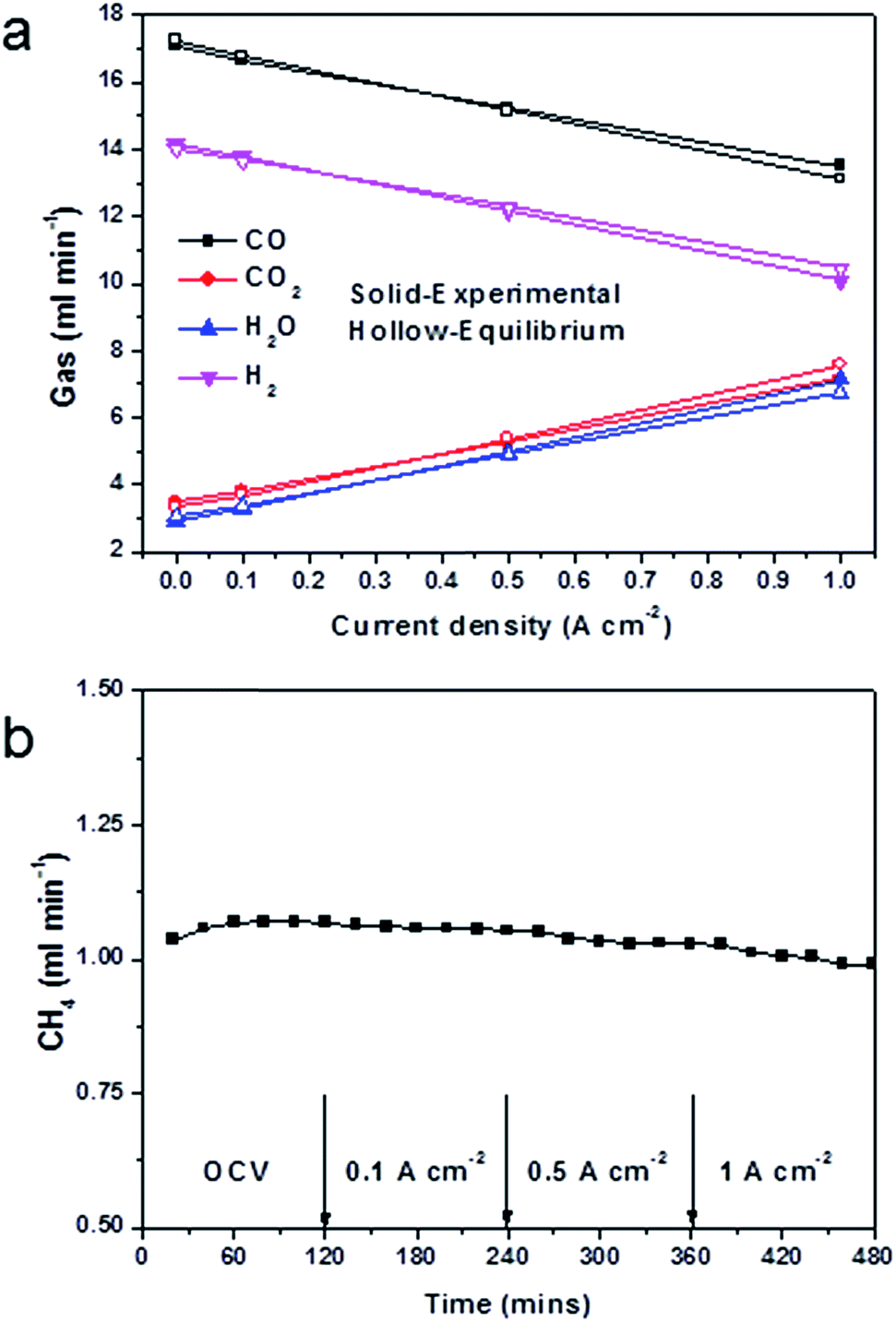 | ||
| Fig. 6 Anode gas compositions and CH4 content of a cell at 850 °C under current load. (a) Experimental results of gas compositions at different current densities supplied with a 20 ml min−1 biogas, for comparison, theoretical equilibrium gas compositions were also included; (b) CH4 content in different conditions, test lasted for 2 hours for each condition. | ||
Similarly, carbon dioxide increased and carbon monoxide decreased with any increase in the current level. This indicated that carbon monoxide was being oxidised into carbon dioxide by a reaction with H2O producing CO2 and H2 (eqn (3)), with the hydrogen being further oxidised into H2O.
The anode exhaust gas composition also showed that gas almost reached equilibrium in most cases, which suggested excellent water-gas shift domination. The only deviation from equilibrium was observed at high current (i.e. 1 A cm−2). At 1 A cm−2, 3.4 ml min−1 CO2 and 4.2 ml min−1 H2O produced, which were the theoretical products for this current (the active cathode area is 1 cm2). With an increase in the current, there was more H2O produced than CO2. This indicated that as more oxygen was driven to oxidise hydrogen, the oxidation of hydrogen exceeded the rate of catalytic water-gas shift. Therefore the water-gas shift deviated from equilibrium. The gas utilisation obtained Fig. 6a was 24.3%, which was close to the theoretical value list in Table 1.
The CH4 content remained at the same level, during the test period, slightly changed with cell configurations and components and current load (Fig. 6b). This indicated that CH4 had mostly reformed in open-circuit conditions, and that direct oxidation of CH4 was not a prevalent reaction. This was in consistent with the OCV results in Fig. 5b. At current load, more products of CO2 and H2O promoted the dry reforming and steam reforming reactions, therefore less CH4 was found. It had been shown in the literature, that the conversion rate of methane increased with the S/C ratio, and that with a S/C ratio of 0.5 the methane conversion was 32%.51 The result in this research, however, showed only 1 ml min−1 of methane in all products, which would indicate that most of the methane had been reformed into hydrogen and carbon monoxide. It should, nevertheless, be noticed that the S/C ratio was only 0.55, and this value was much lower than the required steam amount in a single steam reforming system. This suggested that the participation of carbon dioxide in the reforming reaction was very effective.
4. Conclusions
In this study, an anode recirculation method was used to develop a biogas derived from an original composition of 63% CH4 and 37% CO2, which was prone to carbon coking in the fuel cell operational temperatures. It was shown that anode recirculation was an effective route to use steam and CO2 to obtain a coking free biogas. The biogas used in this study was composed of 36% CH4, 36% CO2, 20% H2O, 4% H2 and 4% CO. Nickel-based solid oxide fuel cells was well-designed and the results showed that nickel anode was able to operate directly in this biogas directly at various temperatures and current densities without carbon deposition. We further developed a new anode structure of a BaZr0.1Ce0.7Y0.1Yb0.1O3−δ (BCZYYb)-Ni-YSZ and the cell with infiltrated anodes had a much better performance at 850 °C, 800 °C and 750 °C. With a 20 ml min−1 biogas supply at the anode and a 200 ml min−1 air supply at the cathode, the highest power density of 1.43 W cm−2 at 750 °C was attained on a cell with a configuration of BCZYYB-Ni-YSZ/YSZ (3 μm)/Gd0.1Ce0.9O2/La0.6Sr0.4Co0.2Fe0.8O3–Gd0.1Ce0.9O2. This cell was able to operate in biogas for 50 hours without degradation. The utilisation of an anode exhaust gas (25% in this study) to achieve the necessary internal reformation increased the system efficiency and fuel utilisation.Acknowledgements
We would like to thank the EPSRC-DST India-UK Collaborative Research Initiative in Fuel Cells project EPI037016/1 “Advancing Biogas through Fuel Flexible SOFC” for funding this work. JI acknowledges the Royal Society for a Wolfson merit award.References
- C. C. Xu, J. W. Zondlo, M. Y. Gong, X. B. Liu and I. B. Celik, Proceedings of the Asme 8th International Conference on Fuel Cell Science, Engineering, and Technology 2010, 2010, vol. 1, pp. 233–241 Search PubMed.
- J. D. Huang and R. J. Crookes, Fuel, 1998, 77, 1793–1801 CrossRef CAS.
- S. Wongchanapai, H. Iwai, M. Saito and H. Yoshida, J. Power Sources, 2013, 223, 9–17 CrossRef CAS PubMed.
- S. T. Naumann and C. Myrén, J. Power Sources, 1995, 56, 45–49 CrossRef.
- J. Staniforth and K. Kendall, J. Power Sources, 1998, 71, 275–277 CrossRef CAS.
- J. van herle, F. Marechal, S. Leuenberger, Y. Membrez, O. Bucheli and D. Favrat, J. Power Sources, 2004, 131, 127–141 CrossRef CAS PubMed.
- R. Peters, R. Dahl, U. Kluttgen, C. Palm and D. Stolten, J. Power Sources, 2002, 106, 238–244 CrossRef CAS.
- K. Sasaki, K. Watanabe, K. Shiosaki, K. Susuki and Y. Teraoka, J. Electroceram., 2004, 13, 669–675 CrossRef CAS.
- A. Lanzini and P. Leone, Int. J. Hydrogen Energy, 2010, 35, 2463–2476 CrossRef CAS PubMed.
- C. Guerra, A. Lanzini, P. Leone, M. Santarelli and N. P. Brandon, J. Power Sources, 2014, 245, 154–163 CrossRef CAS PubMed.
- P. Aguiar, D. Chadwick and L. Kershenbaum, Chem. Eng. Sci., 2002, 57, 1665–1677 CrossRef CAS.
- S. H. Clarke, A. L. Dicks, K. Pointon, T. A. Smith and A. Swann, Catal. Today, 1997, 38, 411–423 CrossRef CAS.
- R. J. Gorte, H. Kim and J. M. Vohs, J. Power Sources, 2002, 106, 10–15 CrossRef CAS.
- S. W. Tao and J. T. S. Irvine, Nat. Mater., 2003, 2, 320–323 CrossRef CAS PubMed.
- Y. H. Huang, R. I. Dass, Z. L. Xing and J. B. Goodenough, Science, 2006, 312, 254–257 CrossRef CAS PubMed.
- O. Costa-Nunes, J. M. Vohs and R. J. Gorte, J. Electrochem. Soc., 2003, 150, A858–A863 CrossRef CAS PubMed.
- M. A. Gerber, Review of Novel Catalysts for Biomass Tar Cracking and Methane Reforming, PNNL-16950, Pacific Northwest National Laboratory, Richland, WA, 2007 Search PubMed.
- D. Qin and J. Lapszewicz, Catal. Today, 1994, 21, 551–560 CrossRef CAS.
- A. Erdohelyi, J. Cserenyi and F. Solymosi, J. Catal., 1993, 141, 287–299 CrossRef CAS.
- M. F. Mark and W. F. Maier, J. Catal., 1996, 164, 122–130 CrossRef CAS.
- E. S. Putna, J. Stubenrauch, J. M. Vohs and R. J. Gorte, Langmuir, 1995, 11, 4832–4837 CrossRef CAS.
- T. Takeguchi, R. Kikuchi, T. Yano, K. Eguchi and K. Murata, Catal. Today, 2003, 84, 217–222 CrossRef CAS.
- C. M. Finnerty, N. J. Coe, R. H. Cunningham and R. M. Ormerod, Catal. Today, 1998, 46, 137–145 CrossRef CAS.
- Y. Kim, J. H. Kim, J. Bae, C. W. Yoon and S. W. Nam, J. Phys. Chem. C, 2012, 116, 13281–13288 CAS.
- T. Papadam, G. Goula and I. V. Yentekakis, Int. J. Hydrogen Energy, 2012, 37, 16680–16685 CrossRef CAS PubMed.
- A. Hagen, J. F. B. Rasmussen and K. Thydén, J. Power Sources, 2011, 196, 7271–7276 CrossRef CAS PubMed.
- Y. Shiratori and K. Sasaki, J. Power Sources, 2008, 180, 738–741 CrossRef CAS PubMed.
- D. Saebea, Y. Patcharavorachot and A. Arpornwichanop, J. Power Sources, 2012, 208, 120–130 CrossRef CAS PubMed.
- V. Liso, A. C. Olesen, M. P. Nielsen and S. K. Kaer, Energy, 2011, 36, 4216–4226 CrossRef CAS PubMed.
- G. Goula, V. Kiousis, L. Nalbandian and I. V. Yentekakis, Solid State Ionics, 2006, 177, 2119–2123 CrossRef CAS PubMed.
- H. D. A. L. Viana and J. T. S. Irvine, Solid State Ionics, 2007, 178, 717–722 CrossRef CAS PubMed.
- K. S. Blinn and M. L. Liu, J. Power Sources, 2013, 243, 24–28 CrossRef CAS PubMed.
- S. M. Fang, L. Bi, C. L. Yang, L. T. Yan, C. S. Chen and W. Liu, J. Alloys Compd., 2009, 475, 935–939 CrossRef CAS PubMed.
- L. Yang, S. Z. Wang, K. Blinn, M. F. Liu, Z. Liu, Z. Cheng and M. L. Liu, Science, 2009, 326, 126–129 CrossRef CAS PubMed.
- I. Luisetto, E. di Bartolomeo, A. D'Epifanio and S. Licoccia, J. Electrochem. Soc., 2011, 158, B1368–B1372 CrossRef CAS PubMed.
- F. Wang, W. Wang, R. Ran, M. O. Tade and Z. Shao, J. Power Sources, 2014, 268, 787–793 CrossRef CAS PubMed.
- C. Xia and M. Liu, Solid State Ionics, 2002, 152–153, 423–430 CrossRef CAS.
- T. Tsai and S. A. Barnett, Solid State Ionics, 1997, 98, 191–196 CrossRef CAS.
- C. Xia, F. Chen and M. Liu, Electrochem. Solid-State Lett., 2001, 4, A52–A54 CrossRef CAS PubMed.
- T. Tsai and S. A. Barnett, Solid State Ionics, 1997, 93, 207–217 CrossRef CAS.
- Y. J. Leng, S. H. Chan, K. A. Khor and S. P. Jiang, Int. J. Hydrogen Energy, 2004, 29, 1025–1033 CrossRef CAS PubMed.
- C. S. Ding and T. Hashida, Energy Environ. Sci., 2010, 3, 1729–1731 CAS.
- K. Sasaki and Y. Teraoka, J. Electrochem. Soc., 2003, 150, A878–A884 CrossRef CAS PubMed.
- M. Powell, K. Meinhardt, V. Sprenkle, L. Chick and G. McVay, J. Power Sources, 2012, 205, 377–384 CrossRef CAS PubMed.
- S. R. Gamble, D. Neagu and J. T. S. Irvine, ECS Trans., 2013, 57, 1527–1532 CrossRef PubMed.
- C. R. Jiang, J. J. Ma, A. D. Bonaccorso and J. T. S. Irvine, Energy Environ. Sci., 2012, 5, 6973–6980 CAS.
- F. Han, R. Muecke, T. van Gestel, A. Leonide, N. H. Menzler, H. P. Buchkremer and D. Stover, J. Power Sources, 2012, 218, 157–162 CrossRef CAS PubMed.
- S. deSouza, S. J. Visco and L. C. de Jonghe, J. Electrochem. Soc., 1997, 144, L35–L37 CrossRef CAS PubMed.
- S. P. Jiang, Mater. Sci. Eng., A, 2006, 418, 199–210 CrossRef PubMed.
- A. Hauch, M. Mogensen and A. Hagen, Solid State Ionics, 2011, 192, 547–551 CrossRef CAS PubMed.
- D. H. Prasad, H. I. Ji, H. R. Kim, J. W. Son, B. K. Kim, H. W. Lee and J. H. Lee, Appl. Catal., B, 2011, 101, 531–539 CrossRef CAS PubMed.
Footnotes |
| † Electronic supplementary information (ESI) available. See DOI: 10.1039/c5ta06421j |
| ‡ The research data supporting this publication can be accessed at http://dx.doi.org/10.17630/408942b8-b397-41ef-a932-ffc3bc6ced49 |
| § These authors contributed equally to this work. |
| This journal is © The Royal Society of Chemistry 2015 |