Crosslinked poly(phenylene oxide)-based nanofiber composite membranes for alkaline fuel cells†
Andrew M.
Park
a,
Ryszard J.
Wycisk
a,
Xiaoming
Ren
b,
Forbes E.
Turley
a and
Peter N.
Pintauro
*a
aDepartment of Chemical and Biomolecular Engineering, Vanderbilt University, Nashville, Tennessee 37235, USA. E-mail: peter.pintauro@vanderbilt.edu
bU.S. Army Research Laboratory 2800 Powder Mill Rd. RDRL-SED-C, Adelphi, MD 20783, USA
First published on 17th November 2015
Abstract
Anion exchange membranes were fabricated from diamine-crosslinked poly(phenylene oxide) polyelectrolyte nanofibers that were functionalized with either benzyl trimethylammonium or 1,2-dimethylimidazolium groups and embedded in a reinforcing matrix of polyphenylsulfone (PPSU). Nanofibers of the polyelectrolyte precursor, brominated poly(phenylene oxide) with 0.95 CH2Br groups per mer, and PPSU were simultaneously electrospun onto a common collector and the resulting dual fiber mat was converted into a dense and defect-free anion exchange membrane by sequential soaking in a diamine crosslinker solution, exposure to chloroform vapor, and immersion in a solution of either trimethylamine or 1,2-dimethylimidazole. The degree of crosslinking and the ratio of uncharged PPSU to functionalized poly(phenylene oxide) polyelectrolyte were varied to yield composite membranes with an effective ion exchange capacity (IEC) ranging from 1.2–2.8 mmol g−1. A membrane with benzyl trimethylammonium-functionalized polyelectrolyte fibers (4.0 mmol g−1 IEC) with 15% crosslinks and 50 wt% uncharged PPSU exhibited a high hydroxide ion conductivity in water at 23 °C (66 mS cm−1), reasonable water swelling (96%), robust mechanical properties (15 MPa stress-at-break in the hydrated state), and good chemical stability in 1.0 M KOH at 60 °C. Initial hydrogen/oxygen fuel cell tests with this membrane (40 μm thick) were promising, with a peak power density of 320 mW cm−2.
Introduction
There has been a resurgence of interest in alkaline fuel cells recently, which has reinvigorated efforts to develop new anion exchange type solid polymer electrolyte membranes.1 The anion exchange membrane fuel cell (AEMFC) is an attractive alternative to the more commonly studied proton exchange membrane fuel cell (PEMFC), because inexpensive non-platinum group metals, such as nickel or silver, can be used as the electrode materials.2 The polymeric membrane in an AEMFC generally comprises cationic fixed charge functional groups (e.g., benzyl trimethylammonium moieties) tethered to a polymer backbone.3 To be suitable for fuel cell applications, such membranes must have a high hydroxide ion conductivity, robust mechanical properties in both the wet and dry states, and good chemical stability in an elevated temperature alkaline environment.4To achieve good hydroxide ion conductivity, researchers generally employ a membrane with a high concentration of fixed charge cationic groups, typically expressed as the membrane's ion exchange capacity (IEC, with units of mmol g−1 of dry polymer). A variety of tactics have been employed to avoid excessive water swelling and improve the mechanical properties of high IEC anion exchange membranes, including the use of hydrophobic/hydrophilic block co-polymers,5 polyelectrolyte crosslinking,6,7 and composite morphologies where a polyelectrolyte is impregnated into a porous uncharged reinforcing polymer matrix.8 Several research groups have fabricated AEMs with a hydroxide ion conductivity close to the H+ conductivity of Nafion, the standard membrane for a PEMFC.6,9–11
The chemical stability of AEMs is another topic that has been more closely studied in recent years. Many polymers, such as quaternary ammonium functionalized polysulfones, are prone to charged group degradation and main chain scission by nucleophilic hydroxide ion attack.12,13 Membranes based on poly(phenylene oxide) (henceforth abbreviated as PPO) appear to survive longer in strong alkaline media due to slower degradation reactions14,15 and thus are good candidate materials for use in an AEM. There have been numerous studies on PPO-based AEMs7,16–20 for AEMFCs, but most were not focused on chemical stability. For example, Arges et al.21 prepared benzyl trimethylammonium PPO AEMs with 2.1 mmol g−1 IEC and found a hydroxide ion conductivity of 40 mS cm−1 for membranes immersed in water at 23 °C. In membrane-electrode-assemblies (MEAs) with the same PPO as an electrode binder, a maximum fuel cell power density of 292 mW cm−2 was observed at 60 °C with Pt/C catalyst in the anode and cathode. In another study, Li et al.7 reported on olefin-crosslinked PPO anion exchange membranes with benzyl 1-hexyl-2,3-dimethylammonium fixed charges where the IEC was very high (3.2 mmol g−1), the chemical stability was excellent (essentially no loss in IEC over 500 hours in 1.0 M KOH at 80 °C), and the hydroxide ion conductivity was reasonably high at 40 mS cm−1.
Another technique for fabricating composite membranes, developed by Ballengee and Pintauro,27 involves dual fiber electrospinning, where charged and uncharged polymer nanofibers are simultaneously deposited onto a collector surface followed by processing the dual fiber mat into a dense and defect-free membrane. When applied to proton conducting fuel cells, two different membrane morphologies can be created from the same dual fiber mat: (1) an interconnecting network of ionomer fibers embedded in an uncharged polymer matrix, and (2) a network of electrospun uncharged reinforcing polymer nanofibers that is surrounded by an ionomer matrix. More recently, Park et al.22–24 used a dual fiber electrospinning approach to prepare a variety of AEMs, where a nanofiber mat of crosslinked hydroxide ion conducting polysulfone-based polyelectrolyte fibers was embedded in an uncharged polyphenylsulfone matrix. Membranes with 35 wt% reinforcing polyphenylsulfone and diamine- or diol-crosslinked polysulfone fibers containing quaternary ammonium fixed charges (at a high IEC of ∼3.0 mmol g−1) were insoluble in liquid water, highly conductive (an OH− ion conductivity as high as 65 mS cm−1 in water at room temperature), and mechanically robust in the wet and dry states.
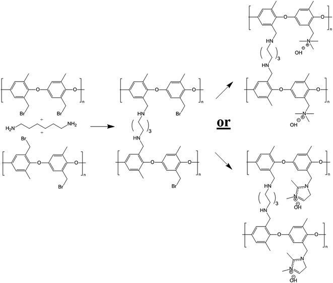
The present paper is the latest installment of ongoing research into the fabrication and characterization of nanofiber composite AEMs. Here, the final membrane is composed of an interconnected network of diamine-crosslinked poly(phenylene oxide) fibers with either benzyl trimethylammonium or benzyl 1,2-dimethylimidazoium fixed charge sites. The polyelectrolyte fiber mat is embedded in an uncharged polyphenylsulfone matrix. Membranes were prepared by simultaneously electrospinning brominated PPO and polyphenylsulfone to form a dual fiber mat. The mat was then soaked in a hexamethylenediamine solution to create a small number of crosslinks in the PPO fibers (preventing water solubility when charged groups were added to the PPO), as shown in Fig. 1. Subsequent mat processing included mechanical compaction, exposure to chloroform vapor (which softened the polyphenylsulfone, allowing it to flow and fill the void space between crosslinked brominated PPO fibers), and reaction of the resulting films with either trimethylamine or 1,2-dimethylimidazole to create cationic groups at those bromomethyl sites of PPO which did not react with diamine crosslinker.
The objective of this report is to investigate the complex interplay between chemical structure (i.e., diamine crosslinks and ion exchange capacity) and nanomorphology (i.e., polyelectrolyte/uncharged reinforcement ratio), and their effects on membrane performance. A series of nanofiber composite anion exchange membranes were thus tested for hydroxide ion conductivity, gravimetric water uptake, mechanical properties in the wet and dry states, and chemical stability in hot KOH. The most conductive and stable membrane was converted into a fuel cell membrane-electrode-assembly and tested in an alkaline fuel cell at 60 °C with H2 and O2 feed gases.
Experimental
Materials
Poly(2,6-dimethyl-1,4-phenylene oxide) (PPO, MW = 30![[thin space (1/6-em)]](https://www.rsc.org/images/entities/char_2009.gif) 000 g mol−1) was purchased from Sigma Aldrich and dried overnight at 70 °C. Radel® polyphenylsulfone (henceforth abbreviated as PPSU, MW = 63
000 g mol−1) was purchased from Sigma Aldrich and dried overnight at 70 °C. Radel® polyphenylsulfone (henceforth abbreviated as PPSU, MW = 63![[thin space (1/6-em)]](https://www.rsc.org/images/entities/char_2009.gif) 000 g mol−1) was obtained from Solvay Advanced Polymers, LLC and dried at 140 °C for 2 h. Bromine, chlorobenzene, dimethylacetamide (DMAc), methanol, acetone, N-methyl-2-pyrrolidinone (NMP), 60 wt% aqueous hexamethylenediamine solution, 50 wt% aqueous trimethylamine solution, 1,2-dimethylimidazole, and chloroform were used as received from Sigma Aldrich or Fisher Scientific.
000 g mol−1) was obtained from Solvay Advanced Polymers, LLC and dried at 140 °C for 2 h. Bromine, chlorobenzene, dimethylacetamide (DMAc), methanol, acetone, N-methyl-2-pyrrolidinone (NMP), 60 wt% aqueous hexamethylenediamine solution, 50 wt% aqueous trimethylamine solution, 1,2-dimethylimidazole, and chloroform were used as received from Sigma Aldrich or Fisher Scientific.
Synthesis of brominated PPO
Bromination of the methyl side groups of PPO polymer was performed according to the procedure published by Xu and co-workers.25 15 g of dried PPO was dissolved in chlorobenzene at 8% w/v and heated to boiling (∼132 °C) under reflux. In a separate flask, liquid bromine (Br2) was mixed with chlorobenzene at a 1![[thin space (1/6-em)]](https://www.rsc.org/images/entities/char_2009.gif) :
:![[thin space (1/6-em)]](https://www.rsc.org/images/entities/char_2009.gif) 3 wt ratio (the amount of liquid bromine varied depending on the desired amount of benzyl bromination). This mixture was added drop wise (∼1 drop/5 seconds) to the PPO/chlorobenzene solution. After addition, the mixture was stirred at 132 °C for 1.5 h. The brominated PPO was precipitated in ethanol at a 5
3 wt ratio (the amount of liquid bromine varied depending on the desired amount of benzyl bromination). This mixture was added drop wise (∼1 drop/5 seconds) to the PPO/chlorobenzene solution. After addition, the mixture was stirred at 132 °C for 1.5 h. The brominated PPO was precipitated in ethanol at a 5![[thin space (1/6-em)]](https://www.rsc.org/images/entities/char_2009.gif) :
:![[thin space (1/6-em)]](https://www.rsc.org/images/entities/char_2009.gif) 1 v/v ethanol/PPO solution ratio. The degree of bromination was determined by 1H NMR.
1 v/v ethanol/PPO solution ratio. The degree of bromination was determined by 1H NMR.
Electrospinning
Brominated PPO (BrPPO) and polyphenylsulfone were separately and simultaneously electrospun into a dual fiber mat, where fibers of each polymer were randomly distributed on a rotating and laterally oscillating drum collector. PPSU was chosen as the uncharged component because it has good mechanical properties and excellent alkaline stability (it does not undergo hydrolysis at the ether linkage in the backbone because there are no tethered fixed charge groups).12 It was successfully used as the uncharged reinforcement in other nanofiber composite proton exchange membranes and AEMs.26,27Table 1 lists the electrospinning conditions for the two polymers. The flow rate of BrPPO was held constant for all electrospun mats, whereas the flow rate of PPSU was either 0.2 mL h−1 or 0.32 mL h−1, to give a final membrane with either 35 wt% or 50 wt% PPSU, respectively. Temperature and humidity during electrospinning were controlled at 23 °C and 35% RH, respectively. The PPSU content of a given mat was confirmed by dissolution in CDCL3 and analysis by 1H NMR.| Polymer | Polymer concentration (w/w) | Applied voltage (kV) | Flow rate (mL h−1) | Spinneret/collector distance (cm) |
|---|---|---|---|---|
| PPSU | 25 (in 4![[thin space (1/6-em)]](https://www.rsc.org/images/entities/char_2009.gif) : :![[thin space (1/6-em)]](https://www.rsc.org/images/entities/char_2009.gif) 1 wt ratio NMP/acetone) 1 wt ratio NMP/acetone) |
+9 | 0.2 or 0.32 | 9 |
| BrPPO | 30 (in NMP) | +12 | 0.3 | 9 |
Membrane fabrication
The as-spun dual fiber mats had a fiber volume fraction of ∼0.2. Samples from these mats were immersed for 5–60 minutes in a solution of hexamethylenediamine (0.2 wt% in DMAc) to partially crosslink the BrPPO polymer fibers, where the degree of crosslinking increased with immersion time. PPSU fibers were not affected by this soaking step. After removal from the crosslinking solution, the mats were washed in DI water, dried, and compressed at 5000 psi for ∼20 seconds to increase the fiber volume fraction to ∼0.7. These mats were then densified by exposure to chloroform vapor at 23 °C, during which time PPSU softened and flowed to fill the void space between crosslinked BrPPO fibers. Excess chloroform was evaporated by heating the dense membranes at 70 °C for 1 hour. To convert the remaining bromomethyl groups to anion exchange sites, the composite films were soaked in a solution of free base at 40 °C for 16 hours, either trimethylamine (a 50 wt% aqueous solution) or 1,2-dimethylimidazole (a 45 wt% solution in methanol). The final membranes, with either benzyl trimethylammonium or 1,2-dimethylimidazolium cationic groups and Br− counterions, were stored in water until further use. Before a characterization experiment, the membranes were converted to the hydroxide counterion form by soaking in 1.0 M KOH at 23 °C for 2 hours followed by a through washing with degassed DI water.Membrane characterization
1H NMR measurements were taken on a Bruker 401 or 501 MHz spectrometer where samples were dissolved in either CDCL3 or CD3OD, and analyzed by Topspin software. Images of the dual fiber mats and composite membranes were recorded by a Hitachi S-4200 scanning electron microscope (SEM). A thin layer of gold was deposited on samples with a Cressington sputter coater to minimize sample charging during scanning. The average fiber diameter in a SEM image of an electrospun mat was determined using ImageJ software. Mechanical properties of membrane samples (in the chloride counterion form) were evaluated using a TA Instruments Q800 dynamic mechanical analyzer fitted with a tension clamp at the strain rate of 30% min−1. Wet samples were equilibrated in water and patted dry just before testing; dry samples were equilibrated in air for 24 h at 20% RH.The percent gravimetric swelling, the volumetric concentration of fixed charge groups in polyelectrolyte fibers (χ, mmol cm−3 water), and the in-plane hydroxide ion conductivity were determined at room temperature using methods described previously,22 where
 | (1) |
 | (2) |
 | (3) |
In the above equations, Wwet is the weight [g] of a membrane sample after equilibration in liquid water, Wdry is the weight [g] of the same sample after drying at 70 °C for 2 hours, IECmem is the measured ion exchange capacity of the composite membrane [based on the total dry weight of polyelectrolyte and PPSU, mmol g−1], ρ is the density of water [g cm−3], σ is the ion conductivity [mS cm−1], L is the distance between working electrodes in the Bekktech AC impedance conductivity cell [cm], R is the resistance of the membrane [Ω], w = measured wet sample width [cm], and δ = measured wet (liquid water equilibrated) membrane thickness [cm].
Membrane IEC was calculated using the Mohr titration method, where all membrane samples (∼0.1 grams in weight) were initially in the chloride counterion form.28,29 Chloride ions were then exchanged for NO3− by soaking membrane samples in 2 separate 20 mL batches of a 0.2 M NaNO3 solution. These solutions were collected (40 mL total) and titrated using 0.01 M AgNO3 with K2CrO4 as the end point indicator. IEC was calculated as the moles of Cl− titrated divided by the dry weight of the membrane sample. For uncrosslinked, water soluble polymers, IEC was determined using 1H NMR after dissolving samples in DMSO-d6.
The chemical stability of composite membranes was assessed by immersing samples in 1.0 M KOH for up to 7 days at 50 °C, 60 °C and 80 °C. Every 24 hours, samples were removed from the soak solution, washed thoroughly with degassed DI water, and tested for in-plane hydroxide ion conductivity. The percentage of initial conductivity retained over time was recorded.
Alkaline fuel cell tests
Membrane-electrode-assemblies (MEAs, with a geometric area of 5 cm2) were fabricated using a high conductivity nanofiber composite membrane, with a wet thickness of either 40 or 90 μm. Electrodes were prepared with either Tokuyama AS-4 ionomer solution (IEC 1.8 mmol g−1) or uncrosslinked benzyl trimethylammonium PPO (2.2 mmol g−1 IEC, which is insoluble in water at temperatures up to 70 °C). Each binder polymer (in the halide form) was mixed with water, methanol, and catalyst (Johnson Matthey Company HiSpec 4000 Pt/C catalyst powder, 40% Pt on carbon black), where the catalyst![[thin space (1/6-em)]](https://www.rsc.org/images/entities/char_2009.gif) :
:![[thin space (1/6-em)]](https://www.rsc.org/images/entities/char_2009.gif) binder ratio was fixed at 3
binder ratio was fixed at 3![[thin space (1/6-em)]](https://www.rsc.org/images/entities/char_2009.gif) :
:![[thin space (1/6-em)]](https://www.rsc.org/images/entities/char_2009.gif) 1 w/w. Mixing was carried out for 20 minutes using a sonication horn. The ink with Tokuyama AS-4 binder was sprayed onto a PTFE film and transferred onto the opposing surfaces of a dry nanofiber composite membrane by the decal method to form a catalyst coated membrane (CCM). The electrode hot-pressing conditions were 105 °C for 6 min under 10
1 w/w. Mixing was carried out for 20 minutes using a sonication horn. The ink with Tokuyama AS-4 binder was sprayed onto a PTFE film and transferred onto the opposing surfaces of a dry nanofiber composite membrane by the decal method to form a catalyst coated membrane (CCM). The electrode hot-pressing conditions were 105 °C for 6 min under 10![[thin space (1/6-em)]](https://www.rsc.org/images/entities/char_2009.gif) 000 pounds force. After hot-pressing, the CCM was re-hydrated in DI water, washed with 1.0 M KOH solution for 2 hours, and rinsed thoroughly with DI water.30 Sigracet 25 BC gas diffusion layers (GDLs) from Ion Power Inc. were pressed onto each electrode in the fuel cell test fixture to create an MEA. For the quaternary ammonium PPO electrode binder, the electrode ink was painted directly onto the Sigracet 25 BC GDLs to form gas diffusion electrodes (GDEs). The GDEs (anode and cathode) and membrane were soaked in 1.0 M KOH, washed thoroughly in DI water, and pressed together in the fuel cell test fixture. The platinum loading for the anode and cathode was 0.5 mgPt cm−2. MEAs were tested in a Scribner Series 850e test station at 60 °C with fully humidified H2 and O2 feed gases at 2 atm backpressure, where the gas flow rates were kept constant at 0.125 L min−1 for H2 and 0.25 L min−1 for O2. MEAs were preconditioned by operating at a constant voltage (0.4 V) for ∼20 minutes, until the current density stabilized, during which time hydroxide counterions replaced bicarbonate ions in the electrode binder and membrane. Polarization data was then collected, where voltage was scanned from 1.0 V to 0.2 V with current measurement at a given voltage after 30 seconds. Hydrogen crossover limiting current was determined in the fuel cell test fixture from a linear sweep voltammetry experiment, where H2 and Ar gases were fed to the anode and cathode, respectively.31 The voltage was varied from 400 mV to ∼20 mV at 1 mV s−1 and the temperature was fixed at 60 °C. Limiting current data in mA cm−2 were converted to a hydrogen crossover flux (corrected for membrane thickness) using eqn (4)
000 pounds force. After hot-pressing, the CCM was re-hydrated in DI water, washed with 1.0 M KOH solution for 2 hours, and rinsed thoroughly with DI water.30 Sigracet 25 BC gas diffusion layers (GDLs) from Ion Power Inc. were pressed onto each electrode in the fuel cell test fixture to create an MEA. For the quaternary ammonium PPO electrode binder, the electrode ink was painted directly onto the Sigracet 25 BC GDLs to form gas diffusion electrodes (GDEs). The GDEs (anode and cathode) and membrane were soaked in 1.0 M KOH, washed thoroughly in DI water, and pressed together in the fuel cell test fixture. The platinum loading for the anode and cathode was 0.5 mgPt cm−2. MEAs were tested in a Scribner Series 850e test station at 60 °C with fully humidified H2 and O2 feed gases at 2 atm backpressure, where the gas flow rates were kept constant at 0.125 L min−1 for H2 and 0.25 L min−1 for O2. MEAs were preconditioned by operating at a constant voltage (0.4 V) for ∼20 minutes, until the current density stabilized, during which time hydroxide counterions replaced bicarbonate ions in the electrode binder and membrane. Polarization data was then collected, where voltage was scanned from 1.0 V to 0.2 V with current measurement at a given voltage after 30 seconds. Hydrogen crossover limiting current was determined in the fuel cell test fixture from a linear sweep voltammetry experiment, where H2 and Ar gases were fed to the anode and cathode, respectively.31 The voltage was varied from 400 mV to ∼20 mV at 1 mV s−1 and the temperature was fixed at 60 °C. Limiting current data in mA cm−2 were converted to a hydrogen crossover flux (corrected for membrane thickness) using eqn (4) | (4) |
![[thin space (1/6-em)]](https://www.rsc.org/images/entities/char_2009.gif) 485 C mol−1], and δ is membrane thickness [μm]. Crossover current was measured at cell gas pressures ranging from 1 atm (ambient) to 3 atm.
485 C mol−1], and δ is membrane thickness [μm]. Crossover current was measured at cell gas pressures ranging from 1 atm (ambient) to 3 atm.
Results and discussion
Membrane fabrication
Poly(phenylene oxide) (PPO) was successfully brominated at the benzyl position to give brominated poly(phenylene oxide) (abbreviated as BrPPO) as shown in Fig. 1. A representative NMR spectrum of BrPPO is given in Fig. 2. A comparison of the integrals of the CH2Br groups (4.3 ppm) and remaining unfunctionalized CH3 groups (2.1 ppm) gives the average degree of polymer bromination, which was determined to be 0.95 CH2Br groups per mer (assuming all subunits had only one tethered bromine). It is possible that there are some subunits with two benzyl bromine moieties, but this cannot be determined from the 1-D 1H NMR spectrum and would not affect the IEC of the quaternized polymer. From a calculation of the remaining aryl hydrogens on the PPO backbone (at 6.5–7 ppm), along with the lack of peak splitting of the signal at 2.1 ppm, it was concluded that there was essentially no (i.e., <2%) aryl backbone bromination (aryl bromine moieties will not react with free base and thus will lower the overall IEC of the polyelectrolyte by increasing the weight of the polymer backbone) and that the sample is well-purified. The near total preference for benzyl bromine substitution matches well with previous work at the same conditions by Xu and Yang.32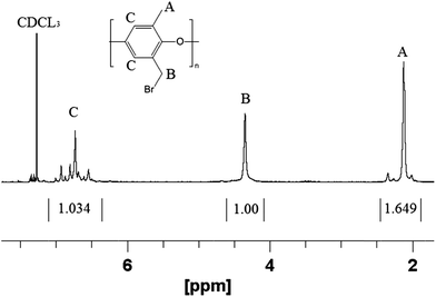 | ||
| Fig. 2 Representative 1H NMR spectrum of brominated PPO precursor with 0.95 degree of functionalization. | ||
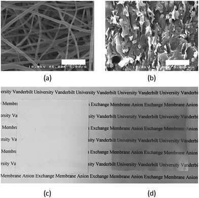
BrPPO polyelectrolyte precursor was simultaneously electrospun with polyphenylsulfone (PPSU) to give a dual fiber mat according to the conditions listed in Table 1. An SEM micrograph of this initial dual fiber mat is shown in Fig. 3a. BrPPO and PPSU fibers are indistinguishable and the average fiber diameter is 400 nm. A SEM cross-section image of the final dense membrane is given in Fig. 3b, after fiber crosslinking, mat compaction, exposure to chloroform, and soaking in free base. Fibers of crosslinked, benzyl trimethylammonium functionalized PPO are visible in the reinforcing matrix of uncharged PPSU, thus the fiber network morphology of the polyelectrolyte is retained during mat processing. Fig. 3c and d present a visual comparison of the initial fiber mat and the final membrane. The fiber mat is opaque due to its high porosity (∼80%), while the final membrane is transparent, qualitatively indicating a fully dense, void free structure. SEMs, density measurements, and hydrogen crossover data (see Fig. 12 below) confirmed that the fiber composite membranes were pinhole-free.
Nanofiber composite membranes were prepared with either 65 wt% or 50 wt% crosslinked polyelectrolyte. The same BrPPO precursor (0.95 degree of bromination assuming only one bromine per subunit) was used in all membranes. Assuming 100% reaction of all CH2Br groups with trimethylamine, this precursor polymer would yield a polyelectrolyte ion exchange capacity (IEC) of 4.92 mmol g−1 in the benzyl trimethylammonium form, nearly double the IEC limit for solubility in water. Consequently, crosslinking of the BrPPO precursor was needed, which was performed by soaking a dual fiber mat in a 0.1 wt% hexamethylenediamine solution for a specified time using the same procedure as that recently published for a chloromethylated polysulfone polyelectrolyte fiber precursor.22 The relationship between soak time and crosslinking degree is shown in Fig. S1 of the ESI.† It should also be noted that no evidence was found for further reaction of the secondary amine crosslink (i.e., tertiary or quaternary ammonium formation), as was the case for the study described in ref. 22. Thus, a series of nanofiber composite membranes were made with an effective IEC (based on the total dry weight of polyelectrolyte and polyphenylsulfone) of between 1.2 and 2.8 mmol g−1 by varying: (1) the amount of polyelectrolyte polymer in the composite membrane (either 65 or 50 wt%), (2) the degree of crosslinking in the polyelectrolyte fiber (10% to 40%), and (3) the choice of functional group tethered to the crosslinked PPO backbone (either benzyl trimethylammonium or 1,2-dimethylimidazolium, with molecular weights of 73 and 110 g mol−1, respectively).
Membrane performance
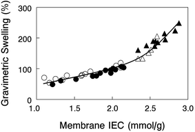
Gravimetric swelling of nanofiber composite membranes at 23 °C in liquid water is shown in Fig. 4 for crosslinked PPO polyelectrolyte fiber membranes with either benzyl trimethylammonium or 1,2-dimethylimidazolium fixed charge cations. Membranes with different amounts of uncharged PPSU (either 35% or 50%) fall on two distinct regions of a swelling vs. IEC plot, low PPSU loaded films (high slope) and high PPSU loading (low slope). The results suggest that membrane swelling is solely a function of the dry polymer IEC and is independent of how that IEC was achieved (through crosslinking, dilution of the polymer electrolyte fibers with PPSU, or changing the molecular weight of the fixed charge site). The results show that 35 wt% PPSU in a composite membrane is insufficient to adequately control water swelling of the polyelectrolyte fiber (water swelling was between 140 and 250%), whereas 50% PPSU yielded films with moderate/acceptable levels of swelling, in the range of 50–110%.The effect of temperature on in-plane and gravimetric swelling of one nanofiber composite membrane is presented as Table S1 in the ESI.†
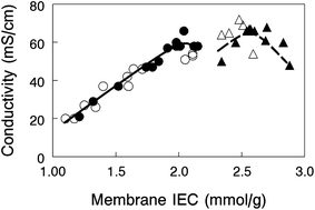
In-plane hydroxide ion conductivity of nanofiber composite membranes equilibrated in liquid water at 23 °C is plotted in Fig. 5 as a function of membrane IEC for films with 35 or 50 wt% PPSU and either benzyl trimethylammonium or 1,2-dimethylimidazolium functional groups. Conductivity is independent of the fixed charge group chemistry, but unlike water swelling, there appears to be two distinct conductivity vs. IEC curves for membranes with 35 wt% and 50 wt% PPSU. Membranes with a greater loading of PPSU (50 wt%) have fewer polyelectrolyte fibers which lowers the cross-sectional area available for ion transport and makes the fibers more tortuous. Despite these seemingly unwanted effects, composite membranes with benzyl trimethylammonium fixed charges yielded a very high OH− ion conductivity (66 mS cm−1 for 50 wt% PPSU at an IEC of 2.0 mmol g−1), essentially the same as that obtained with a 35 wt% PPSU film (68 mS cm−1) at a much higher effective membrane IEC (2.7 mmol g−1 IEC).
In order to better explain the behavior and properties of water swollen ion exchange membranes, we utilize a wet membrane volume-based polyelectrolyte fixed charge concentration instead of the IEC (which is based on the dry membrane weight). This new parameter, χ, with units of mmol charge per cm3 sorbed water, is related to the IEC by eqn (2). χ has been used previously to analyze the properties of polysulfone-based AEMs because it is a more representative measure of the actual concentration of fixed charges in a functioning (i.e., hydrated) membrane.33 It should also be noted that χ is inversely proportional to the λ parameter (the number of water molecules per ion exchange site, which is often used in the description/analysis of proton exchange membranes), according to eqn (5)
 | (5) |
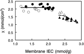
![[V with combining macron]](https://www.rsc.org/images/entities/i_char_0056_0304.gif) is the molar volume of water. As can be seen in Fig. 6, membranes with 35 wt% PPSU content, which have the highest effective membrane IEC on a dry gram basis, possess low values of χ, i.e., excessive membrane water uptake dilutes the high concentration fixed charges. When the uncharged PPSU content in nanofiber composite membranes is increased from 35 to 50 wt%, the χ values increase to ∼2.1 mmol cm−3, even though the effective dry membrane IEC, which is based on the total weight of polyelectrolyte fibers and uncharged polymer, has been substantially reduced. The high and near constant χ value of the 50 wt% PPSU membranes of different dry polymer IEC (where differences in IEC are due to different degrees of PPO crosslinking) suggests that increasing PPSU content is more effective than polyelectrolyte fiber crosslinking for decreasing membrane swelling. Thus, to maximize conductivity, one should add the minimum number of crosslinks to the polyelectrolyte fibers, in an amount required to stop water dissolution only, and then use the uncharged PPSU component of the nanofiber composite membranes to limit water swelling. From the data in Fig. 6, membranes at an effective membrane IEC of ∼2.0 with 50 wt% PPSU fulfill this criteria.
is the molar volume of water. As can be seen in Fig. 6, membranes with 35 wt% PPSU content, which have the highest effective membrane IEC on a dry gram basis, possess low values of χ, i.e., excessive membrane water uptake dilutes the high concentration fixed charges. When the uncharged PPSU content in nanofiber composite membranes is increased from 35 to 50 wt%, the χ values increase to ∼2.1 mmol cm−3, even though the effective dry membrane IEC, which is based on the total weight of polyelectrolyte fibers and uncharged polymer, has been substantially reduced. The high and near constant χ value of the 50 wt% PPSU membranes of different dry polymer IEC (where differences in IEC are due to different degrees of PPO crosslinking) suggests that increasing PPSU content is more effective than polyelectrolyte fiber crosslinking for decreasing membrane swelling. Thus, to maximize conductivity, one should add the minimum number of crosslinks to the polyelectrolyte fibers, in an amount required to stop water dissolution only, and then use the uncharged PPSU component of the nanofiber composite membranes to limit water swelling. From the data in Fig. 6, membranes at an effective membrane IEC of ∼2.0 with 50 wt% PPSU fulfill this criteria.
From a comparison of the data in Fig. 5 and 6, however, it is obvious that χ alone cannot describe the observed variations in hydroxide ion conductivity (e.g., membranes of constant χ with 50% PPSU have different conductivities). In actuality, ion conductivity in the nanofiber composite films depends not only on χ, but also on the ion mobility within a polyelectrolyte fiber (which will decrease with increasing crosslinking) and the amount of uncharged PPSU in a membrane (which decreases the cross sectional membrane area for ion transport and increases the tortuosity of the polyelectrolyte fiber network). The examination of three membrane data points from Fig. 5 (properties of which are listed in Table 2) is sufficient to illustrate the interdependence of these three effects.
| Effective membrane IEC (mmol g−1) | Polyelectrolyte fiber IEC (mmol g−1) | Composite membrane χ (mmol cm−3 H2O) | OH− ion conductivity (mS cm−1) | |
|---|---|---|---|---|
| Membrane 1 (35 wt% PPSU) | 2.7 | 4.2 | 1.4 | 68 |
| Membrane 2 (35 wt% PPSU) | 2.3 | 3.5 | 1.4 | 50 |
| Membrane 3 (50 wt% PPSU) | 2.1 | 4.2 | 2.1 | 66 |
Comparing membranes 1 and 2, the lower fiber IEC of membrane 2 means that these polyelectrolyte fibers have a greater number of diamine crosslinks. Crosslinks slow ion movement in the fibers, resulting in a lower hydroxide ion conductivity, even though both membranes have the same PPSU content and the same χ. In comparing membranes 1 and 3, we note that they both have essentially the same hydroxide ion conductivity and polyelectrolyte IEC (crosslinking degree), but the effective IEC of membrane 3 is much lower than that of membrane 1 due to a higher PPSU content (50 wt% vs. 35 wt%). Intuitively, the greater PPSU loading should lower membrane hydroxide ion conductivity due to a simple dilution effect. Membrane 3, however, has a higher χ value of 2.1 mmol cm−3, due to reduced water swelling as a result of the high PPSU content. The similar conductivity values for these two membranes indicate that the undesirable/negative effect of having a high PPSU content is counterbalanced by the desirable/positive effect of high χ as a result of the PPSU. In the final comparison of membranes 2 and 3, we note that membrane 3 with fibers of 4.2 IEC has fewer polyelectrolyte crosslinks, which improves the inherent ion mobility within the fiber. Membrane 3 also has more PPSU so it swells less, thus increasing χ which is desirable, but the higher PPSU content of the membrane leads to a lower conductivity (fewer and more tortuous polyelectrolyte pathways). The measured OH− conductivities for these two films show that it is best to have fewer polyelectrolyte crosslinks and more PPSU, as concluded earlier. Again, we see that polyelectrolyte crosslinking should be used sparingly, only to prevent water solubility, where the addition of uncharged PPSU is used to control water swelling and to alter χ.
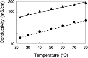
One nanofiber composite membrane with 35% PPSU reinforcement and benzyl trimethylammonium cations (2.6 mmol g−1 IEC) was selected to evaluate the effects of temperature (23–80 °C) and counter-ion (OH− or HCO3−) on conductivity. For both counter-ions, the conductivity increases with temperature up to 80 °C. With mobile OH− ions, the maximum conductivity was found to be 182 mS cm−1, which is competitive not only with the most highly conductive AEMs in the literature, but is also comparable to the proton conductivity of a Nafion11 perfluorosulfonic acid film. Membranes in the bicarbonate form exhibited a conductivity that was approximately 4-times lower than that with hydroxide counterions, which matches well with the theoretical value of 4.4 proposed by Yan and Hickner28 and the experimental results of Ren et al.34
A comparison of a nanofiber composite membrane (50 wt% PPSU and benzyl trimethylammonium fixed charge groups, with an effective membrane IEC of 2.0 mmol g−1) with other AEMs is shown in Fig. 8, where Cl− ion conductivity is plotted against the reciprocal temperature. All measurements were made at 95% relative humidity. In accordance with the recommendation of Varcoe et al.4 and for a more meaningful comparison, conductivities are presented for membranes in the chloride rather than hydroxide counterion form. The plot includes conductivities for a commercial Tokuyama A201 membrane (1.8 mmol g−1 IEC),35 a film composed of poly(ethylene-co-tetrafluoroethylene) with benzyl trimethylammonium side groups attached by radiation grafting (denoted as ETFE-g-PVBTMA in Fig. 7 with an IEC of 1.8 mmol g−1),36 a PPO based ionomer film with 1,4,5-trimethyl-2-(2,4,6-trimethoxyphenyl)imidazolium charge groups (PPO-TMIM-0.46, 1.9 mmol g−1 IEC),20 and a polystyrene/poly(vinylbenzyl trimethylammonium) di-block based membrane (PS–PVBTMA, 1.9 mmol g−1 IEC).37 In general, the chloride ion conductivity of the nanofiber composite membranes compares well to other membranes. All of the membranes exhibit an Arrhenius type temperature dependence; for the nanofiber, the activation energy was 21 kJ mol−1 (as compared to 24 kJ mol−1 for the ETFE-g-PVBTMA membrane from ref. 35, for example).
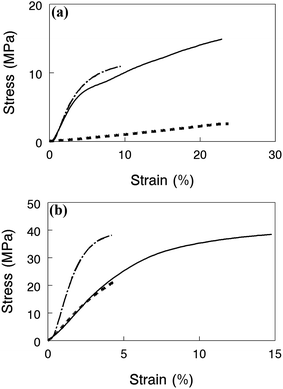
Mechanical properties of nanofiber composite membranes with benzyl trimethylammonium groups in the halide form are shown in Fig. 8 for films equilibrated in water at 23 °C (Fig. 9a) and in air at 23 °C and 20% relative humidity (Fig. 9b). Each plot shows stress–strain tensile curves for two high conductivity membranes (>60 mS cm−1 for OH−) (1) a film with 35% PPSU and 4.3 mmol g−1 IEC polyelectrolyte fibers, (2) a film with 50 wt% PPSU and 4.3 mmol g−1 IEC polyelectrolyte fibers, and (3) a third film with highly crosslinked polyelectrolyte fibers with an IEC of 2.5 mmol g−1 and 50% PPSU where conductivity (21 mS cm−1) and swelling (49%) were low. Adding more PPSU to a composite membrane at the same polyelectrolyte IEC dramatically improved its strength, as shown in Fig. 9a, where the wet stress-at-break increases from 3 MPa to 15 MPa when the PPSU content is increased from 35 wt% to 50 wt% for films with a fiber IEC of 4.3 mmol g−1. When membranes were tested dry (Fig. 9b), the composite film with 50 wt% PPSU and high IEC polyelectrolyte fibers was very strong, and reasonably ductile with a stress-at-break of 40 MPa and strain-at-break of 15%. Adding crosslinks to the polyelectrolyte fibers at a 50 wt% PPSU loading results in a membrane with a higher tensile modulus but a lower elongation at break in both the wet and dry states. This effect is attributed to the brittleness of the polyelectrolyte fibers as the crosslinking degree is increased. Again, we see that polyelectrolyte crosslinking should be minimized and the control of water swelling and mechanical properties should be achieved through the addition of PPSU.
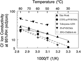 | ||
| Fig. 8 Chloride ion conductivity at 95% RH for nanofiber composite membranes and other recently published anion exchange membranes. | ||
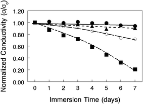
The chemical stability of nanofiber composite membranes with 50 wt% PPSU and either benzyl trimethylammonium or 1,2-dimethylimidazolium fixed charge groups was assessed by immersing films in a hot (50–80 °C) 1.0 M KOH solution for 7 days, with periodic removal and thorough washing with degassed DI water, followed by an in-plane OH− ion conductivity measurement (in degassed DI water at 23 °C). As shown in Fig. 10, the conductivity decline of the benzyl trimethylammonium film at 80 °C indicated polymer degradation over the course of the test. A separate stability experiment with a cast film of PPSU reinforcing polymer showed no weight loss after soaking in 1.0 M KOH for 7 days at 80 °C. Therefore, all of the degradation seen in Fig. 10 was associated with the polyelectrolyte nanofibers. Recent reports indicate that changing the fixed charge group chemistry38 or inserting a C6 linker between the aromatic ring of PPO and terminal fixed charge groups39,40 can improve AEM stability and should be considered in future work. At more moderate temperatures (50 °C and 60 °C), the conductivity of benzyl trimethylammonium membranes was mostly invariant for the duration of the experiment, indicating no polymer degradation. Films with 1,2-dimethylimidazolium fixed charges showed a 20% drop in conductivity even at 50 °C, which is consistent with data in a recently published study on the chemical stability of AEMs with various anion exchange groups.41 Based on this stability analysis, alkaline fuel cell tests were carried out at 60 °C with benzyl trimethylammonium nanofiber composite membranes.
Membrane electrode assembly performance
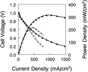
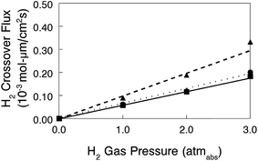
Nanofiber composite membranes with 50 wt% uncharged PPSU and benzyl trimethylammonium fixed charge groups with an effective membrane IEC of 2.0 mmol g−1 (the film with the best combination of conductivity, mechanical properties, and chemical stability) were used in alkaline fuel cell tests. Polarization and power density curves are shown in Fig. 11 for two membrane-electrode-assemblies (MEAs): (1) a thick membrane (90 μm) with Tokuyama AS-4 anode and cathode binder (1.8 mmol g−1 IEC) and (2) a thin membrane (40 μm) with uncrosslinked benzyl trimethylammonium PPO binder (2.2 mmol g−1 IEC). As expected, the latter MEA performed better, with a maximum power density of 320 mW cm−2 (HFR = 192 mΩ cm2) as compared to 213 mW cm−2 for the thicker film (HFR = 266 mΩ cm2). These preliminary fuel cell results are encouraging, and work is ongoing to fabricate a thinner membrane for reduced IR losses and also to investigate different membrane-electrode hot-pressing procedures and electrode attachment strategies (such as spraying electrode ink directly onto the membrane)8 in an effort to lower the high frequency resistance.In situ hydrogen crossover limiting current data were also collected for three MEAs with different membranes: (1) a nanofiber composite membrane with a diamine-crosslinked poly(phenylene oxide) polyelectrolyte (90 μm thick, with a hydroxide ion conductivity in room temperature water of 60 mS cm−1), and commercial Tokuyama A201 and A901 anion exchange membranes (28 and 10 μm thick, respectively, each with an OH− conductivity of 40 mS cm−1). The electrode binder for these MEAs was Tokuyama AS-4. The thickness-corrected hydrogen crossover flux (defined by eqn (4)) is plotted vs. hydrogen gas pressure in Fig. 12. While the flux for the nanofiber composite membrane is slightly higher when membrane thickness effects are considered, hydrogen crossover is still comparable with the two commercial AEMs and is strong proof that there are no defect pores and no void space between polyelectrolyte fibers and reinforcing polyphenylsulfone in a nanofiber composite film. This finding is particularly significant because the nanofiber composite membrane of Fig. 12 had been fully dried, subjected to electrode hot-pressing, and then re-hydrated before the limiting current experiment; these processing steps did not compromise/degrade the membrane structure in any way.
Conclusions
High performance nanofiber composite anion exchange membranes were made where an interconnected fiber network of diamine-crosslinked poly(phenylene oxide)-based polyelectrolyte with either benzyl trimethylammonium or 1,2-dimethylimidazolium fixed charge groups was embedded in an uncharged matrix of reinforcing polyphenylsulfone (PPSU) polymer. Membranes were prepared by: (1) electrospinning brominated poly(phenylene oxide) (BrPPO) and PPSU simultaneously to create a dual fiber mat, (2) soaking the mat in a hexamethylenediamine solution to create inter-chain crosslinks at a limited number of bromomethyl sites in the BrPPO fibers, (3) exposing the mat to chloroform, which caused PPSU to flow and fill void space around the crosslinked BrPPO fibers, and (4) soaking the mat in a solution of either trimethylamine or 1,2-dimethylimidazole solution to convert remaining bromomethyl sites to fixed charge cationic moieties. A series of membranes were fabricated with an effective membrane ion exchange capacity (IEC) of between 1.2 and 2.8 mmol g−1, where IEC was varied due to differences in: (1) the molecular weight of the fixed charge group, (2) the degree of fiber crosslinking, and (3) different amounts of PPSU in the final membrane (either 35 wt% or 50 wt%). For a membrane with 50 wt% PPSU and benzyl trimethylammonium fixed charges with an effective membrane IEC of 2.0 mmol g−1, the hydroxide ion conductivity in liquid water was high at 66 mS cm−1, with reasonable water swelling (97% at room temperature). This membrane was mechanically strong, with a stress-at-break of 15 MPa when equilibrated in water at 23 °C, and exhibited good chemical stability in a hot KOH solution. Preliminary experiments showed that nanofiber composite membranes were amenable to MEA fabrication, and such MEAs performed well in H2/O2 alkaline fuel cell tests, with a peak power of 320 mW cm−2 at 60 °C.Acknowledgements
The authors thank the Army Research Office, (Contract No. W911NF-11-1-0454) and the National Science Foundation (Grant CBET-1032948) for their financial support of this research.References
- J. R. Varcoe and R. C. T. Slade, Fuel Cells, 2005, 5, 187–200 CrossRef CAS.
- G. Merle, M. Wessling and K. Nijmeijer, J. Membr. Sci., 2011, 377, 1–35 CrossRef CAS.
- M. R. Hibbs, M. A. Hickner, T. M. Alam, S. K. McIntyre, C. H. Fujimoto and C. J. Cornelius, Chem. Mater., 2008, 20, 2566–2573 CrossRef CAS.
- J. R. Varcoe, P. Atanassov, D. R. Dekel, A. M. Herring, M. A. Hickner, P. A. Kohl, A. R. Kucernak, W. E. Mustain, K. Nijmeijer, K. Scott, T. Xu and L. Zhuang, Energy Environ. Sci., 2014, 7, 3135–3191 CAS.
- M. Faraj, E. Elia, M. Boccia, A. Filpi, A. Pucci and F. Ciardelli, J. Polym. Sci., Part A: Polym. Chem., 2011, 49, 3437–3447 CrossRef CAS.
- N. J. Robertson, H. A. Kostalik, T. J. Clark, P. F. Mutolo, H. c. D. Abruña and G. W. Coates, J. Am. Chem. Soc., 2010, 132, 3400–3404 CrossRef CAS PubMed.
- N. W. Li, L. Z. Wang and M. Hickner, Chem. Commun., 2014, 50, 4092–4095 RSC.
- G. Li, J. Pan, J. Han, C. Chen, J. Lu and L. Zhuang, J. Mater. Chem. A, 2013, 1, 12497–12502 CAS.
- M. Tanaka, K. Fukasawa, E. Nishino, S. Yamaguchi, K. Yamada, H. Tanaka, B. Bae, K. Miyatake and M. Watanabe, J. Am. Chem. Soc., 2011, 133, 10646–10654 CrossRef CAS PubMed.
- J. H. Wang, S. H. Li and S. B. Zhang, Macromolecules, 2010, 43, 3890–3896 CrossRef CAS.
- X. Ren, S. C. Price, A. C. Jackson, N. Pomerantz and F. L. Beyer, ACS Appl. Mater. Interfaces, 2014, 6, 13330–13333 CAS.
- C. G. Arges and V. Ramani, Proc. Natl. Acad. Sci. U. S. A., 2013, 110, 2490–2495 CrossRef CAS PubMed.
- C. G. Arges and V. Ramani, J. Electrochem. Soc., 2013, 160, F1006–F1021 CrossRef CAS.
- S. A. Nunez and M. A. Hickner, ACS Macro Lett., 2013, 2, 49–52 CrossRef CAS.
- M. A. Hickner, A. M. Herring and E. B. Coughlin, J. Polym. Sci., Part B: Polym. Phys., 2013, 51, 1727–1735 CrossRef CAS.
- L. Liu, Q. Li, J. Dai, H. Wang, B. Jin and R. Bai, J. Membr. Sci., 2014, 453, 52–60 CrossRef CAS.
- N. T. Rebeck, Y. F. Li and D. M. Knauss, J. Polym. Sci., Part B: Polym. Phys., 2013, 51, 1770–1778 CrossRef CAS.
- Q. Li, L. Liu, Q. Miao, B. Jin and R. Bai, Chem. Commun., 2014, 50, 2791–2793 RSC.
- X. C. Lin, J. R. Varcoe, S. D. Poynton, X. H. Liang, A. L. Ong, J. Ran, Y. Li and T. W. Xu, J. Mater. Chem. A, 2013, 1, 7262–7269 CAS.
- Y. Liu, J. Wang, Y. Yang, T. M. Brenner, S. Seifert, Y. Yan, M. W. Liberatore and A. M. Herring, J. Phys. Chem. C, 2014, 118, 15136–15145 CAS.
- C. G. Arges, L. H. Wang, J. Parrondo and V. Ramani, J. Electrochem. Soc., 2013, 160, F1258–F1274 CrossRef CAS.
- A. M. Park, F. E. Turley, R. J. Wycisk and P. N. Pintauro, Macromolecules, 2013, 47, 227–235 CrossRef.
- A. M. Park and P. N. Pintauro, Electrochem. Solid-State Lett., 2012, 15, B27–B30 CrossRef CAS.
- A. M. Park, F. E. Turley, R. J. Wycisk and P. N. Pintauro, J. Electrochem. Soc., 2015, 162, F560–F566 CrossRef CAS.
- T. Xu, Z. Liu and W. Yang, J. Membr. Sci., 2005, 249, 183–191 CrossRef CAS.
- A. M. Park and P. N. Pintauro, ECS Trans., 2011, 41, 1817–1826 CAS.
- J. B. Ballengee and P. N. Pintauro, Macromolecules, 2011, 44, 7307–7314 CrossRef CAS.
- J. L. Yan and M. A. Hickner, Macromolecules, 2010, 43, 2349–2356 CrossRef CAS.
- E. N. Komkova, D. F. Stamatialis, H. Strathmann and M. Wessling, J. Membr. Sci., 2004, 244, 25–34 CrossRef CAS.
- D. S. Kim, C. H. Fujimoto, M. R. Hibbs, A. Labouriau, Y.-K. Choe and Y. S. Kim, Macromolecules, 2013, 46, 7826–7833 CrossRef CAS.
- M. Schoemaker, U. Misz, P. Beckhaus and A. Heinzel, Fuel Cells, 2014, 14, 412–415 CrossRef CAS.
- X. Tongwen and Y. Weihua, J. Membr. Sci., 2001, 190, 159–166 CrossRef.
- S. Mafé, J. A. Manzanares and P. Ramrez, Phys. Rev. A, 1990, 42, 6245–6248 CrossRef.
- M. R. Sturgeon, C. S. Macomber, C. Engtrakul, H. Long and B. S. Pivovar, J. Electrochem. Soc., 2015, 162, F366–F372 CrossRef CAS.
- C. G. Morandi, R. Peach, H. M. Krieg and J. Kerres, J. Mater. Chem. A, 2015, 3, 1110–1120 CAS.
- T. P. Pandey, A. M. Maes, H. N. Sarode, B. D. Peters, S. Lavina, K. Vezzu, Y. Yang, S. D. Poynton, J. R. Varcoe, S. Seifert, M. W. Liberatore, V. Di Noto and A. M. Herring, Phys. Chem. Chem. Phys., 2015, 17, 4367–4378 RSC.
- M. A. Vandiver, B. R. Caire, Z. Poskin, Y. Li, S. Seifert, D. M. Knauss, A. M. Herring and M. W. Liberatore, J. Appl. Polym. Sci., 2015, 132, 41596, DOI:10.1002/app.41596.
- N. W. Li, Y. J. Leng, M. A. Hickner and C. Y. Wang, J. Am. Chem. Soc., 2013, 135, 10124–10133 CrossRef CAS PubMed.
- M. R. Hibbs, J. Polym. Sci., Part B: Polym. Phys., 2013, 51, 1736–1742 CrossRef CAS.
- H.-S. Dang, E. A. Weiber and P. Jannasch, J. Mater. Chem. A, 2015, 3, 5280–5284 CAS.
- M. G. Marino and K. D. Kreuer, ChemSusChem, 2015, 8, 513–523 CrossRef CAS PubMed.
Footnote |
| † Electronic supplementary information (ESI) available. See DOI: 10.1039/c5ta06209h |
| This journal is © The Royal Society of Chemistry 2016 |

