
 Open Access Article
 This Open Access Article is licensed under a
 Creative Commons Attribution 3.0 Unported Licence
Three dimensional architecture of carbon wrapped multilayer Na3V2O2(PO4)2F nanocubes embedded in graphene for improved sodium ion batteries†
Hongyun
Jin
ab,
Jie
Dong
a,
Evan
Uchaker
b,
Qifeng
Zhang
b,
Xuezhe
Zhou
b,
Shuen
Hou
a,
Jiangyu
Li
c and
Guozhong
Cao
*b
aFaculty of Materials Science & Chemistry, China University of Geosciences, Wuhan, 430074, China
bDepartment of Materials Science & Engineering, University of Washington, Seattle, WA 98195, USA. E-mail: gzcao@u.washington.edu; Tel: 206-616-9084; Fax: 206-543-3100
cDepartment of Mechanical Engineering, University of Washington, Seattle, WA 98195, USA
First published on 21st July 2015
Abstract
A novel Na3V2O2(PO4)2F@carbon/graphene three dimensional (3D)architecture (NVPF@C/G) is developed through a simple approach for the first time. It exhibits greatly improved rate capability and delivers a reversible capacity of 113.2 mA h g−1 at 1C.
Introduction
With major concerns regarding energy storage and conversion issues, lithium ion batteries (LIBs) have played a dominant role and occupied the majority share of the rechargeable battery sector.1–5 Wide-scale application of LIBs correlates to huge demand for lithium resources; consequently, the cost of Li compounds has tripled in the past five years alone. In the meantime, sodium ion batteries (SIBs) have emerged recently and have attracted increasing attention. Sodium holds promise for being a natural complement that can potentially even serve as a substitute for LIBs due to its high similarity in chemical properties to Li.6–9 Most importantly, elemental sodium is distributed nearly everywhere throughout the world, and its abundance, 2.64%, is nearly 440 times greater than that of Li. Moreover, sodium does not react with aluminum foil, meaning that copper can be replaced with cheaper aluminum as the current collector in SIBs.10,11 Therefore, SIBs have drawn considerable attention in recent years in view of their low cost compared to LIBs.12–16 A wide range of sodium-based compounds are being investigated as possible electrode materials for SIBs, such as Na3V2(PO4)3,17–21 Na3V2(PO4)2F3,22,23 NaMO2 (where M = V, Ni, Mn, Cr, Al, and Co),24 NaFePO4,25 Na2(Fe, Mn)PO4F,26 NaVPO4F,27 Na3V2O2x(PO4)2F3−2x,28–31 Na3V2O2(PO4)2F,32–34etc. Among these compounds, Na3V2O2(PO4)2F (NVPF) has attracted a great deal of attention because it has two high-voltage plateaus at approximately 3.65 and 4.1 V vs. Na/Na+, and a relatively large intercalation capacity (130 mA h g−1) as two Na+ can be inserted and extracted during the discharge/charge process. Rojo's group reported a mixed-valence sodium vanadium fluorophosphate SIB material with the general formula Na3V2O2x(PO4)2F3−2x synthesized by a hydrothermal method that displayed 80 mA h g−1 at 1C with no capacity fading after 30 cycles.30,31 The same group went on to synthesize Na3(VO)2(PO4)2F by ex-situ carbon coating, which delivered a capacity of 68 mA h g−1 at 1C.32 However, because the electronic conductivity of common carbon materials is not sufficiently high, the high-rate discharge capability remains unsatisfactory. Graphene, with an electron mobility value higher than 1.5 × 104 cm2 V−1 s−1at room temperature, has been utilized as LIB and SIB electrode materials.35,36 Recently, Goodenough et al. reported a Na3V2O2(PO4)2F/graphene sandwich nanostructure prepared by a solvothermal method that delivers a discharge capacity around 100.4 mA h g−1 at 1C; meanwhile, they confirmed the presence of the two voltage plateaus at 3.65 and 4.05 V by first-principles calculations.33,34For high power application, electrode materials for SIBs must possess rapid electron transport and ion diffusion capability.37,38 Carbon coating is a propitious solution to meet this requirement, and hence various kinds of carbon (graphene, matrix, carbon tube, fiber, particle, etc.) have been employed as core–shell or sandwich structures in order to improve the conductivity of the electrode materials.39–43 However, the conductivity of carbon in core–shell structures is typically not high enough, thus precipitating the need for thick shelled carbon coating, but a thicker carbon coating impedes sodium ion diffusion and worsens conductivity; the poor electronic conductivity or ionic diffusion of the electrode material would yield unsatisfying rate performance and cycle stability when used in SIBs.30,41 The sandwich structure solves the poor conductivity obstacle in the core–shell structure to some extent. Most noticeably, the conductivity of the particles wrapped by graphene located at the top and bottom of the structure is improved, but it is difficult to obtain a monolayer of particles between graphene layers, while multilayer particle structures are more commonplace. In a multilayer particle structure, the conductivity of the particles located in the middle of the layer, and thus not in contact with graphene, is extremely poor and is a crucial issue. An electrode architecture consisting of a regular 3D highly-conductive structure with nano-scale electro-active particles has been proven to provide more efficient ion and electron transport capability.43–46 Nevertheless, to the best of our knowledge, there has been no report on the 3D architecture of NVPF@C/G.
To compensate for these deficiencies, we propose the use of NVPF nanocubes embedded in graphene sheets and wrapped with carbon to fabricate a core–shell structure; thus, NVPF particles are networked by carbon and tethered to graphene to forge a large open and highly-conductive network that can facilitate both sodium ion and electron transport. In this study, for the first time, we designed a novel NVPF@C/G3D architecture by a combination of a hydrothermal method paired with carbon deposition. The resulting NVPF@C/G was evaluated as a cathode material for SIBs and presented a high reversible capacity of 137.5 mA h g−1 at 0.05C with a comparable initial coulombic efficiency of 100.9%; moreover, the material exhibited greatly improved rate capability (113.2 mA h g−1 at 1C) and 98.9% capacity retention over 40 cycles at 1C.
Experimental section
Synthesis
The synthesis process of NVPF@C/G takes place in two steps. First, the NVPF/graphene (NVPF/G) composite material was prepared by a hydrothermal method. Graphene oxide, prepared by a modified Hummers method, was immersed in 50 mL N,N-dimethyl formamide (DMF) and ultrasonically treated for 24 hours. In a typical synthesis, 2 mmol NH4H2PO4 (Sigma-Aldrich, 99.9% purity), 2 mmol NH4VO3 (Sigma-Aldrich, 99.99% purity), 1 mmol NaF (Sigma-Aldrich, 99% purity) and 1 mmol Na2CO3 (Sigma-Aldrich, 99.9% purity) were separately dissolved in 5 mL distilled water. The four precursor solutions were then added to the NVPF/G-DMF solution, and stirred for 30 minutes at 90 °C. Then, the mixture was sealed in a 100 mL capacity polytetrafluoroethylene (PTFE) lined stainless steel autoclave, which was maintained at 180 °C for 24 hours, and then naturally cooled to room temperature. A brown product was obtained after washing repeatedly with distilled water and ethanol. Secondly, 50 mg of the resulting powder was dissolved in distilled water and stirred for 30 min, and then 12 mg sucrose was added into the suspension under vigorous stirring and heating at 105 °C until dried. The powder mixture was ground and annealed at 550 °C for 1 h in a flowing argon atmosphere.Characterization
The phase of the NVPF@C/G sample was characterized by using an X-ray diffractometer (XRD, D8 Bruker X-ray diffractometer) with Cu-Kα radiation within the range of 10° to 70° (2θ), a step size of 0.02°, and an exposure time of 10 s. The accelerating voltage and current were 40 kV and 40 mA. X-ray photoelectron spectroscopy was performed using a Surface Science Instruments S-probe spectrometer (XPS, Thermo ESCALAB 250XI) with Al Kα (hv = 1486.6 eV) as the X-ray source. The X-ray spot size was 800 mm and the take-off angle was 55°, corresponding to a sampling depth of approximately 50 Å. XPS data analysis was carried out using the Service Physics ESCA 2000-A analysis program (Service Physics, Bend, OR). Microscopy investigations were performed using a JEOL JSM-7000FScanning Electron Microscope (SEM) and FEI Tecnai G20 Transmission Electron Microscope (TEM) operating at 200 kV. The compositional analysis of the as-prepared samples was performed with a thermogravimetric analysis system (TGA), an accessory of SEM.Electrochemical analysis
For electrochemical analysis, 2016 type half-cells were assembled in a glovebox (Mbraun) filled with high purity argon. The cathode slurry was prepared by dispersing the as-prepared sample, super P conductive carbon (Timcal), and PVDF binder in a NMP solvent at a respective weight ratio of 75![[thin space (1/6-em)]](https://www.rsc.org/images/entities/char_2009.gif) :20:5. The slurry was then spread onto an aluminum foil current collector and dried in a vacuum oven at 80 °C overnight. Sodium metal (Sigma Aldrich), 1 M NaClO4 in ethylene carbonate (EC)/dimethyl carbonate (DMC) (1:1 v/v), and a glass fiber were used as the counter/reference electrode, electrolyte, and separator for the Na-ion half-cells, respectively. Cyclic voltammetry (CV) was performed using an electrochemical analyzer (CH Instruments, Model 605C) in the voltage range of 4.3–2.0 V (vs. Na/Na+) at scanning rates ranging from 0.1 to 0.8 mV s−1. The current density and cycle stability performance of the sample were evaluated using the Arbin Battery Tester (BT-2000, Arbin Instruments) operating at room temperature. The half-cells were tested within the voltage range between 2.0 V and 4.3 V vs. Na/Na+ at various charging rates, and assuming a 1 C current density of 130 mA g−1; capacity values were normalized to the mass of NVPF@C/G alone.
:20:5. The slurry was then spread onto an aluminum foil current collector and dried in a vacuum oven at 80 °C overnight. Sodium metal (Sigma Aldrich), 1 M NaClO4 in ethylene carbonate (EC)/dimethyl carbonate (DMC) (1:1 v/v), and a glass fiber were used as the counter/reference electrode, electrolyte, and separator for the Na-ion half-cells, respectively. Cyclic voltammetry (CV) was performed using an electrochemical analyzer (CH Instruments, Model 605C) in the voltage range of 4.3–2.0 V (vs. Na/Na+) at scanning rates ranging from 0.1 to 0.8 mV s−1. The current density and cycle stability performance of the sample were evaluated using the Arbin Battery Tester (BT-2000, Arbin Instruments) operating at room temperature. The half-cells were tested within the voltage range between 2.0 V and 4.3 V vs. Na/Na+ at various charging rates, and assuming a 1 C current density of 130 mA g−1; capacity values were normalized to the mass of NVPF@C/G alone.
Results and discussion
The detailed assembly process and formation mechanism of the NVPF@C/G 3D architecture is illustrated in Fig. 1. Ultrasonically treated graphene oxide was combined with several precursor solutions so as to insert F−, Na+, PO43− and VO3− ions into the graphene interlayer. Then, V5+ and graphene oxide were reduced by DMF in a hydrothermal process. Along with graphene oxide reduction, NVPF was ensuingly nucleated and entrenched onto the graphene sheets. As the reaction time progressed, NVPF crystallized and grew, while the graphene layers were exfoliated to single or few layered sheets. Subsequently, NVPF crystals developed a cubic morphology, and then self-assembled into a structured multilayer of NVPF particles as shown in Fig. 1c. The as-prepared NVPF/graphene composite was immersed in a sucrose solution, then dried and annealed in argon. As a result, carbon nanoparticles homogeneously wrap the NVPF nanocubes and complete the fabrication of the core–shell while maintaining connection to graphene. Consequently, a carbon wrapped multilayer Na3V2O2(PO4)2F nanocube pillared graphene 3D architecture was obtained.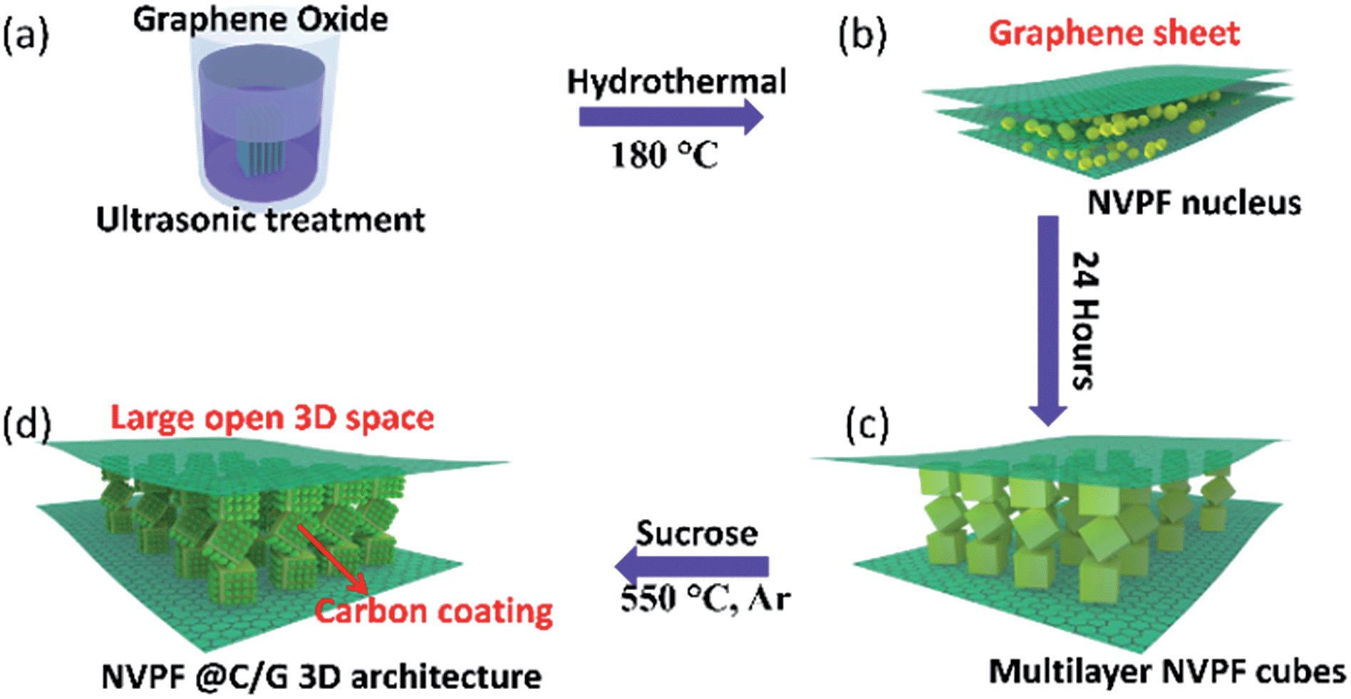 | ||
| Fig. 1 Schematic illustration of the assembly process and formation mechanism of the NVPF@C/G 3D architecture. | ||
The morphology and structural characteristics of the NVPF@C/G were examined by scanning (SEM) and transmission (TEM) electron microscopy. Fig. 2a and b reveal that the NVPF@C/G possesses a layered structure, as shown from various perspectives. Multiple layers of NVPF cubes stack between the parallel graphene sheets, which are featured by the dashed yellow lines, and the assembly of three or more layers of particles was clearly seen (Fig. 2a and b). TGA was conducted in order to analyze the region in Fig. 2b, and the carbon content in the sample was approximately 8.1 wt% (Fig. S1†). In addition, the micrographs suggest that the reduced graphene was exfoliated to sheets during the hydrothermal process, after which the NVPF nanocubes were anchored on the graphene sheets as shown in Fig. 2a and b. The high-magnification SEM micrograph clearly depicts the multilayered particle structure interlaminated between graphene layers, in which the NVPF nanocubes stack in an edge-face sharing manner (Fig. 2c). TEM images in Fig. 2e and f show that the carbon nanoparticle coating is uniformly distributed on the surface of the NVPF nanocubes, effectively forming a core–shell structure. The TEM image in Fig. 2d unveils that many NVPF nanocubes stack together between the graphene layers, corroborating the multilayer structure observed in SEM images (Fig. 2a and b). The observed lattice spacing values are 0.53 nm and 0.45 nm, corresponding to the (002) and (110) facet, respectively, which is in accordance with the XRD results (Fig. 2f, Fig. S2†). The NVPF nanocubes have an approximate edge length of 200 nm; such a small particle size signifies shorter transportation lengths for both electrons and ions, resulting in fast charge–discharge transfer kinetics. Furthermore, carbon was observed on the edge side of the NVPF nanocubes in Fig. 2e. Similar results observed from the high resolution images in Fig. 2f indicate that the cube surface was wrapped with graphene and carbon. In this instance, graphene can be described as an “express way” and the carbon as “interstates” that comprise an overall network, where electrons can travel freely in an ultrafast manner and hence improve the cycle capability and rate performance.
 | ||
| Fig. 2 SEM and TEM images of the NVPF@C/G specimen prepared by a hydrothermal method: (a–b) overall views of NVPF@C/G displaying a typical layered structure; (c) representative view of multilayered NVPF@C/G cubes between graphene layers; (d–f) TEM and HRTEM images of NVPF@C/G. | ||
The powder X-ray diffraction pattern (XRD) of NVPF@C/G is shown in Fig. 3a. All the diffraction patterns are well in agreement with the standard pattern for tetragonal Na3V2O2(PO4)2F (PDF 76-3645), space group I4/mmm[139]) with the lattice parameters a = b = 6.370 Å and c = 10.637 Å, which matches well with those in the literature.33 In this XRD pattern, there is a weak diffraction peak around 2θ ≈ 23° that corresponds to the reduced graphene phase according to the literature and compared to the Fig. S3.†47 No characteristic carbon peaks are detected, which indicates that carbon derived from sucrose may be amorphous or the amount of crystalline carbon is below the detectable limit. The layered structure of NVPF, as displayed in Fig. 3b, provides preferential pathways for the Na+ transport in this host.33,48,49 This framework structure is formed by layers of [VO5F] octahedral and [PO4] tetrahedral units. Between these layers, pairs of [VO5F] octahedra and [PO4] tetrahedral are connected by shared oxygen atoms as exhibited in the lower-left corner, while the [VO5F] octahedra are bridged by a fluorine atom between layers as shown in the lower-right corner. Between different layers, there is a broad channel for the transportation of sodium ions. This open framework structure is beneficial for sodium ion intercalation and rapid diffusion during the battery charge and discharge processes. X-Ray photoelectron spectroscopy (XPS) was then conducted to gather information on the chemical nature of the sample. The high-resolution C1s spectra show C![[double bond, length as m-dash]](https://www.rsc.org/images/entities/char_e001.gif) C (sp2) and C–C (sp2) peaks at 284.8 and 285.5 eV, respectively. Additionally, small peaks corresponding to C–O and CO separately located at 286.5 and 288.4 eV, respectively, suggest that the graphene oxide was nearly completely reduced. The high-resolution V2p3/2 and V2p1/2 XPS spectra reveal the characteristic main and satellite peaks with a binding energy of 516.4and 523.4 eV, respectively. The peak locations and the lack of shouldering verify the valence of vanadium in the sample as +4, which matches well with the literature values and is consistent with the XRD results.50,51
C (sp2) and C–C (sp2) peaks at 284.8 and 285.5 eV, respectively. Additionally, small peaks corresponding to C–O and CO separately located at 286.5 and 288.4 eV, respectively, suggest that the graphene oxide was nearly completely reduced. The high-resolution V2p3/2 and V2p1/2 XPS spectra reveal the characteristic main and satellite peaks with a binding energy of 516.4and 523.4 eV, respectively. The peak locations and the lack of shouldering verify the valence of vanadium in the sample as +4, which matches well with the literature values and is consistent with the XRD results.50,51
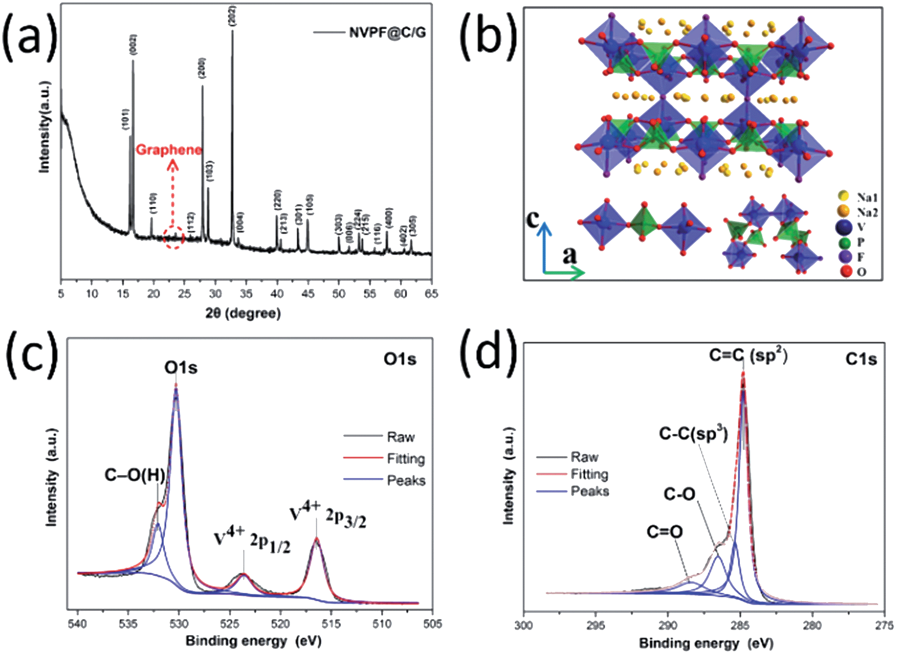 | ||
| Fig. 3 (a) XRD patterns of NVPF@C/G; (b) schematic representation of the NVPF crystal structure; (c) high-resolution O1s and V2p XPS spectra of NVPF@C/G; (d) high-resolution C1s XPS spectra of NVPF@C/G. | ||
To further evaluate the electrochemical behavior of the NVPF@C/G electrode material, cyclic voltammetry (CV) and galvanostatic charge–discharge cycling are carried out. Fig. 4a depicts the CV curves of NVPF@C/G at a scan rate of 0.5 mV s−1 over the potential range of 2–4.3 V vs. Na/Na+, in which a pair of reversible redox peaks, corresponding to the insertion and extraction of sodium ions into/out the host NVPF, were displayed. The sharp peaks and symmetrical feature of the CV curves validate the reversibility of the system. To the best of our knowledge, this is the first time the CV curves of NVPF@C/G are reported, although there are polarization phenomena.30,33 In the first cycle, two anodic peaks located at 3.75 and 4.18 V vs. Na/Na+ correspond to the release of sodium ions, the mechanism of which is described in eqn (1). Conversely, two cathodic peaks located at 3.48 and 3.88 V vs. Na+/Na are related to the insertion of sodium ions into NVPF, resulting in the formation of V4+as described in eqn (2).28
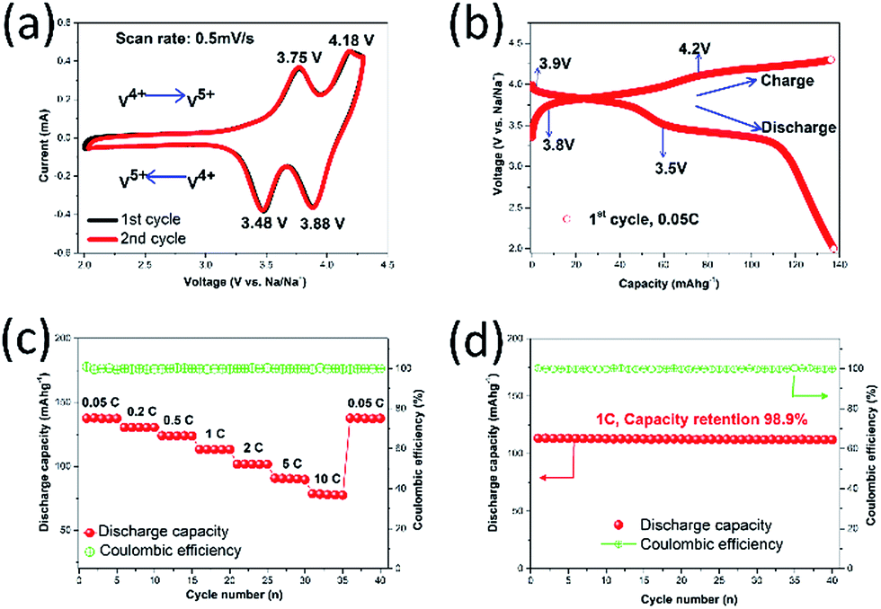 | ||
| Fig. 4 Electrochemical properties of the NVPF@C/G when tested as a SIB cathode material: (a) 1st and 2nd CV curves at a scan rate of 0.5 mV s−1; (b) initial charge–discharge voltage profiles at 0.05C; (c) rate capability; (d) cycle stability at 1C up to 40 cycles. | ||
Desodiation:
| Na3V2O2(PO4)2F ↔ NaV2O2(PO4)2F + 2Na+ + 2e− | (1) |
Sodiation:
| NaV2O2(PO4)2F + 2Na+ + 2e− ↔ Na3V2O2(PO4)2F | (2) |
Moreover, the redox peak position and shape of the 2nd CV curve exactly overlap with the first, implying excellent electrochemical reversibility. This reversibility can be attributed to NVPF nanocubes wrapped by carbon and embedded in graphene sheets, which keep the NVPF structure stable during the sodium ion intercalation/deintercalation reactions.21,52
Fig. 4b presents the initial charge and discharge curves of a NVPF@C/G half-cell at 0.05C. Two potential plateaus in the charge process were clearly observed, one plateau at approximately 3.8 V and another at 4.2 V; the discharge plateaus (around 3.9 and 3.5 V) suggest that the discharge curve corresponds well with the anodic peaks seen in the CV curves. In the initial charge/discharge cycle at 0.05C, as shown in Fig. 4b, the battery can deliver a discharge capacity of 137.5 mA h g−1 and a homologous charge capacity of 136.2 mA h g−1, in accordance with a coulombic efficiency of 100.9%, indicating excellent reversibility. Such a high first cycle efficiency is infrequent for NVPF SIB electrodes, as compared to Goodenough's and Rojo's first efficiencies of <94% and <95%, respectively, which is likely due to the partial irreversible insertion of sodium ions into the channel of the NVPF in the first discharge cycle; part of the sodium ions remain in the NVPF and fail to get out during the next charge cycle.30,33 From Fig. 4c, the specific discharge capacities tested in the voltage window of 2.0 to 4.3 V are 137.5, 130.4, 123.9, 113.2, 101.7, 90.7 and 78.5 mA h g−1 at 0.05C, 0.2C, 0.5C, 1C, 2C, 5C and 10C, respectively. With increasing charge and discharge current densities, the material only shows a moderate decrease in the capacity between discharge rates; such characteristics indicate excellent rate performance, and confirm that NVPF@C/G is suitable for sodium ion insertion/extraction at higher rates. Moreover, the present discharge capacity values are some of the best compared to previously reported results, particularly at high rate. This performance is possibly due to the large open structure and the high-conductivity network that enhances electron transport capability and hence improves sodium ion storage capacity and storage kinetics.53,54
Fig. 4d shows the cycle performance at 1C, where the initial discharge capacity is 113.4 mA h g−1 that only drops to 112.1 mA h g−1 after 40 cycles; the capacity retention is thus 98.9%. Furthermore, the coulombic efficiency is close to 100% (the minimum columbic efficiencies is 99.4%) throughout cycling, suggesting a superior electrochemical reversibility and cycle stability. This capacity retention can mainly be attributed to the carbon core–shell structure and the NVPF cubes tethered to graphene, which preserves the NVPF structure from collapsing during the sodium ion insertion and extraction processes.17,41 Many other reports have also announced that graphene addition, carbon coating and other coatings can improve the battery cyclic stability.20,39 We also compared our work with previous NVPF-based electrode materials tested for SIBs, including Na3V2O2x(PO4)2F3−2x, Na3V2O2x(PO4)2F3−2x-C composite, Na3V2O2(PO4)2F and Na3V2O2(PO4)2F/graphene, and summarized the results in Fig. 5; however, it should be noted that the electrolyte, quantity of conductive carbon or binder, and voltage window may have varied to some extent in these other studies. Unequivocally, the material synthesized in this study displayed superior electrochemical behavior. The high capacity, good rate performance, cycle stability and excellent reversibility of NVPF@C/G can be mainly ascribed to the following: (1) the nano-scale NVPF cubes shortened both the electron and ion transport distance; (2) owing to NVPF tethered to the graphene sheets, the electrolyte and sodium ion diffusion is enhanced by the relatively fixed open interspaces; (3) the high-conductivity network consisting of a graphene “express way” and carbon “interstates” efficiently accelerates electron transport, thereby enabling the electrons to travel anywhere within the NVPF nanocubes in an ultrafast manner during the redox reaction. Another possible reason leading to the performance enhancement maybe arises from the carbon core–shell and cubes tethered to graphene sheets, which can prevent the NVPF structural change to some degree during the sodium-ion insertion/desertion process. However, this needs to be confirmed in the future by a further study based on in situ HR-TEM characterization.
 | ||
| Fig. 5 Comparison of the rate performance of this work with other NVPF-based electrode materials in SIBs reported recently (the plot shows the discharge capacities according to the total mass of electrode materials; the legend contains the ratio of active materials: carbon: binder and the voltage window against Na/Na+). | ||
Conclusion
In summary, we have presented a new approach to fabricate an innovative 3D architecture-NVPF@C/G with carbon wrapped multilayer Na3V2O2(PO4)2F nanocubes embedded in a graphene structure for the first time. When the as-obtained NVPF@C/G was used as a cathode material for SIBs, it exhibited a high initial reversible capacity of 113.2 mA h g−1 at 1C, which has been the champion value to date. In addition, the capacity maintains at 112.1 mA h g−1 after 40 cycles at 1C, and the discharge capacity retention is 98.9%. Furthermore, the CV curves of NVPF@C/G were reported for the first time. The idea of using NVPF nanocubes wrapped by carbon embedded in a graphene sheet configuration may be successfully implemented for other sodium and lithium ion battery electrode materials or potentially even other layered composite materials used in advanced electro-optic fields.Acknowledgements
Part of this work was financially supported in part by the National Science Foundation (NSF, CMMI-1030048), National Nature Science Foundation of China (NSFC51102218), Natural Science Foundation of Hubei Province (No. 2013CFB412), China University of Geosciences (Wuhan) (CUG120402, CUG120118) and the University of Washington TGIF grant.Notes and references
- M. Armand and J. M. Tarascon, Nature, 2008, 451, 652–657 CrossRef CAS PubMed.
- J. Lee, A. Urban, X. Li, D. Su, G. Hautier and G. Ceder, Science, 2014, 343, 519–522 CrossRef CAS PubMed.
- Z. W. Seh, W. Li, J. J. Cha, G. Zheng, Y. Yang, M. T. McDowell, P.-C. Hsu and Y. Cui, Nat. Commun., 2013, 4, 1331 CrossRef PubMed.
- L. Shen, E. Uchaker, X. Zhang and G. Cao, Adv. Mater., 2012, 24, 6502–6506 CrossRef CAS PubMed.
- X. Li, M. Gu, S. Hu, R. Kennard, P. Yan, X. Chen, C. Wang, M. J. Sailor, J.-G. Zhang and J. Liu, Nat. Commun., 2014, 5, 4105 CAS.
- C. Cao, W. Liu, L. Tan, X. Liao and L. Li, Chem. Commun., 2013, 49, 11740–11742 RSC.
- S. W. Kim, D. H. Seo, X. Ma, G. Ceder and K. Kang, Adv. Energy Mater., 2012, 2, 710–721 CrossRef CAS PubMed.
- W. Luo, M. Allen, V. Raju and X. Ji, Adv. Energy Mater., 2014, 1400554 Search PubMed.
- N. Yabuuchi, M. Kajiyama, J. Iwatate, H. Nishikawa, S. Hitomi, R. Okuyama, R. Usui, Y. Yamada and S. Komaba, Nat. Mater., 2012, 11, 512–517 CrossRef CAS PubMed.
- M. Mikkor, J. Electrochem. Soc., 1985, 132, 991–998 CrossRef CAS PubMed.
- E. Uchaker, Y.-Z. Zheng, S. Li, S. L. Candelaria, S. Hu and G. Cao, J. Mater. Chem. A, 2014, 2, 18208–18214 CAS.
- X. Han, Y. Liu, Z. Jia, Y.-C. Chen, J. Wan, N. Weadock, K. J. Gaskell, T. Li and L. Hu, Nano Lett., 2013, 14, 139–147 CrossRef PubMed.
- M. D. Slater, D. Kim, E. Lee and C. S. Johnson, Adv. Funct. Mater., 2013, 23, 947–958 CrossRef CAS PubMed.
- L. Wang, Y. Lu, J. Liu, M. Xu, J. Cheng, D. Zhang and J. B. Goodenough, Angew. Chem., Int. Ed., 2013, 52, 1964–1967 CrossRef CAS PubMed.
- Y. You, X.-L. Wu, Y.-X. Yin and Y.-G. Guo, Energy Environ. Sci., 2014, 7, 1643–1647 CAS.
- Y. Shao, J. Xiao, W. Wang, M. Engelhard, X. Chen, Z. Nie, M. Gu, L. V. Saraf, G. Exarhos and J.-G. Zhang, Nano Lett., 2013, 13, 3909–3914 CrossRef CAS PubMed.
- W. Duan, Z. Zhu, H. Li, Z. Hu, K. Zhang, F. Cheng and J. Chen, J. Mater. Chem. A, 2014, 2, 8668–8675 CAS.
- Z. Jian, W. Han, X. Lu, H. Yang, Y.-S. Hu, J. Zhou, Z. Zhou, J. Li, W. Chen, D. Chen and L. Chen, Adv. Energy Mater., 2013, 3, 156–160 CrossRef CAS PubMed.
- Y. H. Jung, C. H. Lim and D. K. Kim, J. Mater. Chem. A, 2013, 1, 11350–11354 CAS.
- S. Li, Y. F. Dong, L. Xu, X. Xu, L. He and L. Q. Mai, Adv. Mater., 2014, 26, 3545–3553 CrossRef CAS PubMed.
- K. Saravanan, C. W. Mason, A. Rudola, K. H. Wong and P. Balaya, Adv. Energy Mater., 2013, 3, 444–450 CrossRef CAS PubMed.
- W. Song, Z. Wu, J. Chen, Y. Zhu, H. Hou, Q. Lan and X. Ji, Langmuir, 2014, 30, 12438–12446 CrossRef CAS PubMed.
- Y. Wang, M. Klenk, K. Page and W. Lai, Chem. Mater., 2014, 26, 5613–5624 CrossRef CAS.
- K. Chihara, A. Kitajou, I. D. Gocheva, S. Okada and J.-i. Yamaki, J. Power Sources, 2013, 227, 80–85 CrossRef CAS PubMed.
- V. Palomares, P. Serras, I. Villaluenga, K. B. Hueso, J. Carretero-Gonzalez and T. Rojo, Energy Environ. Sci., 2012, 5, 5884–5901 CAS.
- R. Tripathi, S. M. Wood, M. S. Islam and L. F. Nazar, Energy Environ. Sci., 2013, 6, 2257–2264 CAS.
- J. Song, M. Xu, L. Wang and J. B. Goodenough, Chem. Commun., 2013, 49, 5280–5285 RSC.
- K. B. Hueso, M. Armand and T. Rojo, Energy Environ. Sci., 2013, 6, 734–749 CAS.
- P. Serras, V. Palomares, J. Alonso, N. Sharma, J. Miguel Lopez del Amo, P. Kubiak, M. Luisa Fdez-Gubieda and T. Rojo, Chem. Mater., 2013, 25, 4917–4925 CrossRef CAS.
- P. Serras, V. Palomares, A. Goñi, I. G. de Muro, P. Kubiak, L. Lezama and T. Rojo, J. Mater. Chem., 2012, 22, 22301–22308 RSC.
- P. Serras, V. Palomares, A. Goni, P. Kubiak and T. Rojo, J. Power Sources, 2013, 241, 56–60 CrossRef CAS PubMed.
- P. Serras, V. Palomares, P. Kubiak, L. Lezama and T. Rojo, Electrochem. Commun., 2013, 34, 344–347 CrossRef CAS PubMed.
- M. Xu, L. Wang, X. Zhao, J. Song, H. Xie, Y. Lu and J. B. Goodenough, Phys. Chem. Chem. Phys., 2013, 15, 13032–13037 RSC.
- M. Xu, P. Xiao, S. Stauffer, J. Song, G. Henkelman and J. B. Goodenough, Chem. Mater., 2014, 26, 3089–3097 CrossRef CAS.
- L. Shen, B. Ding, P. Nie, G. Cao and X. Zhang, Adv. Energy Mater., 2013, 3, 1484–1489 CrossRef CAS PubMed.
- C. Zhu, K. Song, P. A. van Aken, J. Maier and Y. Yu, Nano Lett., 2014, 14, 2175–2180 CrossRef CAS PubMed.
- J. Xie, X. Yang, S. Zhou and D. Wang, ACS Nano, 2011, 5, 9225–9231 CrossRef CAS PubMed.
- S. Zhou, X. Yang, Y. Lin, J. Xie and D. Wang, ACS Nano, 2011, 6, 919–924 CrossRef PubMed.
- L.-H. Hu, F.-Y. Wu, C.-T. Lin, A. N. Khlobystov and L.-J. Li, Nat. Commun., 2013, 4, 1687 CrossRef PubMed.
- Y. Kim, Y. Park, A. Choi, N.-S. Choi, J. Kim, J. Lee, J. H. Ryu, S. M. Oh and K. T. Lee, Adv. Mater., 2013, 25, 3045–3049 CrossRef CAS PubMed.
- D. Su, H.-J. Ahn and G. Wang, Chem. Commun., 2013, 49, 3131–3133 RSC.
- Y. Wen, K. He, Y. Zhu, F. Han, Y. Xu, I. Matsuda, Y. Ishii, J. Cumings and C. Wang, Nat. Commun., 2014, 5, 4033 CAS.
- Y. Yan, Y.-X. Yin, Y.-G. Guo and L.-J. Wan, Adv. Energy Mater., 2014, 4, 1301584 Search PubMed.
- T. S. Arthur, D. J. Bates, N. Cirigliano, D. C. Johnson, P. Malati, J. M. Mosby, E. Perre, M. T. Rawls, A. L. Prieto and B. Dunn, MRS Bull., 2011, 36, 523–531 CrossRef CAS.
- N. Cirigliano, G. Sun, D. Membreno, P. Malati, C. Kim and B. Dunn, Energy Technol., 2014, 2, 362–369 CrossRef CAS PubMed.
- J. W. Long, B. Dunn, D. R. Rolison and H. S. White, Chem. Rev., 2004, 104, 4463–4492 CrossRef CAS.
- H. J. Shin, K. K. Kim, A. Benayad, S. M. Yoon, H. K. Park, I. S. Jung, M. H. Jin, H. K. Jeong, J. M. Kim and J. Y. Choi, Adv. Funct. Mater., 2009, 19, 1987–1992 CrossRef CAS PubMed.
- W. Massa, O. V. Yakubovich and O. V. Dimitrova, Solid State Sci., 2002, 4, 495–501 CrossRef CAS.
- H. Pan, Y.-S. Hu and L. Chen, Energy Environ. Sci., 2013, 6, 2338–2360 CAS.
- F. Gracia, F. Yubero, J. Espinós and A. González-Elipe, Appl. Surf. Sci., 2005, 252, 189–195 CrossRef CAS PubMed.
- E. Hryha, E. Rutqvist and L. Nyborg, Surf. Interface Anal., 2012, 44, 1022–1025 CrossRef CAS PubMed.
- L. Shen, H. Li, E. Uchaker, X. Zhang and G. Cao, Nano Lett., 2012, 12, 5673–5678 CrossRef CAS PubMed.
- X.-C. Chen, W. Wei, W. Lv, F.-Y. Su, Y.-B. He, B. Li, F. Kang and Q.-H. Yang, Chem. Commun., 2012, 48, 5904–5906 RSC.
- F. Y. Su, Y. B. He, B. H. Li, X. C. Chen, C. H. You, W. Wei, W. Lv, Q. H. Yang and F. Y. Kang, Nano Energy, 2012, 1, 429–439 CrossRef CAS PubMed.
Footnote |
| † Electronic supplementary information (ESI) available. See DOI: 10.1039/c5ta03164h |
| This journal is © The Royal Society of Chemistry 2015 |