 Open Access Article
Rational design of mesoporous NiFe-alloy-based hybrids for oxygen conversion electrocatalysis†
Suqin
Ci‡
,
Shun
Mao‡
,
Yang
Hou
,
Shumao
Cui
,
Haejune
Kim
,
Ren
Ren
,
Zhenhai
Wen
* and
Junhong
Chen
*
Department of Mechanical Engineering, University of Wisconsin-Milwaukee, 3200 North Cramer Street, Milwaukee, Wisconsin 53211, United States. E-mail: wenzhenhai@yahoo.com; jhchen@uwm.edu
First published on 20th February 2015
Abstract
A mesoporous NiFe-based alloy was synthesized through a hard-template technique and investigated as the electrocatalyst for oxygen evolution reaction (OER) and oxygen reduction reaction (ORR). Precious metal-free elements, i.e., nitrogen (N), nickel (Ni), and iron (Fe), were merged together through either doping or alloying to form a mesoporous structure supporting NiFe-alloy electrocatalyst (m-NiFe/CNx). The synergetic effects from multiple active sites, in combination with structural merits, endowed the m-NiFe/CNx electrocatalyst with an excellent electrocatalytic activity for both OER and ORR, including high activity, fast kinetics, modest overpotential, and excellent stability. The m-NiFe/CNx also featured a simple and scalable synthesis process with a low cost, which makes it an attractive alternative catalyst to precious metal-based electrocatalysts for OER and ORR.
Introduction
The generation of hydrogen-based renewable energy sources has become increasingly important in the search for viable alternatives to fossil fuel-based technologies in the world's renewable energy mix.1–7 The implementation of numerous sustainable energy sources is highly dependent upon oxygen electrochemistry, i.e., the oxygen evolution reaction (OER) and the oxygen reduction reaction (ORR), which are of critical importance for the mutual conversion between electrical energy and chemical energy in electrolysis cells, metal air batteries, and fuel cells.8–10 OER plays a pivotal role in water splitting and solar fuel synthesis,11–17 whereas ORR is a well-known critical process for cathodes of various fuel cells and metal–air batteries.18–26 Unfortunately, both OER and ORR proceed via multi-electron transfer with sluggish kinetics that governs the overall reaction rate.12,27–30 Moreover, Ir- and Pt-based materials, which are probably the best electrocatalysts for OER and ORR, are rare and precious substances and suffer from the drawbacks of high cost and declining activity over long-term operation, limiting their practical applications.31–36 To date, the development of bifunctional nanocatalysts for OER and ORR is still in its infancy,37–44 and there is abundant room for the exploration of novel electrocatalysts.45,46We herein report an alloy-based electrocatalyst for OER and ORR through a rational and elaborate design, featuring the advantages of easy preparation, low cost, enhanced reaction rate, reduced overpotential, good durability, and enhanced energy conversion efficiency. In the present strategy, mesoporous SBA-15 was selected as the catalyst support, which was decorated by nitrogen-doped (N-doped) nanocarbon that acted as the nanoreactor for the in situ growth of well-dispersed alloy nanocatalysts. Precious metal-free elements, i.e., nitrogen (N), nickel (Ni), and iron (Fe), were incorporated into the mesoporous structure through doping or alloying, which allowed the multiple electrocatalytic sites to synergistically contribute to both OER and ORR. In this way, the as-designed catalyst offers a smooth route for electron transfer benefitting from the improved electrical conductivity, thus leading to a high mass (ions and electrolytes) transport efficiency thanks to its mesoporous structure. Moreover, the large surface area and highly dispersed catalytic sites enable the electrocatalysts to significantly boost OER and ORR performance, which compares favorably with both Ir/C catalysts for OER and Pt/C catalysts for ORR and show much better stability than precious metal catalysts.
Experimental section
Material and method
Commercial 10% Pt and 10% Ir on Vulcan XC-72 was purchased from the Fuel Cell Store (www.fuelcellstore.com). All the reagents were of analytical grade and purchased from Sigma Aldrich without further treatment. SBA-15 was synthesized according to a method mentioned in previous reports.47 In a typical synthesis of m-NiFe/CNx, 2.0 g SBA-15, 2.02 g FeCl3·6H2O ((7.5 mM)), 1.775 g NiCl2·6H2O (7.5 mM), and 8 g cyanamide were added in 20 mL water and stirred until it was completely dry to form a tawny powder. The mixtures were heated to 750 °C at a rate of 1 °C min−1 and maintained at that temperature for 1 hour under an Ar atmosphere. The reference samples, i.e. NiFe/CNx, m-Ni/CNx, and m-Fe/CNx, were prepared through a similar method to m-NiFe/CNx, but without adding SBA-15, or FeCl3·6H2O, or NiCl2·6H2O, respectively.Characterization
The morphology and nanostructures of the samples were obtained using a Hitachi (H 9000 NAR) transmission electron microscope (TEM) and a Hitachi (S-4800) scanning electron microscope (SEM) equipped with an energy-dispersive spectroscopy analyzer. The X-ray powder diffraction (XRD) patterns were tested in a Scintag XDS 2000 X-ray powder diffractometer with monochromatized CuKα radiation (λ = 1.5418 Å). X-ray photoelectron spectroscopy (XPS) was conducted using an HP 5950A ESCA spectrometer with Mg Kα as the source and the C 1s peak at 284.6 eV as an internal standard. Specific surface areas were measured by Brunauer–Emmett–Teller (BET) nitrogen adsorption–desorption using a Quantachrome Autosorb gas-sorption system.Electrochemical measurement
The catalyst suspension was prepared as follows: 3.0 mg electrode material (m-NiFe/CNx, NiFe/CNx, m-Ni/CNx, m-Fe/CNx, Ir/C or Pt/C) was dispersed in a mixture of 0.05 mL Nafion and 0.45 mL distilled water through ultrasonic agitation for 5 minutes. The working electrode, i.e., glassy carbon electrode (GCE, φ: 3.0 mm) and rotating disk electrode (RDE), were first polished using aluminum oxide (Al2O3, 1 μm and 0.3 μm) powder followed by rinsing thoroughly with distilled water. After successive sonication in deionized water and ethanol, the electrode was rinsed with double distilled water and dried at room temperature. The working electrode was prepared by dropping 6 μL of catalyst ink on the glassy carbon electrode and drying it at room temperature.OER test
The electrocatalytic activity for OER was measured with a three-electrode system using a bipotentiostat (CHI760D, CHI Instrument), in which a platinum wire and a saturated Ag/AgCl electrode were used as the counter electrode and the reference electrode, respectively. RRDE measurements were conducted in an argon-saturated KOH solution (0.1 M) at a scan rate of 5 mV s−1 and a rotation speed of 1600 rpm (RDE-3A Rotating Ring Disk Electrode Apparatus Ver.1.2, ALS Co., Ltd). The Pt ring was treated by cycling between 0 and 1.2 V in 0.5 M H2SO4 for 10 cycles before performing RRDE experiments. The potential on the Pt ring electrode was set to 0.6 V and 1.5 V for monitoring the products produced at the disk electrode.ORR test
Electrochemical measurements for ORR were also performed on the same electrochemical instrument using a three-electrode system, in which the modified electrode was used as the working electrode, a platinum wire was used as the counter electrode, and a saturated Ag/AgCl electrode was used as the reference electrode. The supporting electrolyte was a 0.1 M KOH solution. Cyclic voltammetry (CV) was carried out at a scan rate of 50 mV s−1. The polarization curves for ORR were obtained through RDE and RRDE techniques at a scan rate of 5 mV s−1, and the current was normalized to surface the area of the electrode. Linear sweep voltammetry (LSV) was performed at a scan rate of 5 mV s−1 with varying rotating speed from 400 rpm to 2500 rpm for the ORR measurements. Experiments for OER were conducted by rotating the working electrode continuously at 1600 rpm.Rotating ring-disk electrode (RRDE) measurements
The disk electrode was scanned at a rate of 5 mV s−1, and the ring potential was constantly set at 1.5 V vs. RHE. The electron transfer number (n) and the hydrogen peroxide yield (% H2O2) were determined by the following two equations:| n = 4Id/(Id + Ir/N) |
| % H2O2 = 200Ir/(NId + Ir) |
Electrochemical impedance spectroscopy (EIS) measurements
EIS tests were conducted at 1.5 V vs. RHE in a frequency range of 100 kHz to 50 mHz. The data were plotted in a Nyquist curve; charge transfer resistance (Rct) was determined by fitting the measured impedance data to an equivalent circuit.RHE calibration
An Ag/AgCl electrode (saturated KCl) was used as the reference electrode in all the measurements. The measured potentials were converted to the reversible hydrogen electrode (RHE) via the Nernst equation:| ERHE = EAg/AgCl + 0.059pH + E0Ag/AgCl |
Results and discussion
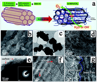
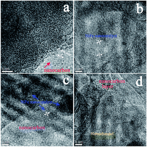
An electrocatalyst, i.e., a nitrogen-doped nanocarbon modified SBA-15 supported NiFe-alloy (m-NiFe/CNx), was synthesized by a simple method (Fig. 1a). The process started with thoroughly mixing cyanamide, SBA-15, FeCl3, and NiCl2 in an aqueous solution followed by stirring them until the mixture completely dried. The dried powder was then heated to 750 °C under an argon environment. The cyanamide was initially polymerized to form carbon nitride polymer in the nanochannels of SBA-15 and then slowly decomposed to generate carbon- and nitrogen-containing gases (e.g., C2N2+ and C3N2+),48–51 which reacted with Ni and Fe sources to produce Ni, Fe, and NiFe-alloy nanoparticles in the mesopores. These Ni or Fe nanoparticles then functioned as catalysts for the in situ growth of N-doped nanocarbon decorated SBA-15.Scanning electron microscopy (SEM) was carried out to study the morphology of the as-synthesized catalyst. The SEM image of the m-NiFe/CNx shows a well-defined shape and morphology decorated with plenty of carbon nanostructures (Fig. 1b); in contrast, the pristine SBA-15 shows a blurry and distorted SEM image due to poor electrical conductivity (Fig. S1†), suggesting the electrical conductivity was significantly improved in the m-NiFe/CNx compared with SBA-15. Fig. 1c shows the transmission electron microscopy (TEM) image of the m-NiFe/CNx, also confirming that carbon nanofibers stick out from the samples (Fig. 1c). The magnified TEM images indicate that lots of nanoparticles are dispersed in the porous channels of the m-NiFe/CNx samples (Fig. 1d), and a film of carbon modifies the m-NiFe/CNx samples (Fig. 1e–g). According to high-resolution TEM (HRTEM) images from different regions (Fig. 2), the m-NiFe/CNx maintains an ordered porous structure of SBA-15 with a channel size of around 6.0 nm; these channels can provide enough space for electrolyte or ion transport. In addition, there are many nanoparticles dispersed in the porous channels. Further analyses indicate that the nanoparticles have a lattice spacing of around 0.21 nm (Fig. 1g and 2c and d), corresponding with the (111) crystalline planes of the NiFe alloy, suggesting that these nanoparticles are NiFe alloy nanoparticles. In addition, the well-defined graphite crystal structure with an interlayer d-spacing of ∼0.34 nm was either sparsely dispersed through or compactly decorated around SBA-15.
According to the powder X-ray diffraction (XRD) patterns (Fig. 3a), two peaks assigned to (002) and (101) planes of graphite carbon can be observed at about 26.1° and 44.3°, two strong peaks at 43.5° and 50.8° indicate that the dominant products are NiFe alloy (JCPDS no. 23-0297), and the left side peaks can be assigned to the characteristic peaks of iron carbide. Based on nitrogen adsorption–desorption measurements, it can be inferred that the m-NiFe/CNx has a Brunauer–Emmett–Teller (BET) surface area of 246.9 m2 g−1, a pore volume of 0.39 cm3 g−1, and an average pore size of ∼6.1 nm (Fig. 3b); this value is larger than that of NiFe/CNx. The energy-dispersive X-ray spectroscopy (EDS) map further verified the distributions and intensities of Ni, Fe, N, C, Si, and O elements that match well with the SEM image of the m-NiFe/CNx (Fig. 4). A series of peaks corresponding to C, N, Fe, Ni, and O are found in the survey X-ray photoelectron spectrum (XPS), reconfirming the existence of these elements in m-NiFe/CNx (Fig. 5a). The high resolution peak of N 1s (Fig. 5c) can be fitted to pyridine-type nitrogen (398.2 eV), pyrrolic-type N doping (399.9 eV), graphite-type nitrogen (401.2 eV), and pyridine N-oxide (402.1 eV). In addition, two principal peaks in the Ni 2p3/2 spectrum centered at 854.3 and 855.6 eV could be attributed to the alloy-state and oxide-state of Ni (Fig. 5d), while the Fe 2p3/2 signals at about 706.5 and 710.3 eV can be assigned to alloy Fe and Fe–O bonds (Fig. 5e), respectively. It should be noted that the samples produced without adding SBA-15, i.e., NiFe/CNx, are NiFe-carbon core–shell microspheres with a size of around 1.0 μm (Fig. 6), suggesting that the pores of SBA-15 served as nanoreactors for the formation of nanocatalysts.
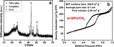 | ||
| Fig. 3 (a) XRD pattern and (b) N2 adsorption–desorption isothermal curve of the as-prepared m-NiFe/CNx. | ||
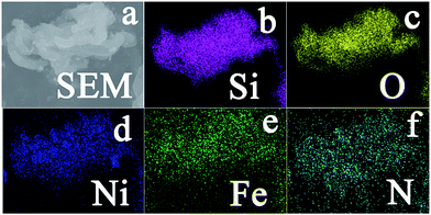 | ||
| Fig. 4 (a) SEM image of the as-prepared m-NiFe/CNx; and X-ray elemental mapping of (b) Si, (c) O, (d) Ni, (e) Fe, and (N) for the m-NiFe/CNx. | ||
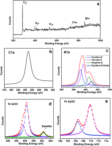 | ||
| Fig. 5 (a) Survey XPS spectrum of the m-NiFe/CNx, (b) high resolution XPS spectra of the C 1s, (c) N 1s, (d) Ni 2p3/2, and (e) Fe 2p3/2 in m-NiFe/CNx after Shirley background removal. | ||
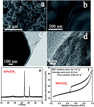 | ||
| Fig. 6 (a and b) SEM images, (c and d) TEM images, (e) XRD pattern, and (f) N2 adsorption–desorption isothermal curve of the NiFe/CNx. | ||
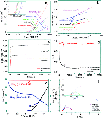
The electrochemical catalytic properties of OER were measured by linear scan voltammogram (LSV) for a set of materials, including m-NiFe/CNx, NiFe/CNx, m-Ni/CNx (Fig. S2a and b†), m-Fe/CNx (Fig. S2c and d†), and commercial Ir/C, which were either purchased or prepared by our group. As shown in Fig. 7a, the anodic current recorded with the m-NiFe/CNx showed an onset OER potential at ∼1.45 V (vs. RHE) with an overpotential (η) of 0.22 V. The onset potential was significantly lower than those of the m-Ni/CNx, m-Fe/CNx, and NiFe/CNx samples, whose corresponding onset potentials (overpotentials) were found to be ∼1.56 (η = 0.33 V), 1.67 V (η = 0.44 V), and ∼1.52 (η = 0.29 V), respectively. Notably, the overpotential of the m-NiFe/CNx electrode was even smaller than that of the Ir/C catalyst, which showed an onset potential at ∼1.50 V (η = 0.27 V). The m-NiFe/CNx also showed better electrocatalytic performance than the porous Fe2O3 (Fig. S3a and b†), porous NiO (Fig. S3c and d†), and C3N4 samples, as shown by a remarkably higher current density, a significantly lower overpotential and a smaller Tafel slope (Fig. S4†).
The catalytic activities for OER were further evaluated by the overpotential required to achieve an OER current density of 10 mA cm−2, a commonly-used criterion for evaluating OER catalysts.13,37 The m-NiFe/CNx obtained a current density of 10 mA cm−2 at 1.59 V (Fig. 7a). In contrast, the m-Ni/CNx, m-Fe/CNx, porous NiO, and NiFe/CNx samples showed a current density of 10 mA cm−2 until the potential reached ∼1.70, ∼1.88, ∼2.0, and ∼1.75 V, respectively. The porous Fe3O4 and the g-C3N4 showed negligible OER activities over the potential range investigated. As expected, the m-NiFe/CNx also showed a higher catalytic activity than the Ir/C catalysts, which generated a current density of 10 mA cm−2 at 1.65 V. Tafel curves were plotted from the corresponding OER polarization curves, as shown in Fig. 7b. The m-NiFe/CNx showed a Tafel slope of 59.1 mV dec−1; this value is slightly smaller than that of the Ir/C (61.5 mV dec−1) and is considerably smaller than those of m-Ni/CNx (94.5 mV dec−1), m-Fe/CNx (102.8 mV dec−1), NiFe/CNx (73.6 mV dec−1), NiO (97.5 mV dec−1), Fe3O4 (104.5 mV dec−1), and C3N4 (130.6 mV dec−1). The lower overpotential, higher current density, and smaller Tafel slope of the m-NiFe/CNx indicate significantly improved catalytic activity and enhanced kinetics for OER.
The m-NiFe/CNx catalyst also shows higher activity and better durability upon long-term OER operation compared with the Ir/C electrocatalyst. As shown in Fig. 7c, when galvanostatically biased at 10 mA cm−2, the m-NiFe/CNx hybrid maintained a constant operating potential at ∼1.61 V after running for 1000 seconds, whereas the Ir/C catalyst showed an observable increase in overpotential by ∼20 mV. When operated galvanostatically at a current density of 5 mA cm−2, the working potential remained at ∼1.53 V for the m-NiFe/CNx, which also showed a smaller overpotential than the Ir/C catalyst. The durability of the m-NiFe/CNx hybrid and the Ir/C catalyst were also assessed through chronoamperometric measurements at 1.6 V vs. RHE (Fig. 7d). The current density of m-NiFe/CNx was nearly twice that of Ir/C, further confirming a higher OER catalytic activity of the m-NiFe/CNx than that of the commercial Ir/C. Moreover, the current of the m-NiFe/CNx was maintained more than 90% of the initial current during the 20![[thin space (1/6-em)]](https://www.rsc.org/images/entities/char_2009.gif) 000 s test whereas the Ir/C lost nearly 50% of its initial current density. Rotating ring-disk electrode (RRDE) voltammograms were further conducted by applying a given voltage at the platinum ring electrode upon scanning from 1.0 to 1.9 V (vs. RHE) at the disk electrode. In this way, we were able to monitor the intermediate products produced in the disk electrode during the scanning. In particular, the ring potential was set as 0.6 V to detect the O2 reduction and 1.5 V to measure H2O2 oxidation. As shown in Fig. 7e, almost no oxidation current was observed on the ring electrode when it was set at 1.5 V during the scanning, suggesting that there was negligible H2O2 formed in this process. In contrast, an apparent reduction current was observed starting at around 1.5 V due to the evolution of oxygen when 0.6 V was applied at the ring electrode. These results demonstrated that the m-NiFe/CNx catalyzed water oxidation through a four-electron route with the evolution of O2. Furthermore, electrical impedance spectroscopy (EIS) tests demonstrated that the m-NiFe/CNx hybrid had the lowest charge transfer resistance among these electrocatalysts when it catalyzed the OER (Fig. 7f).
000 s test whereas the Ir/C lost nearly 50% of its initial current density. Rotating ring-disk electrode (RRDE) voltammograms were further conducted by applying a given voltage at the platinum ring electrode upon scanning from 1.0 to 1.9 V (vs. RHE) at the disk electrode. In this way, we were able to monitor the intermediate products produced in the disk electrode during the scanning. In particular, the ring potential was set as 0.6 V to detect the O2 reduction and 1.5 V to measure H2O2 oxidation. As shown in Fig. 7e, almost no oxidation current was observed on the ring electrode when it was set at 1.5 V during the scanning, suggesting that there was negligible H2O2 formed in this process. In contrast, an apparent reduction current was observed starting at around 1.5 V due to the evolution of oxygen when 0.6 V was applied at the ring electrode. These results demonstrated that the m-NiFe/CNx catalyzed water oxidation through a four-electron route with the evolution of O2. Furthermore, electrical impedance spectroscopy (EIS) tests demonstrated that the m-NiFe/CNx hybrid had the lowest charge transfer resistance among these electrocatalysts when it catalyzed the OER (Fig. 7f).
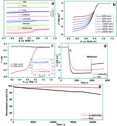
The m-NiFe/CNx also shows an outstanding electrocatalytic activity for ORR. Fig. 8a shows cyclic voltammograms (CV) obtained from different electrodes. The porous NiO, porous Fe2O3, C3N4, and m-Ni/CNx samples showed an onset potential below 0.7 V (vs. RHE) and displayed a quite low current density (<2 mA cm−2), while the m-Fe/CNx and NiFe/CNx exhibited a distinct positive shift to ∼0.88 V and ∼0.86 V (vs. RHE) in onset potential and an improved limiting current density of ∼3.2 mA cm−2 and ∼4.3 mA cm−2, respectively. Notably, the m-NiFe/CNx manifested an onset potential of 0.91 V (vs. RHE) and a limiting current density of 6.3 mA cm−2. The more positive onset potential, which is associated with a higher limiting current density, provides solid evidence that the m-NiFe/CNx possessed a higher catalytic activity than its counterparts (Fig. S5†).
To better understand the catalytic properties of the catalysts for ORR, the rotating-disk linear sweep voltammograms were conducted by scanning the potential from 1.2 to 0.3 V at different rotation rates (Fig. 8b and S6†). The three samples, i.e., m-Ni/CNx, m-Fe/CNx, and C3N4, showed an increasing limiting current density rather than a steady-state limiting current density, suggesting that the ORR went through a multi-step process with H2O2 intermediates in these electrodes. In contrast, the m-NiFe/CNx exhibited a stable limiting current density, indicating that the ORR predominantly proceeded through a one-step reaction pathway to produce water for the m-NiFe/CNx electrode. It should be noted that the NiFe/CNx can also obtain a stable limiting current density; however, the limiting current density at the m-NiFe/CNx electrode is 1.5 times higher than that of NiFe/CNx.
To verify the ORR catalytic pathways of the m-NiFe/CNx, we performed RRDE measurements to monitor the formation of peroxide species (HO2−) and to estimate the number of electrons transferred during the ORR process. Fig. 8c shows the ring current density (Ir) and disk current density (Id) upon cathodic scanning. A very small Ir was detected with the potential scanning to the ORR region (0.20–0.80 V), suggesting only a small amount of H2O2 was produced. Actually, the yield of HO2− at the m-NiFe/CNx electrode was evaluated to be below 16.5% over the potential range of 0.20–0.80 V, and the electron transfer number was calculated based on Ir and Id to be 3.6–3.8 (inset of Fig. 8c).
We also compared the m-NiFe/CNx catalyst with a commercial Pt/C catalyst for their ORR electrocatalytic performance. Although the m-NiFe/CNx showed a slightly higher onset potential than the Pt/C-modified electrode (Fig. S7†), the former manifests at least three distinct advantages over the Pt/C catalyst. First, with the addition of 10 vol% methanol to the electrolyte, the m-NiFe/CNx displayed a negligible current response, while the Pt/C almost decreased by half in current density (Fig. 8d), suggesting that the m-NiFe/CNx shows very good tolerance to the fuel for directed methanol fuel cells, i.e., methanol. Second, the m-NiFe/CNx had greater durability than the Pt/C. The chronoamperometric measurements at 0.65 V were performed for more than 6 h to assess their durability (Fig. 8e), which led to less than a 10% loss of initial current density for the m-NiFe/CNx, but more than a 25% loss for the Pt/C. Third, the m-NiFe/CNx also cost less than one-tenth of the commercial Pt/C catalysts based on a rough estimate from our experiments.
The abovementioned results clearly demonstrate that the m-NiFe/CNx has a higher activity than Ir/C for OER and possesses attractive advantages over Pt/C for ORR. Activities for OER and ORR were judged by the difference between the potential required to oxidize water at a current density of 10 mA cm−2 and for oxygen reduction at a current density of 3 mA cm−2. The smaller difference indicates a better performance for a reversible oxygen electrode. By this metric, the m-NiFe/CNx has an oxygen electrode activity of 0.83 V (Fig. 9). The as-developed m-NiFe/CNx shows an electrocatalytic activity comparable to that of the Pt/C for catalyzing ORR and that of the Ir/C catalyst for catalyzing OER, respectively. Moreover, the m-NiFe/CNx outperforms most of the emerging bifunctional electrocatalysts (Tables S1–S3†). Given the fact that the m-NiFe/CNx is cost-effective and can be mass produced, the m-NiFe/CNx electrocatalyst is very competitive as the next-generation electrocatalyst for ORR and OER. The following factors can be summarized to elucidate the fundamental aspects of high activity and excellent stability of the m-NiFe/CNx catalyst for both OER and ORR. First, the m-NiFe/CNx inherits the highly ordered porous structure of SBA-15 and has a considerably large surface area while achieving high electrical conductivity; these unique properties are greatly beneficial for accelerating the electron transfer rate and facilitating mass (ions or electrolyte) transportation. In addition, the series of controlled experiments demonstrate that multiple active sites, including doped nitrogen and NiFe-alloy nanoparticles, are uniformly dispersed in the nanochannels of the ordered porous structure, making the catalytic sites readily accessible for electroactive substances and allowing them to synergistically catalyze the OER and ORR with high catalytic activity. Furthermore, the m-NiFe/CNx hybrid was produced by annealing at a high temperature, and the active sites were embedded in nanochannels of a porous structure and protected by a layer of nanocarbon. This stable structure explains the excellent stability of the m-NiFe/CNx during long-term operation.
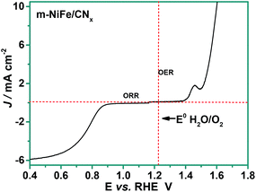 | ||
| Fig. 9 RDE curves of m-NiFe/CNx hybrid in O2-saturated 0.1 M KOH at 1600 rpm as bi-functional catalyst for ORR and OER. | ||
Conclusions
We have successfully developed a simple and convenient method to prepare a conductive mesoporous structure supported NiFe-alloy electrocatalyst. The unique features endow m-NiFe/CNx with outstanding electrocatalytic performance for OER and ORR in terms of activity, kinetics, and stability. The low cost and high catalytic activity of m-NiFe/CNx, together with simple synthesis and the possibility of mass production, may offer a promising avenue to develop alternative catalysts to Ir-based materials for OER in water splitting systems and to Pt-based substances for ORR in fuel cells or metal–air battery systems.Acknowledgements
Financial support for this work was provided by the U.S. Department of Energy (DE-EE0003208), the Research Growth Initiative Program of the University of Wisconsin-Milwaukee (UWM), and the National Natural Science Foundation of China (no. 21206068).Notes and references
- A. J. Bard and M. A. Fox, Acc. Chem. Res., 1995, 28, 141 CrossRef CAS.
- N. S. Lewis, Science, 2007, 315, 798 CrossRef CAS PubMed.
- J. Suntivich, K. J. May, H. A. Gasteiger, J. B. Goodenough and Y. Shao-Horn, Science, 2011, 334, 1383 CrossRef CAS PubMed.
- Y. Surendranath, M. W. Kanan and D. G. Nocera, J. Am. Chem. Soc., 2010, 132, 16501 CrossRef CAS PubMed.
- J. A. Turner, Science, 2004, 305, 972 CrossRef CAS PubMed.
- M. G. Walter, E. L. Warren, J. R. McKone, S. W. Boettcher, Q. Mi, E. A. Santori and N. S. Lewis, Chem. Rev., 2010, 110, 6446 CrossRef CAS PubMed.
- Z. Wei, J. Sun, Y. Li, A. K. Datye and Y. Wang, Chem. Soc. Rev., 2012, 41, 7994 RSC.
- I. Katsounaros, S. Cherevko, A. R. Zeradjanin and K. J. J. Mayrhofer, Angew. Chem., Int. Ed., 2014, 53, 102 CrossRef CAS PubMed.
- J. Lee, B. Jeong and J. D. Ocon, Curr. Appl. Phys., 2013, 13, 309 CrossRef PubMed.
- J. A. Cracknell, K. A. Vincent and F. A. Armstrong, Chem. Rev., 2008, 108, 2439 CrossRef CAS PubMed.
- S. M. Barnett, K. I. Goldberg and J. M. Mayer, Nat. Chem., 2012, 4, 498 CrossRef CAS PubMed.
- J. B. Gerken, J. G. McAlpin, J. Y. C. Chen, M. L. Rigsby, W. H. Casey, R. D. Britt and S. S. Stahl, J. Am. Chem. Soc., 2011, 133, 14431 CrossRef CAS PubMed.
- M. Gong, Y. Li, H. Wang, Y. Liang, J. Z. Wu, J. Zhou, J. Wang, T. Regier, F. Wei and H. Dai, J. Am. Chem. Soc., 2013, 135, 8452 CrossRef CAS PubMed.
- C. C. L. McCrory, S. Jung, J. C. Peters and T. F. Jaramillo, J. Am. Chem. Soc., 2013, 135, 16977 CrossRef CAS PubMed.
- J. Rosen, G. S. Hutchings and F. Jiao, J. Am. Chem. Soc., 2013, 135, 4516 CrossRef CAS PubMed.
- K. Sun, N. Park, Z. Sun, J. Zhou, J. Wang, X. Pang, S. Shen, S. Y. Noh, Y. Jing, S. Jin, P. K. L. Yu and D. Wang, Energy Environ. Sci., 2012, 5, 7872 CAS.
- B. Iandolo, B. Wickman, B. Seger, I. Chorkendorff, I. Zoric and A. Hellman, Phys. Chem. Chem. Phys., 2014, 16, 1271 RSC.
- L. Dai, Acc. Chem. Res., 2013, 46, 31 CrossRef CAS PubMed.
- K. Gong, F. Du, Z. Xia, M. Durstock and L. Dai, Science, 2009, 323, 760 CrossRef CAS PubMed.
- Y. Li, W. Zhou, H. Wang, L. Xie, Y. Liang, F. Wei, J.-C. Idrobo, S. J. Pennycook and H. Dai, Nat. Nanotechnol., 2012, 7, 394 CrossRef CAS PubMed.
- Y. Liang, Y. Li, H. Wang, J. Zhou, J. Wang, T. Regier and H. Dai, Nat. Mater., 2011, 10, 780 CrossRef CAS PubMed.
- S. Wang, E. Iyyamperumal, A. Roy, Y. Xue, D. Yu and L. Dai, Angew. Chem., Int. Ed., 2011, 50, 11756 CrossRef CAS PubMed.
- W. Wei, H. Liang, K. Parvez, X. Zhuang, X. Feng and K. Muellen, Angew. Chem., Int. Ed., 2014, 53, 1570 CrossRef CAS PubMed.
- Z. Wen, S. Ci, F. Zhang, X. Feng, S. Cui, S. Mao, S. Luo, Z. He and J. Chen, Adv. Mater., 2012, 24, 1399 CrossRef CAS PubMed.
- J. Liang, Y. Zheng, J. Chen, J. Liu, D. Hulicova-Jurcakova, M. Jaroniec and S. Z. Qiao, Angew. Chem., Int. Ed., 2012, 51, 3892 CrossRef CAS PubMed.
- Y. Zheng, Y. Jiao, J. Chen, J. Liu, J. Liang, A. Du, W. Zhang, Z. Zhu, S. C. Smith, M. Jaroniec, G. Q. Lu and S. Z. Qiao, J. Am. Chem. Soc., 2011, 133, 20116 CrossRef CAS PubMed.
- J. D. Baran, H. Gronbeck and A. Hellman, J. Am. Chem. Soc., 2014, 136, 1320 CrossRef CAS PubMed.
- S. Mao, Z. Wen, T. Huang, Y. Hou and J. Chen, Energy Environ. Sci., 2014, 7, 609 CAS.
- J. Xu, D. Aili, Q. Li, E. Christensen, J. O. Jensen, W. Zhang, M. K. Hansen, G. Liu, X. Wang and N. J. Bjerrum, Energy Environ. Sci., 2014, 7, 820 CAS.
- A. J. Bard, J. Am. Chem. Soc., 2010, 132, 7559 CrossRef CAS PubMed.
- G. Zhang, Z.-G. Shao, W. Lu, G. Li, F. Liu and B. Yi, Electrochem. Commun., 2012, 22, 145 CrossRef CAS PubMed.
- K. J. J. Mayrhofer, K. Hartl, V. Juhart and M. Arenz, J. Am. Chem. Soc., 2009, 131, 16348 CrossRef CAS PubMed.
- V. R. Stamenkovic, B. S. Mun, M. Arenz, K. J. J. Mayrhofer, C. A. Lucas, G. Wang, P. N. Ross and N. M. Markovic, Nat. Mater., 2007, 6, 241 CrossRef CAS PubMed.
- J. C. Meier, I. Katsounaros, C. Galeano, H. J. Bongard, A. A. Topalov, A. Kostka, A. Karschin, F. Schueth and K. J. J. Mayrhofer, Energy Environ. Sci., 2012, 5, 9319 CAS.
- J. D. Blakemore, N. D. Schley, M. N. Kushner-Lenhoff, A. M. Winter, F. DSouza, R. H. Crabtree and G. W. Brudvig, Inorg. Chem., 2012, 51, 7749 CrossRef CAS PubMed.
- V. K. Puthiyapura, S. Pasupathi, H. Su, X. Liu, B. Pollet and K. Scott, Int. J. Hydrogen Energy, 2014, 39, 1905 CrossRef CAS PubMed.
- Y. Gorlin, B. Lassalle-Kaiser, J. D. Benck, S. Gul, S. M. Webb, V. K. Yachandra, J. Yano and T. F. Jaramillo, J. Am. Chem. Soc., 2013, 135, 8525 CrossRef CAS PubMed.
- Q. Liu, J. Jin and J. Zhang, ACS Appl. Mater. Interfaces, 2013, 5, 5002 CAS.
- Y. J. Sa, K. Kwon, J. Y. Cheon, F. Kleitz and S. H. Joo, J. Mater. Chem. A, 2013, 1, 9992 CAS.
- D. Wang, X. Chen, D. G. Evans and W. Yang, Nanoscale, 2013, 5, 5312 RSC.
- F.-D. Kong, S. Zhang, G.-P. Yin, J. Liu and A.-X. Ling, Catal. Lett., 2014, 144, 242 CrossRef CAS.
- Y. Gorlin and T. F. Jaramillo, J. Am. Chem. Soc., 2010, 132, 13612 CrossRef CAS PubMed.
- W. G. Hardin, D. A. Slanac, X. Wang, S. Dai, K. P. Johnston and K. J. Stevenson, J. Phys. Chem. Lett., 2013, 4, 1254 CrossRef CAS.
- F. Raimondi, G. G. Scherer, R. Kotz and A. Wokaun, Angew. Chem., Int. Ed., 2005, 44, 2190 CrossRef CAS PubMed.
- J.-I. Jung, H. Y. Jeong, J.-S. Lee, M. G. Kim and J. Cho, Angew. Chem., Int. Ed., 2014, 53, 4582 CrossRef CAS PubMed.
- M. Risch, K. A. Stoerzinger, S. Maruyama, W. T. Hong, I. Takeuchi and Y. Shao-Horn, J. Am. Chem. Soc., 2014, 136, 5229 CrossRef CAS PubMed.
- D. Y. Zhao, J. L. Feng, Q. S. Huo, N. Melosh, G. H. Fredrickson, B. F. Chmelka and G. D. Stucky, Science, 1998, 279, 548–552 CrossRef CAS.
- A. Fischer, J. O. Mueller, M. Antonietti and A. Thomas, ACS Nano, 2008, 2, 2489 CrossRef CAS PubMed.
- Y.-S. Jun, W. H. Hong, M. Antonietti and A. Thomas, Adv. Mater., 2009, 21, 4270 CrossRef CAS.
- X.-H. Li and M. Antonietti, Chem. Soc. Rev., 2013, 42, 6593 RSC.
- Y. Shi, Y. Wan, R. Zhang and D. Zhao, Adv. Funct. Mater., 2008, 18, 2436 CrossRef CAS.
Footnotes |
| † Electronic supplementary information (ESI) available: Characterization of the reference sample and some additional electrochemical results. See DOI: 10.1039/c5ta00894h |
| ‡ These authors contributed equally. |
| This journal is © The Royal Society of Chemistry 2015 |

