Synthesis, structure, and conduction mechanism of the lithium superionic conductor Li10+δGe1+δP2−δS12†
Received
2nd October 2014
, Accepted 4th November 2014
First published on 19th November 2014
Abstract
A solid solution of the lithium superionic conductor Li10+δGe1+δP2−δS12 (0 ≤ δ ≤ 0.35) was synthesized and its structure and ionic conductivity were examined. The highest ionic conductivity value of 1.42 × 10⁻² S cm−1 was obtained at 300 K with a sintered pellet of the sample having the highest solid solution lithium content of δ = 0.35. The Arrhenius conductivity curves obtained for this material exhibited a gradual change in slope over the temperature range of 193–373 K and the activation energy for ionic conduction decreased from 26 kJ mol−1 below 373 K to 7 kJ mol−1 above 573 K, which is typical of highly ionic conducting solids. The crystal structures of the solid solutions were determined using neutron diffraction, and conduction pathways were visualized through analysis by applying the maximum entropy method. The lithium distribution was found to disperse significantly throughout a one-dimensional conduction pathway as the temperature was increased from 4.8 K to 750 K. In addition, two-dimensional distribution of lithium along the ab plane became apparent at high temperatures, suggesting that the conduction mechanism changes from one-dimensional to three-dimensional with increasing temperature.
1. Introduction
Among the various types of batteries currently under consideration for future applications, the all-solid-state configuration has become a promising candidate for high-energy and high-power-density batteries.1–3 The development of materials capable of acting as fast ionic conductors, which can thus be used as solid electrolytes, will play a key role in the realization of these battery systems. The lithium ionic conductor Li10GeP2S12 (LGPS) exhibits extremely high ionic conduction at room temperature, on the order of 10−2 S cm−1, a value that is comparable to or much higher than the conductivity values of organic liquid electrolytes such as the ethylene carbonate (EC)/propylene carbonate (PC) system.4–6 All solid-state batteries incorporating solid electrolytes show excellent charge–discharge characteristics,4 and these power characteristics have been found to be affected by the ionic conductivity of the solid electrolyte, such that higher ionic conductivity leads to significant improvements in the discharge rate of the device.2,4
Although inorganic solid electrolytes offering extremely high lithium ionic conductivities have been developed, further studies clarifying the conduction mechanism and increasing the range of electrolyte materials are still necessary to allow the practical applications of these electrolytes. LGPS is known to have a three-dimensional framework structure composed of one-dimensional chains formed by Ge(P)S4 tetrahedra and LiS6 octahedra with edge sharing along the c direction of the tetragonal structure. These one-dimensional chains are connected with each other through PS4 octahedra by corner sharing. Within this framework structure, lithium occupies the tetrahedral sites along the c direction, and the results of neutron diffraction studies have suggested that this contributes to the ionic conduction process. Theoretical analyses based on first-principles calculations have indicated the presence of a two-dimensional conduction pathway through lithium in the octahedral coordination environment.7,8
Following the development of this LGPS-type parent structure having extremely high ionic conductivity,9–12 it was recognized that similar solid solution systems with different lithium contents might exhibit even higher levels of ionic conduction. In addition, cation and anion substitutions of the LGPS framework structure are also important means of achieving higher ionic conductivity values. In the present study, a solid solution with an LGPS-type structure was produced based on a powder synthesis process that offers a practical means of fabricating solid electrolytes. The composition and ionic conductivity of this new solid solution system, Li10+δGe1+δP2−δS12, were subsequently examined and the conduction mechanism within this material was studied using neutron diffraction analysis.
2. Experimental
The LPGS solid solution was synthesized using a solid-state reaction. In this process, mixtures of P2S5 (Aldrich, 99% purity), Li2S (Nihon Kagaku Kogyo, >99.9% purity), and GeS2 (Kojundo Chemical Laboratory Co., Ltd., >99.99% purity) were ground in a vibrating mill (CMT, Tl-100) for 30 min, pelletized under 220 MPa pressure, sealed in a silica tube at 30 Pa, and heated at 673 K for 8 h with 2.2 K min−1 heating rate and 0.60 K min−1 cooling rate. The resulting products were again subjected to grinding and mixing, after which the samples were once again pelletized under 220 MPa, followed by heat treatment at 823 K for 8 h with 3.0 K min−1 heating rate and 0.76 K min−1 cooling rate. Ionic conductivity values were measured using samples approximately 10 mm in diameter and 2–3 mm in height which had been pelletized under 165 MPa and sintered at 873 K for 8 h with 3.3 K min−1 heating rate and 0.83 K min−1 cooling rate. Au powder was coated on the surfaces of samples. The AC impedance values of samples were measured using a frequency response analyzer (National Instrument, nF) by applying 10 mV over the frequency range of 100 Hz to 15 MHz.
X-ray diffraction patterns of the powdered samples were obtained using an X-ray diffractometer (Rigaku, RAD, Ultima or Smart Lab) with CuKα radiation. The diffraction data were collected by applying a 0.02° step width over the 2θ range from 10° to 80°. Synchrotron X-ray diffraction measurements were performed at the BL02B2 beamline at Spring-8 in Japan, employing a Debye–Scherrer diffraction camera. Specimens were sealed in a quartz capillary (about 0.3 mm diameter) under vacuum. Diffraction data were collected in 0.01° steps over the 2θ range of 0° to 70.0°. The incident beam wavelength was calibrated using a NIST SRM Ceria 640b CeO2 and fixed at 0.59960 Å. Neutron diffraction data were obtained using time-of-flight (TOF) diffractometers: Super HRPD (BL08)13 and iMATERIA (BL20)13,14 at the Material and Life science Facility (MLF) of the Japan Proton Accelerator Research Complex (J-PARC). A 6 mm diameter vanadium cell was used and samples were sealed with an indium ring under Ar or He atmospheres. The diffraction data were collected for 12 h at several temperatures: Li10.5Ge1.5P1.5S12: 300 K, Li10.35Ge1.35P1.65S12: 4.8, 135, and 300 K, Li10.2Ge1.2P1.8S12: 300 K and Li10.05Ge1.05P1.95S12: 10, 135, 300, 450, and 750 K. Structural parameters were refined using the Rietveld refinement programs Z-Rietveld15 and RIETAN-FP16,17 for neutron and for high-flux synchrotron X-ray diffraction data, respectively. During neutron data analysis, the d region from 1.0 to 3.5 Å was used for the Rietveld analysis. The Z-MEM program was employed during calculations based on the maximum entropy method (MEM).18 Z-3D19 was used to visualize the nuclear density map of the structure.
3. Results and discussion
3.1. Synthesis of the solid solution
The LGPS solid solutions fabricated during this study were based on the Li3PS4–Li4GeS4 pseudo-binary system and compositions similar to the parent LGPS (Li10GeP2S12) phase were synthesized according to the compositional formula Li10+δGe1+δP2−δS12. Fig. 1(a) shows the X-ray diffraction patterns of the Li10+δGe1+δP2−δS12 compounds synthesized in the present study. The monophasic character of the LGPS phase was observed in those materials in which δ was at or near zero, with a continuous peak shift to lower angles with increasing values of δ, suggesting the formation of a solid solution in the LGPS phase. The lattice parameters were calculated by Rietveld analysis based on the space group P42/nmc4 using the synchrotron X-ray diffraction data. Fig. 1(b) shows the lattice parameter changes with the composition of the LGPS phase. The lattice parameters are observed to increase with increasing δ values from zero to 0.50, indicating the formation of a solid solution. A small amount of a Li4GeS4 impurity phase is observed at δ ≥ 0.65 in the Li10+δGe1+δP2−δS12, while a β-Li3PS4-type phase (Thio-LISICON phase) is seen in those compositions in which δ ≤ −0.10. The compositional range of the solid solution in the Li10+δGe1+δP2−δS12 LGPS phase was determined to span the range 0 ≤ δ ≤ 0.50. The increase in both the lattice parameters and the volume with increasing δ values in Li10+δGe1+δP2−δS12 over the range of 0 ≤ δ ≤ 0.50 is attributed to an increase in the Ge4+ (0.390 Å)/P5+ (0.17 Å) ratio in the structure.20
 |
| | Fig. 1 (a) X-ray diffraction patterns of Li10+δGe1+δP2−δS12 (−0.10 ≤ δ ≤ 0.50) (0.50 ≤ x ≤ 0.70 in Li4−xGe1−xPxS4). A single LGPS phase was obtained for the compositions in which 0 ≤ δ ≤ 0.35 (0.55 ≤ x ≤ 0.67 in Li4−xGe1−xPxS4), while β-Li3PS4-type and Li4GeS4-type phases were observed in materials in which δ < 0 and δ > 0.35 (x > 0.67 and x < 0.55), respectively. (b) Lattice parameters of Li10+δGe1+δP2−δS12 (0 ≤ δ ≤ 0.50) (0.50 ≤ x ≤ 0.67 in Li4−xGe1−xPxS4) as calculated from synchrotron X-ray diffraction measurements at 300 K. | |
3.2. Ionic conductivity
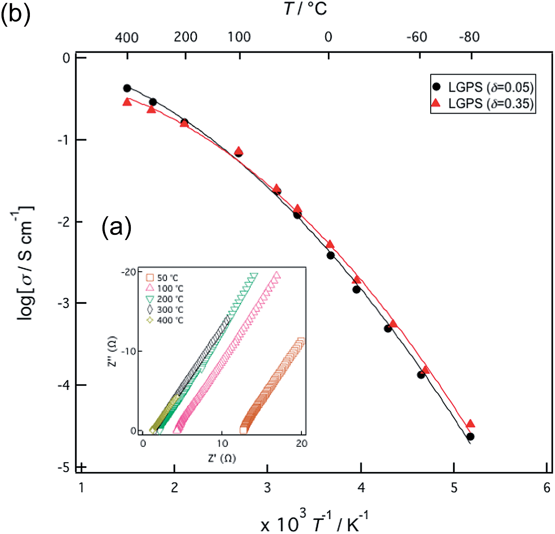
Fig. 2(a) presents typical impedance plots obtained from the solid solutions in the form of sintered pellets at various temperatures. These plots only exhibit a spike in the low frequency region, corresponding to the contributions of the electrode components.21 As the contributions from the bulk and grain boundary components could not be separated in the temperature range measured during the present study, the reported conductivity values represent the sum total of the grain and bulk contributions. Fig. 2(b) shows Arrhenius plots of the conductivity values measured for two solid solutions. No differences in conductivity were observed during the heating and cooling of both samples, demonstrating that these compositions are stable over the temperature range measured in the present study. The highest ionic conductivity value of 1.42 × 10⁻² S cm−1 at 300 K was obtained for the composition in which δ was 0.35 and this conductivity exceeds the value of 1.20 × 10⁻² S cm−1 reported previously for such materials.4 The activation energies calculated over the temperature range of 193–373 K for the compositions with δ values of 0.05 and 0.35 were 27 and 26 kJ mol−1, respectively. At temperatures above 373 K, the Arrhenius plots exhibit a change in slope and the activation energy values calculated between 573 and 673 K decrease to 12 and 7 kJ mol−1 for the same compositions. The decrease in the activation energy at higher temperatures is a well-known phenomenon associated with highly ionic conducting solids and is sometimes referred to as a diffuse phase transition,22 although it is not yet clearly understood. The LGPS solid solutions show an extremely high ionic conduction state above 373 K.
 |
| | Fig. 2 (a) Impedance plots obtained for Li10+δGe1+δP2−δS12 (δ = 0.35) over a range of temperatures. (b) Arrhenius plots of the ionic conductivity values of Li10+δGe1+δP2−δS12 (δ = 0.05 and 0.35). | |
When assessing the practical applicability of highly ionic conducting materials as solid electrolytes in all solid-state batteries, the conductivity of pressed pellets of the powdered samples is one of the most important parameters in terms of estimating the resistivity of composite electrodes and electrolytes. The ionic conductivity values of pressed powder samples were therefore measured at room temperature. The samples were each pressed under a pressure of 165 MPa and their conductivity values were determined using the AC impedance method. The impedance plots were each composed of a semi-circular region and a spike, corresponding respectively to the bulk/grain boundary and electrode contributions. In this respect, the plots were similar to those produced by sintered pellets and the conductivity values of the bulk/grain boundary are plotted as a function of the composition in Fig. 3. The conductivity values are seen to change with variations in the composition, and the highest ionic conductivity of 6.09 × 10⁻³ S cm−1 was obtained at a δ value of 0.35, corresponding to the sintered pellet composition that exhibited the highest conductivity. On the other hand, the ionic conductivity of δ = 0.50, which is expected to be the highest value, showed a lower value than that expected in the solid solution. This might originate from a small amount of impurities such as β-Li3PS4, although it is hardly detected by XRD.
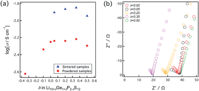 |
| | Fig. 3 (a) Dependence of room temperature ionic conductivities of pressed powder samples on composition. (b) Room temperature impedance plots obtained for powder samples. | |
3.3. Structural analysis using neutron diffraction data
Structural analysis was carried out based on a previously reported model incorporating three lithium sites (Li1 at 16h: x, y, z; Li2 at 4d: 1, 1/2, z, Li3 at 8f: x, x, 0), together with an Li4 site (Li4 at 4c: 0, 0, z) proposed as the result of molecular dynamics simulations.23 The existence of the Li4 site was assessed using the neutron diffraction data acquired at 4.8 K for Li10.35Ge1.35P1.65S12 and the difference in the Fourier map confirmed the presence of lithium at this site. The structural models incorporating the Li4 site in Li10.35Ge1.35P1.65S12 (δ = 0.35) and Li10.05Ge1.05P1.95S12 (δ = 0.05) also provided lower structural reliability (R) factors than those without the Li4 site; for example, S2 and Rwp values were improved from 2.03 and 3.43% to 1.75 and 3.06%, respectively. Table 1 summarizes the R factors and the refined parameters for Li10.35Ge1.35P1.65S12 at room temperature, while Fig. 4 provides the Rietveld refinement pattern obtained for Li10.35Ge1.35P1.65S12 at 300 K as an example (Table 2).
Table 1 Comparison of reliability factors for Li10.35Ge1.35P1.65S12 (δ = 0.35) at 300 K
|
|
Model with a Li4 site |
Model without a Li4 site |
|
R
wp
|
3.06% |
3.43% |
|
R
p
|
2.52% |
2.77% |
|
R
e
|
2.32% |
2.41% |
|
R
b
|
8.58% |
11.0% |
|
R
F
|
5.83% |
8.25% |
|
S
2
|
1.75 |
2.03 |
 |
| | Fig. 4 Neutron Rietveld refinement pattern of Li10.35Ge1.35P1.65S12 at 300 K. Red: observed intensities; black: calculated intensities; blue: difference plot. The green markers indicate the positions of the diffraction lines. | |
Table 2 Rietveld refinement results for Li10.35Ge1.35P1.65S12 (δ = 0.35) at 300 Ka
| Atom |
Site |
g
|
x
|
y
|
z
|
U/Å2 |
|
Space group P42/nmc, a = 8.713023 (5) Å, c = 12.639695 (11) Å, Rwp = 3.06%, Rp = 2.52%. Note: the form of the anisotropic temperature factor is exp[−2p2(h2a*2U11 + k2b*2U22 + l2c*2U33 + 2hka*b*U11 + 2hla*c*U13 + 2klb*c*U23)].
|
| Ge(1) |
4d |
0.675 (12) |
0 |
1/2 |
0.6885 (10) |
0.046 |
| P(1) |
4d |
0.325 (12) |
= x(Ge1) |
= y(Ge1) |
= z(Ge1) |
= B(Ge1) |
| Ge(2) |
2b |
0.00 (2) |
0 |
0 |
1/2 |
0.046 |
| P(2) |
2b |
1.00 (2) |
= x(Ge2) |
= y(Ge2) |
= z(Ge2) |
= B(Ge2) |
| S(1) |
8g |
1 |
0 |
0.1920 (2) |
0.4090 (2) |
0.046 |
| S(2) |
8g |
1 |
0 |
0.2958 (2) |
0.0989 (2) |
0.048 |
| S(3) |
8g |
1 |
0 |
0.7005 (3) |
0.7885 (2) |
0.035 |
| Li(1) |
16h |
0.473 (11) |
0.2477 (9) |
0.2616 (13) |
0.2018 (11) |
0.108 |
| Li(2) |
4d |
1 |
0 |
1/2 |
0.9524 (4) |
0.060 |
| Li(3) |
8f |
0.75 (2) |
= y(Li3) |
0.2463 (4) |
0 |
0.118 |
| Li(4) |
4c |
0.77 (2) |
0 |
0 |
0.2585 (7) |
0.077 |
| Atom |
U
11/Å2 |
U
22/Å2 |
U
33/Å2 |
U
12/Å2 |
U
13/Å2 |
U
23/Å2 |
| Ge(1) |
0.052 (10) |
0.044 (14) |
0.043 (13) |
0 |
0 |
0 |
| P(1) |
= U11(Ge1) |
= U22(Ge1) |
= U33(Ge1) |
= U12(Ge1) |
= U13(Ge1) |
= U23(Ge1) |
| Ge(2) |
= U22(Ge2) |
0.038 (11) |
0.062 (3) |
0 |
0 |
0 |
| P(2) |
= U11(Ge2) |
= U22(Ge2) |
= U33(Ge2) |
= U12(Ge2) |
= U13(Ge2) |
= U23(Ge2) |
| S(1) |
0.078 (2) |
0.023 (2) |
0.038 (3) |
0 |
0 |
0.014 (10) |
| S(2) |
0.055 (2) |
0.036 (2) |
0.052 (3) |
0 |
0 |
−0.010 (10) |
| S(3) |
0.044 (2) |
0.009 (2) |
0.052 (2) |
0 |
0 |
0.002 (2) |
| Li(1) |
0.074 (8) |
0.050 (8) |
0.20 (2) |
0.019 |
−0.097 (11) |
−0.059 (11) |
| Li(2) |
0.104 (4) |
0.051(6) |
0.024 (5) |
0 |
0 |
0 |
| Li(3) |
= U22(Li3) |
0.048 (5) |
0.259 (11) |
−0.0335 (3) |
= −U23(Li3) |
−0.0929 (4) |
| Li(4) |
0.026 (9) |
0.096 (11) |
0.108 (10) |
0 |
0 |
0 |
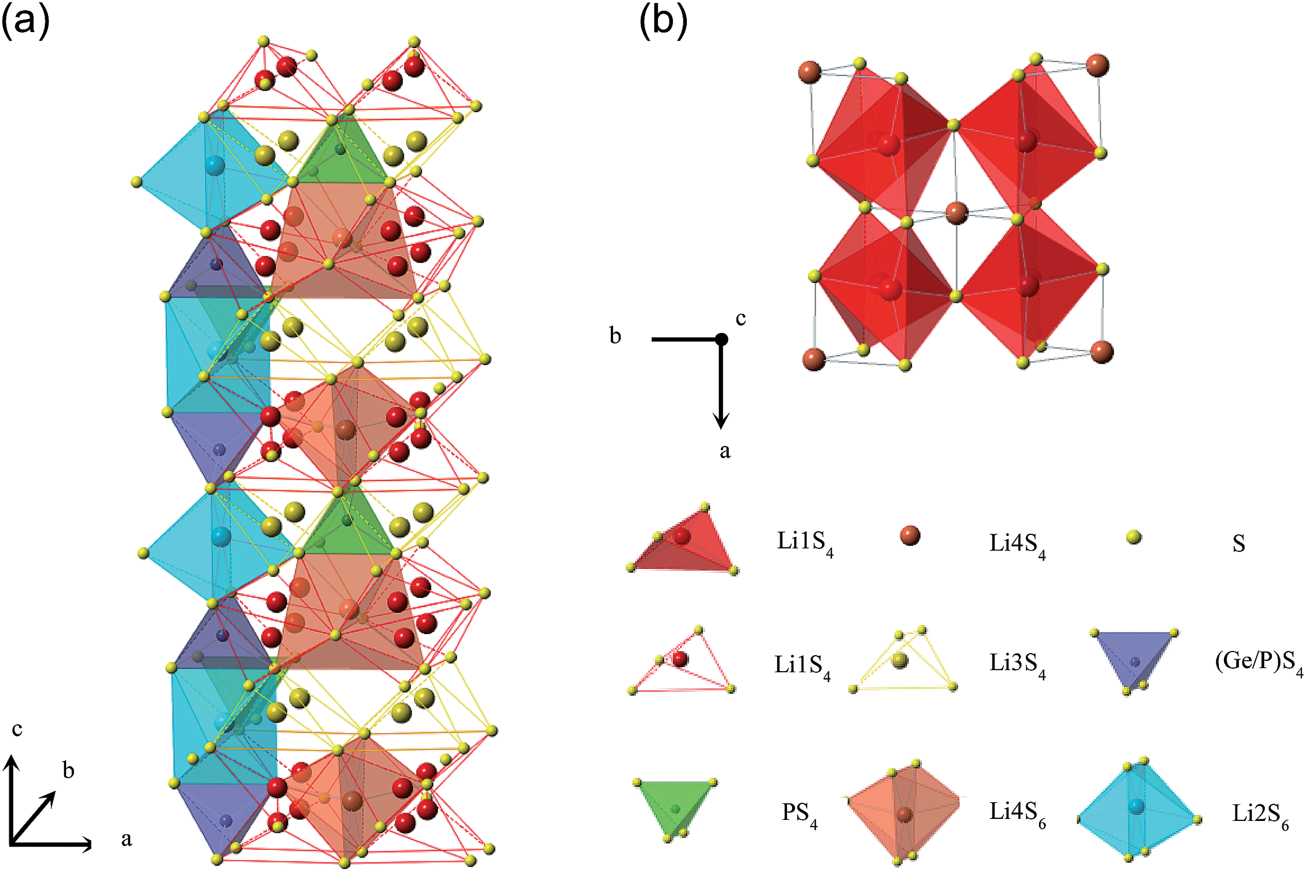
Fig. 5 provides the structure of Li10.35Ge1.35P1.65S12 (δ = 0.35) as determined in the present study. At δ = 0.35, the 4d site is occupied by Ge and P with a Ge/P ratio of 0.675/0.325. The framework of Li10GeP2S12 is composed of (Ge/P)S4 tetrahedra and Li2S6 octahedra in 4d sites, connected to one another by edge sharing. The one-dimensional connections between the Li1S4 and Li3S4 tetrahedra are located at the 16h and 8f sites, forming a one-dimensional tunnel along the c-axis. The Li4 site introduced in this study is located at the 4c site with a fractional coordinate (z ∼ 0.2585) and the Li4 is connected to six sulfide ions with distances of 2.5(Li4–S1), 2.7(Li4–S2), and 3.3 (Li4–S3) Å and is situated near the center of eight Li1 sites (see Fig. 5) with distances between the Li1 and Li4 sites being 3.2 (× 4) and 3.1 (× 4) Å. The Li4S6 octahedra are also connected to PS4 tetrahedra by edge sharing along the c direction and to four Li2S6 octahedra and two Ge1S4 tetrahedra by corner sharing.
 |
| | Fig. 5 (a) Structure of Li10+δGe1+δP2−δS12. Li2(4d)S6 octahedra and (Ge/P)(4d)S4 tetrahedra form a one-dimensional framework with P(2b)S4 tetrahedra situated between the Li2S6 octahedra by corner sharing to connect the one-dimensional chains, thus forming a three-dimensional framework structure. (b) Coordination of Li4(4c)S6 octahedra within the structure. Each Li4(4c)S6 octahedron shares its four edges with Li1(16h)S4 tetrahedral sites. | |
3.4. Ionic conduction mechanism
The lithium conduction mechanism was investigated based on neutron diffraction analysis. After a one-dimensional conduction pathway was proposed along the c-axis,4 three-dimensional conduction together with the one-dimensional pathway was indicated8,23 based on the results of molecular dynamics (MD) simulations. Furthermore, recent single-crystal analysis using X-ray diffraction has indicated that three-dimensional motion of lithium ions contributes to the ionic conduction.24Fig. 6 shows the effects of variation in composition on the occupation parameter, g, at each Li site in Li10+δGe1+δP2−δS12. The g value of the Li1 site increased while those of the Li3 and Li4 sites decreased with increasing values of δ. These behaviors indicate that the lithium ion distribution at these sites changes with the lithium ion distributions that are associated with higher lithium composition and more highly disordered (or uniform) contents. This may correspond to slightly higher lithium ionic conduction for the composition in which δ = 0.35. The total amount of lithium distributed along the Li1 and Li3 conduction pathways increased from 12.7 to 13.5 with increasing values of δ from zero to 0.35. Slightly higher ionic conductivity was observed for the composition in which δ = 0.35 and this might be the result of a higher amount of lithium in the one-dimensional conduction pathway in the structure.
 |
| | Fig. 6 The occupation parameter, g, at each Li site in Li10+δGe1+δP2−δS12 as a function of δ. The values at δ = 0.0 are taken from ref. 4. | |
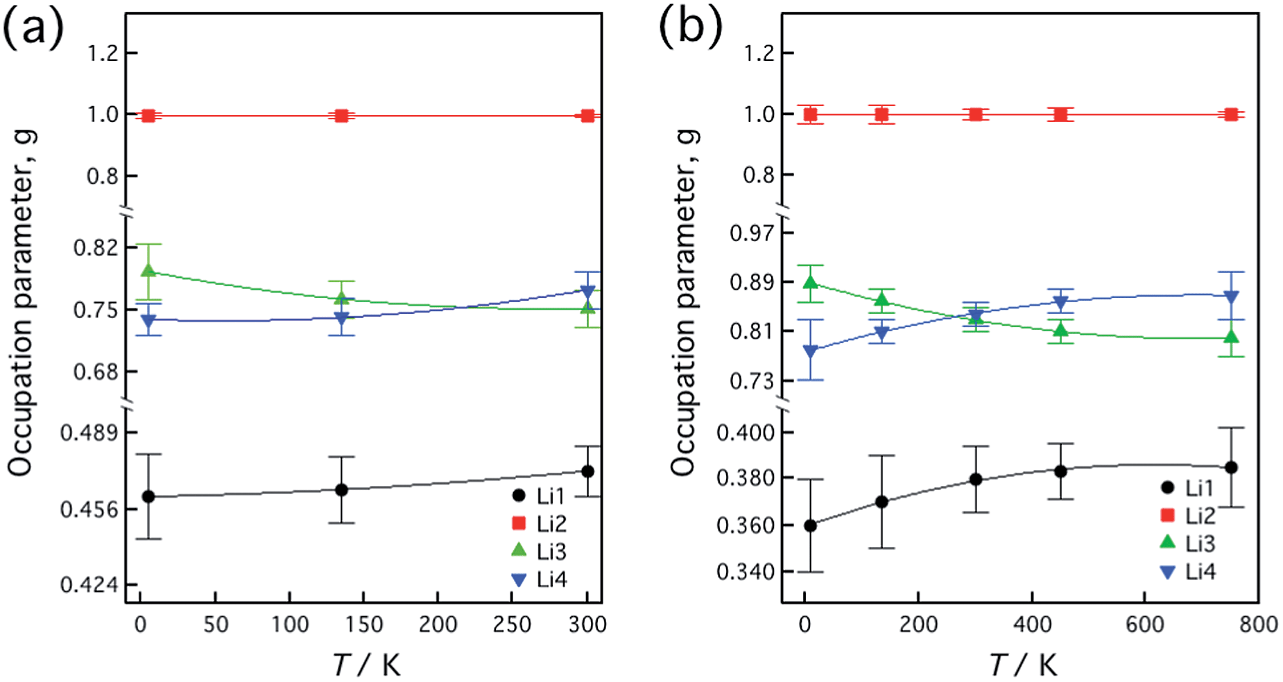
The temperature dependencies of the lattice parameters were assessed for the compositions in which δ = 0.05 and 0.35, based on synchrotron X-ray diffraction and neutron diffraction analyses. Fig. 7 shows the lattice parameter changes with temperature for both samples. The lattice parameters and the volume are seen to have increased with increasing temperature up to 750 K, although no significant phase changes were observed. Fig. 8 shows the temperature dependence of the occupation parameter, g, at each Li site in Li10.35Ge1.35P1.65S12 and Li10.05Ge1.05P1.95S12, as measured over the temperature ranges of 4.8–300 K and 10–750 K, respectively. For both compositions, the g value at the Li2 site was constant at 1.0 throughout the entire temperature range, indicating that the Li2 sites form a framework structure with the GeS4 and PS4 tetrahedra. In contrast, the g values of the Li1 and Li4 sites increased while that of the Li3 site decreased with increasing temperature. These slight changes in the occupation parameters with temperature may suggest that these sites contribute to the lithium ionic conduction. The g value of the Li3 site decreased and that of the Li1 site increased with increasing temperature, which corresponds to more highly disordered lithium distributions at higher temperatures. The temperature dependence of the total quantity of lithium ions in the unit cell was calculated by the MD simulation method23 and the occupation parameters and thermal evolution of these parameters were found to be quite consistent with those determined for the composition Li10.35Ge1.35P1.65S12 based on neutron diffraction data.
 |
| | Fig. 7 Temperature dependencies of Li10+δGe1+δP2−δS12 (δ = 0.05 and 0.35) (x = 0.55 and 0.65 in Li4−xGe1−xPxS4) lattice parameters, as calculated from neutron diffraction measurements. The temperature ranges for the δ = 0.05 and 0.35 materials were 4.8 K ≤ T ≤ 300 K and 10 K ≤ T ≤ 750 K, respectively. | |
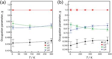 |
| | Fig. 8 The occupation parameter, g, at each Li site in (a) Li10.35Ge1.35P1.65S12 (δ = 0.35 in Li10+δGe1+δP2−δS12) and (b) Li10.05Ge1.05P1.95S12 (δ = 0.05 in Li10+δGe1+δP2−δS12) as a function of temperature over the ranges of 4.8–300 K and 10–750 K, respectively. | |
Fig. 9 shows the temperature dependence of the isotropic displacement parameter of each Li site in Li10.35Ge1.35P1.65S12 (δ = 0.35) and Li10.05Ge1.05P1.95S12 (δ = 0.05), as assessed over the temperature ranges of 4.8–300 K and 10–750 K, respectively. These isotropic displacement parameters were calculated from the final anisotropic displacement parameters. For both compositions, the B values at the Li2 site were lower than those of the other Li sites, indicating that the Li2 sites form the framework structure along with the GeS4 and PS4 tetrahedra.
 |
| | Fig. 9 Temperature dependencies of the isotropic displacement parameters of each Li site in (a) Li10.35Ge1.35P1.65S12 (δ = 0.35) and (b) Li10.05Ge1.05P1.95S12 (δ = 0.05), as measured over the temperature ranges of 4.8–300 K and 10–750 K, respectively. | |
The B values of the Li1 and Li3 sites increase with temperature from 4.8–10 K to 300 K and become almost constant above 300 K. These behaviors are consistent with the previous indications that these two sites participate in lithium ionic conduction within the structure. Higher B values at these Li1 and Li3 sites also suggest that these sites make a contribution to Li ion conduction. In contrast, the B value of the Li4 site increases from 10 to 300 K and becomes quite a high value at 750 K, and so the Li4 site is expected to play a significant role in ionic conduction at high temperatures.
Fig. 10 presents the temperature dependencies of the atomic distances between Li1 and Li1, and Li1 and Li3 for the compositions of Li10.35Ge1.35P1.65S12 (δ = 0.35) and Li10.05Ge1.05P1.95S12 (δ = 0.05). In the case of both compositions, the Li1–Li1 distances decrease and the Li1–Li3 distances increase with increasing temperature. The Li1–Li1 distance approaches 1.3 Å at 300 and 750 K for the δ = 0.05 and 0.35 materials, a value that is close to twice the Li+ ionic radius in tetrahedral coordination (0.59 Å),20 suggesting that these two Li sites are situated close to one another. The increase in the occupation parameter at the Li1 site and the decrease in the Li1–Li1 distance with increasing temperature point to an elevated extent of lithium disordering along these Li1 sites. The decrease in the g parameters at the Li3 sites and the increase in the Li4 and Li1 sites with an expansion of the Li1–Li3 distance might correspond to a lithium site change from the Li3 to the Li1 and Li4 sites. This result indicates that the conduction mechanism changes from a one-dimensional –Li1–Li3–Li1–Li1– pathway to a two-dimensional –Li1–Li4–Li1–Li1– pathway. However, the thermal parameters associated with the Li1 and Li3 sites are larger than those of the Li4 sites below 300 K, which may indicate that the one-dimensional conduction pathway is still dominant below room temperature.
 |
| | Fig. 10 Temperature dependencies of the atomic distances between Li1 and Li1, and Li1 and Li3 for the compositions Li10.35Ge1.35P1.65S12 (δ = 0.35) and Li10.05Ge1.05P1.95S12 (δ = 0.05). | |
Lithium ion distribution was visualized using the MEM analysis in conjunction with the neutron diffraction data obtained for Li10.05Ge1.05P1.95S12 (δ = 0.05) (x = 0.65 in Li4−xGe1−xPxS4) at 100 and 750 K. Fig. 11 shows the atomic distribution in the unit cell, in which the probability of an atom being present is represented only for the negative scattering powers, which corresponds to the lithium ion distribution in the unit cell. These probabilities were calculated using an iso-surface level of 0.08 for the structure at both temperatures. At 100 K, the Li1, Li1, and Li3 sites are connected along the c-axis, while the other lithium sites (the Li2 and Li4 sites) are isolated from each other. This indicates that the one-dimensional conduction pathway represents the primary means of lithium ion conduction at 100 K. The one-dimensional conduction pathway along the c-axis becomes more evident at 750 K. In addition to the one-dimensional connection between the Li1, Li1, and Li3 sites, continuous lithium distribution between the Li1 and Li4 sites is also now observed. These results demonstrate that the lithium ion conduction takes on a three-dimensional character, as opposed to one-dimensional, at higher temperatures. The existence of three-dimensional ionic conduction at high temperatures is consistent with the observed atomic distribution and thermal parameter changes at each lithium site. Thus the LGPS-type structure is evidently well-suited to three-dimensional conduction. Even though one-dimensional conduction is dominant at lower temperatures, the conduction pathway associated with Li1 and Li4 sites over the ab plane becomes evident at high temperatures. These conduction behaviors are also consistent with the previously reported results of MD simulation studies.23 Isotropic ionic diffusion in a solid electrolyte is favorable in terms of practical application of the material in an all solid-state battery, since anisotropic ionic diffusion may prevent high ionic diffusion between the electrolyte and the electrode particles and thus reduce the ability of the solid-state cell to generate current. The LGPS structure is therefore suitable for practical applications, such as in all solid-state batteries.
 |
| | Fig. 11 Atomic distributions in the Li10.05Ge1.05P1.95S12 (δ = 0.05) unit cell at 100 K (a) and 750 K (b). The probability of an atom being present is indicated only for the negative scattering powers, which correspond to the lithium ion distribution in the unit cell. | |
4. Conclusions
A solid solution of the lithium superionic conductor Li10+δGe1+δP2−δS12 (0 ≤ δ ≤ 0.35) was synthesized and its structure and ionic conductivity were determined. An ionic conductivity value of 1.42 × 10⁻² S cm−1 was obtained at 300 K for sintered pellets of the sample in which δ = 0.35. The Arrhenius plots of the conductivity show a change in slope at high temperatures, at which the activation energy for ionic conduction decreases to approximately 10 kJ mol−1, which is characteristic of highly ionic conducting solids. The ionic conduction mechanism determined by neutron diffraction measurements indicates a change in the conduction pathway with increasing temperatures, such that a one-dimensional pathway transitions to a three-dimensional mechanism at elevated temperatures. The lithium diffusion pathway visualized through MEM analysis assisted in elucidating the conductivity pathway changes with temperature. The isotropic ionic conducting characteristics of the LGPS structure may mean that related structures of this material are suitable for practical applications in all-solid-state batteries.
Acknowledgements
This research was supported by the Post-LiEAD project of the New Energy and Industrial Technology Development Organization (NEDO), Japan. The program used for the MEM analysis was developed through the support of the RISING project of NEDO. Synchrotron and neutron radiation data were obtained through projects approved by the Japan Synchrotron Radiation Research Institute (JASRI) (Proposal nos 2011A1612 and 2011B1697) and the Japan Proton Accelerator Research Complex (J-Parc) (Proposal nos 2010B0065, 2012A0107, 2012B0110, and 2013A0133).
Notes and references
- X. Xu, K. Takada, K. Watanabe, I. Sakaguchi, K. Akatsuka, B. T. Hang, T. Ohnishi and T. Sasaki, Chem. Mater., 2011, 23, 3798 CrossRef CAS.
- Y. Kato, K. Kawamoto, R. Kanno and M. Hirayama, Electrochemistry, 2012, 80, 749 CrossRef CAS.
- T. Ohtomo, A. Hayashi, M. Tatsumisago, Y. Tsuchida, S. Hama and K. Kawamoto, J. Power Sources, 2013, 233, 231 CrossRef CAS.
- N. Kamaya, K. Homma, Y. Yamakawa, M. Hirayama, R. Kanno, M. Yonemura, T. Kamiyama, Y. Kato, S. Hama, K. Kawamoto and A. Mitsui, Nat. Mater., 2011, 10, 682 CrossRef CAS.
- P. E. Stallworth, J. J. Fontanella, M. C. Wintersgill, C. D. Scheidler, J. J. Immel, S. G. Greenbaum and A. S. Gozdz, J. Power Sources, 1999, 81–82, 739 CrossRef CAS.
- B. Garcia, S. Lavallée, G. Perron, C. Michot and M. Armand, Electrochim. Acta, 2004, 49, 4583 CrossRef CAS.
- F. Du, X. Ren, J. Yang, J. Liu and W. Zhang, J. Phys. Chem. C, 2014, 118, 10590 CAS.
- Y. Mo, S. P. Ong and G. Ceder, Chem. Mater., 2012, 24, 15 CrossRef CAS.
- P. Bron, S. Johansson, K. Zick, J. Schmedt auf der Gunne, S. Dehnen and B. Roling, J. Am. Chem. Soc., 2013, 135, 15694 CrossRef CAS.
- Y. Kato, R. Saito, M. Sakano, A. Mitsui, M. Hirayama and R. Kanno, J. Power Sources, 2014, 271, 60 CrossRef CAS.
- S. Hori, K. Suzuki, M. Hirayama, Y. Kato, T. Saitoo, M. Yonemura and R. Kanno, Faraday Discuss., 2014 10.1039/C4FD00143E.
- A. Kuhn, O. Gerbig, C. Zhu, F. Falkenberg, J. Maier and B. V. Lotsch, Phys. Chem. Chem. Phys., 2014, 16, 14669 RSC.
- S. Torii, M. Yonemura, T. Yulius Surya Panca Putra, J. Zhang, P. Miao, T. Muroya, R. Tomiyasu, T. Morishima, S. Sato, H. Sagehashi, Y. Noda and T. Kamiyama, J. Phys. Soc. Jpn., 2011, 80, SB020 CrossRef.
- T. Ishigaki, A. Hoshikawa, M. Yonemura, T. Morishima, T. Kamiyama, R. Oishi, K. Aizawa, T. Sakuma, Y. Tomota, M. Arai, M. Hayashi, K. Ebata, Y. Takano, K. Komatsuzaki, H. Asano, Y. Takano and T. Kasao, Nucl. Instrum. Methods Phys. Res., Sect. A, 2009, 600, 189 CrossRef CAS PubMed.
- R. Oishi, M. Yonemura, Y. Nishimaki, S. Torii, A. Hoshikawa, T. Ishigaki, T. Morishima, K. Mori and T. Kamiyama, Nucl. Instrum. Methods Phys. Res., Sect. A, 2009, 600, 94 CrossRef CAS PubMed.
- F. Izumi and K. Momma, J. Vac. Soc. Jpn., 2010, 53, 706 CrossRef CAS.
- F. Izumi and K. Momma, Solid State Phenom., 2007, 130, 15 CrossRef CAS.
-
J. Zhang, R. Kiyanagi, M. Yonemura, Y. Ishikawa and T. Kamiyama, Z-MEM, Textbook of Z-code Powder Diffraction Data Analysis School, Japan, Tokyo, March 25–26, 2014 Search PubMed.
-
Y. Ishikawa, M. Yonemura and T. Kamiyama, Z-3D, Textbook of Z-code Powder Diffraction Data Analysis School, Japan, Tokyo, March 25–26, 2014 Search PubMed.
- R. D. Shannon and C. T. Prewitt, Acta Crystallogr., Sect. B: Struct. Crystallogr. Cryst. Chem., 1969, 25, 925 CrossRef CAS.
-
A. R. West, in Solid State Chemistry and its Applications, John Wiley & Sons, Chichester, U. K., 2nd edn, 1988, ch. 13.3.2, p. 482 Search PubMed.
- A. V. Chadwick, Solid State Ionics, 1983, 8, 209 CrossRef CAS.
- S. Adams and R. Prasada Rao, J. Mater. Chem., 2012, 22, 7687 RSC.
- A. Kuhn, J. Kohler and B. V. Lotsch, Phys. Chem. Chem. Phys., 2013, 15, 11620 RSC.
Footnote |
| † Electronic supplementary information (ESI) available. CCDC 1027666. For ESI and crystallographic data in CIF or other electronic format see DOI: 10.1039/c4ta05231e |
|
| This journal is © The Royal Society of Chemistry 2015 |
Click here to see how this site uses Cookies. View our privacy policy here.