Binary metal oxide: advanced energy storage materials in supercapacitors
Yufei
Zhang
ab,
Laiquan
Li
b,
Haiquan
Su
a,
Wei
Huang
*bc and
Xiaochen
Dong
*bc
aSchool of Chemistry and Chemical Engineering, Inner Mongolia University, Hohhot 010021, Inner Mongolia, China
bKey Laboratory of Flexible Electronics (KLOFE) & Institute of Advanced Materials (IAM), National Jiangsu Synergistic Innovation Center for Advanced Materials (SICAM), Nanjing Tech University (Nanjing Tech), 30 South Puzhu Road, Nanjing 211816, China. E-mail: iamwhuang@njtech.edu.cn; iamxcdong@njut.edu.cn
cKey Laboratory for Organic Electronics and Information Displays & Institute of Advanced Materials (IAM), Nanjing University of Posts & Telecommunications, 9 Wenyuan Road, Nanjing 210023, China
First published on 14th October 2014
Abstract
Binary transition metal oxides (BTMOs) possess higher reversible capacity, better structural stability and electronic conductivity, and have been widely studied to be novel electrode materials for supercapacitors. In this review, we present an extensive description of BTMO materials and the most commonly used synthetic methods. Furthermore, we review several notable BTMOs and their composites in application of supercapacitors. With the increasing attention for energy storage, more and more exciting results about BTMO materials will be reported in the future.
1. Introduction
With the rapidly increasing interest in mobile energy devices, energy storage is becoming more important than at any instance in the past. Among the myriad electrochemical energy storage techniques, supercapacitors, also called electrochemical capacitors (ECs), are significantly attractive because of their high power density, long cycling life and fast recharge capability. To meet the demands of practical use, many active materials have been studied to produce supercapacitor electrodes, which can be typically classified into two categories based on the mechanism of the capacitor, electrical double-layer capacitors (EDLCs) and Faradaic redox reaction pseudocapacitors. The pseudocapacitors, usually including conductive polymers and metal oxides, can provide considerably higher specific capacitance and higher energy density than double-layer capacitors, and attract the widespread attention of the researchers.1,2 Among these, RuO2 has been widely investigated as a promising candidate because of its better conductivity and high specific capacitance.3,4 However, its large-scale application is limited by the high cost and rarity of Ru element. At present, the environment-friendly TMOs, such as NiO, Co3O4 and MnO2, have been found to exhibit superior redox activity and enjoy a large natural abundance, thus a high theoretical energy storage capacity can be obtained at a relatively low cost. Although sharing many common merits, each TMO differs in its crystal structure and redox behavior.5–9 Binary metal oxides (BTMOs) contain at least one transition metal ion and one or more electrochemically active/inactive ions. BTMOs can exert the synergistic effect of pure oxides, which can ameliorate the capacitive performance with a widened potential window, superior conductivity, more active sites and improved stability.10Although there are many studies about BTMOs as supercapacitors, to the best of our knowledge, there are few reviews focusing on the development of BTMOs as capacitor electrodes. This article systematically reports recent advances in the design, synthesis, and applications of BTMOs as supercapacitor materials. The synthetic approaches for BTMOs are categorized, and the electrochemical capacitive performances of different types of BTMOs are discussed with several exemplified cases in the following sections. Finally, the challenges and the promising future of this particular material are discussed.
2. Synthesis of BTMOs
2.1 Solvothermal method
Hydrothermal/solvothermal synthesis is one of the most common techniques to prepare BTMOs. Hydrothermal and solvothermal synthesis are similar synthetic methods, except for the solution being aqueous or not. It uses solvents under high temperature and high pressure to dissolve and recrystallize the materials.11 The temperature adopted is often higher than 100 °C to reach the pressure of vapor saturation, and an autogenous pressure will be developed in a closed system. In addition to the reaction temperature, other experimental factors, such as the amount of liquid and dissolved salts, also have significant effect on the products. Hydrothermal/solvothermal synthesis also represents the most promising route for the low-cost production of BTMOs in one-pot synthesis.12 A wide range of multicomponent oxide materials can be synthesized by solvothermal techniques,13 and transition metal compounds with unusual oxidation states and low-temperature phases can be prepared through it as well.14 Solvothermal method also exhibits several advantages, such as not involving the use of toxic or harmful chemicals, employing relatively mild conditions, high product purity, and formation of high-purity and large crystals.15 Furthermore, the advantages of highly crystalline particles, low-cost starting materials, low-temperature treatment, and simple procedure make it more attractive.16 This method also avoids the use of hazardous catalysts and provides highly monodispersed particles with controllable size and morphology. In addition, solvothermal synthesis is advantageous because of controllable particle size distribution. Table 1 summarizes selected conditions for ternary oxide solvothermal synthesis. As summarized in the table, various types of BTMO can be prepared via solvothermal method. By controlling temperature, time, pH value, and the concentration of the solution, it offers one-dimensional (1D), two-dimensional (2D) and three-dimensional (3D) morphologies with large specific area and porous structures.| Material and Morphology | Conditions | Specific capacitance | Reference |
|---|---|---|---|
| Urchin-like NiCo2O4 | H2O, 100 °C, 48 h | 658 F g−1 (1 A g−1) | 58 |
| NiCo2O4 nanowire arrays | H2O, 120 °C, 6 h | 2681 F g−1 (2 A g−1) | 87 |
| Urchin-like NiCo2O4 | H2O, 120 °C, 6 h | 1650 F g−1 (1 A g−1) | 63 |
| Hierarchical porous NiCo2O4 | NMP–H2O, 180 °C, 6 h | 1550 F g−1 (4 A g−1) | 65 |
| CoMoO4 nanoplate arrays on Ni foam | H2O, 180 °C, 12 h | 1.26 F cm2 (4 mA cm−2) | 110 |
| CoMoO4 on 3D graphene foam | H2O, 150 °C, 5 h | 2741 F g−1 (1.43 A g−1) | 135 |
| 3D NiCo2O4 microspheres | Ethanol–H2O, 100 °C, 6 h | 1284 F g−1 (2 A g−1) | 144 |
| NiMnO3–N-doped graphene nanocomposite | H2O, 180 °C, 12 h | 750.2 F g−1 (1 mV s−1) | 145 |
2.2 Microwave-assisted method
Solvothermal synthesis is a useful technique to prepare BTMOs with controllable structure, size, and morphology.11,17,18 However, the reaction time is long with the traditional solvothermal synthesis route. The synthesis of BTMOs often involves a large number of time-consuming trial-and-error experiments. There is no doubt that any method that could curtail the synthesis time would become appealing. Therefore, the microwave-assisted method is widely used in synthesizing BTMOs as a fast synthetic technique. Since the first reports in 1986,19,20 heating and driving chemical reactions by microwave has become an obligatory method in modern organic as well as inorganic synthesis, which can dramatically reduce reaction times from days and hours to minutes and seconds. In particular, in the synthesis of BTMOs, microwave-assisted method has the advantage of controlled heating. This is beneficial for the formation of nanostructured materials, whose growth is highly sensitive to the reaction conditions. Moreover, microwave-assisted method can suppress side reactions and provide rapid kinetics of crystallization.21 Microwave-assisted routes have been applied for the one-pot synthesis of a large variety of bimetallic oxide nanoparticles and nanostructures, such as MFe2O4 (M = Zn, Ni, Mn)22–25 and NiCo2O4 (ref. 26) because of their advantages, such as rapid volumetric heating, higher reaction rate, reducing reaction time and increasing yield of products, compared with conventional heating methods.27,28 For example, Wang et al.23 used a microwave-assisted method to fabricate a series of MIIFe2O4 (M = Mn, Co) nanoparticles with diameter less than 10 nm with ethylene glycol (EG) and ferric salts as starting reagents. The use of a microwave field during preparation could dramatically enhance the crystallization rate. Therefore, well-crystallized MnFe2O4 and CoFe2O4 nanoparticles were prepared under microwave heating for 10 min without calcination steps. The method shortened the reaction time from several hours to only 10 min.29However, the morphology and phase of BTMOs are difficult to control in microwave-assisted synthesis. However, the coupled microwave-solvothermal method has the advantages of both solvothermal and microwave conditions. Using the microwave-solvothermal method, one can not only dramatically reduce the reaction time but can also control the morphology. It also possesses the ability to produce narrow-size-distribution particles with high purity.30–33 Therefore, microwave-solvothermal technique is an effective technique to crystallize BTMOs with controllable phase and morphology. For example, Komarneni et al.34 synthesized important ferrites, such as ZnFe2O4, NiFe2O4, MnFe2O4, and CoFe2O4, by a novel microwave-solvothermal process. Cao et al.24 synthesized ZnFe2O4 nanoparticles via microwave-hydrothermal ionic liquid (MHIL) method. The MHIL method also exhibits several advantages, such as simplicity, rapidity and energy saving.
2.3 Electrodeposition method
Electrodeposition is another method for synthesizing BTMOs and exhibits interesting advantages compared with other synthetic methods—one synthesis step is involved in the entire course of the experiment. The principle of electrodeposition is based on electrochemical redox reactions. It is well-known that when an electric current passes through a metal salt solution, the metal is deposited at the cathode. This technique is widely used to obtain metal and hydroxide coatings and to synthesize BTMOs. However, other reactions take place at the cathode depending upon the deposition potential, choice of the anion and pH of the solution during the process. In conclusion, when depositing BTMOs on electrodes, various factors should be considered.Typical electrodes are made by mixing electroactive material, binder (usually PVDF and Nafion), and additives with an organic solvent into a slurry. The slurry is then coated or pressed onto a current collector and then subjected to a thermal treatment. This method can lead to the generation of electrical contact resistance between the current collector and the electrode material. This resistance results from the contact surface imperfections. It leads to as much as 20% energy loss of the battery, as a result of the electrical contact resistance.35 Therefore, BTMOs directly synthesized on a conductive substrate can not only result in higher gravimetric and volumetric energy density but also eliminate ohmic resistance. In addition, this strategy can provide the desired product even at room temperature.
The best-known application of this technique is the synthesis of NiCo2O4 by the electroreduction of nickel nitrate and cobalt nitrate mixed solutions. First, nickel hydroxide and cobalt hydroxide are co-precipitated on the electrode. Then, a further annealing process is needed to turn subcarbonate to BTMO. Various conductive substrates, such as stainless steel,36 carbon fiber, carbon fabric (CF),37 Ni foam, have been reported. For example, Du's group deposited NiCo2O4 nanosheet arrays on flexible CF to be a high-performance electrode for supercapacitors (Fig. 1a).37 The obtained NiCo2O4 arrays were constructed from ultrathin nanosheets (10 nm) with many interparticle pores (Fig. 1b). The pores can significantly increase the amount of electroactive sites and provide the deposited NiCo2O4 with more opportunities to react with the electrolyte. Therefore, as Fig. 1c shows, it becomes a promising material for EC and the obtained specific capacitance can reach as high as 2658 F g−1 (2 A g−1). It also exhibited good stability in 3000 cycles (Fig. 1d). In addition to mono-BTMOs, composite electrodes, such as Ni(OH)2@NiCo2O4 (ref. 38) and Co3O4@NiCo2O4 (ref. 39) have also been successfully synthesized. In conclusion, electrodeposition provides a simple method to fabricate BTMOs with uniform morphology. However, its small-scale production is still a major problem for practical application.
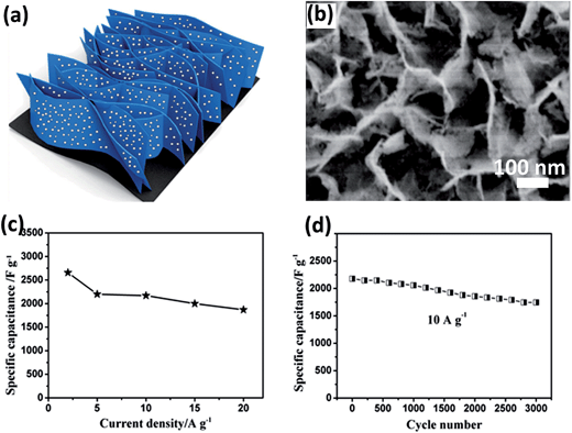 | ||
| Fig. 1 (a) Schematic illustration of ultrathin porous NiCo2O4 nanosheet arrays on flexible CF. (b) SEM image of NiCo2O4–CF composite. (c) Corresponding SCs at different current densities. (d) Cycling performance at a current density of 10 A g−1. Reproduced with permission from ref. 37. Copyright 2013, American Chemical Society. | ||
2.4 Template method
Mesostructured BTMO possesses attractive advantages, such as high surface areas, tunable pore sizes and morphologies. These features are important for electrochemical materials because the unique structure can promote the interface contact between electrode and electrolyte. Furthermore, the mesopores allow the liquid electrolyte to easily diffuse into the electrode materials. Thus, the mesoporous structure is very attractive in applications for catalysis, adsorption, sensors, supercapacitors, and lithium-ion batteries.40,41 However, the initial attempts of synthesizing mesoporous BTMO were not very successful because of thermal instability. With the development of new methods for the preparation of mesoporous BTMOs, the template method is widely used coupled with solvothermal/hydrothermal method for the synthesis of mesostructured BTMOs. Template-directed methods can be classified into two types, hard-template42,43 and soft-template methods.44,45 Among the hard templates, silica is one of the most frequently used templates due to its tetra-connected covalent bonds.46 Mesoporous silicas have highly ordered nanoscale structures and uniform pore size distributions. Therefore, they are ideal hard templates for mesostructured BTMO materials. For example, Yuan et al. synthesized ultrathin mesoporous hollow NiCo2O4 structures using silica spheres as a template.47 The as-prepared mesoporous hollow NiCo2O4 microspheres were uniform in size and structurally stable after the template removal, as shown in Fig. 2. As a potential pseudocapacitive electrode for ECs, the mesoporous hollow NiCo2O4 sub-microspheres exhibit high specific capacitance and remarkable long-term cycling stability at high current densities. Lu et al. reported a NiCo2O4 electrode with a highly ordered mesoporous structure and nanocrystalline walls using a hard-template method.48 Here, mesoporous silica KIT-6 templates are used as hard templates to fabricate mesoporous-structured NiCo2O4, then the silica template was removed by hot NaOH solution. This method provides an easy way to produce uniform mesoporous structured BTMOs. As shown in Fig. 2, a narrow pore size distribution, centered at ∼3.7 nm (Fig. 2d), was observed for the sample prepared with KIT-6 as template. Other mesoporous BTMOs, such as CoFe2O4 (ref. 49 and 50) and NiFe2O4,51,52 were also successfully prepared by the hard-template method with mesoporous silica or carbon as hard templates.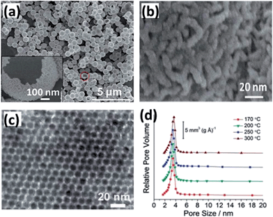 | ||
| Fig. 2 (a and b) SEM images with different magnifications for the hollow NiCo2O4 sub-microspheres. The inset in (a) is an enlargement of the part indicated by the circle. (c and d) PXRD pattern and pore size distribution of mesoporous NiCo2O4 prepared at different temperatures. Reprinted from ref. 47 and 48 with permission. Copyright 2012, The Royal Society of Chemistry. | ||
Soft-template method is also applied in the synthesis of BTMOs. Soft templates include surfactants, flexible organic molecules, microemulsions or block copolymers, which can act as structure-directing agents in the synthetic process. Compared to the hard-template method, the soft-template method has various advantages. Soft templates have different forms and they are easy to construct without complicated facilities. Moreover, they are inexpensive. Jan's group synthesized a nanocrystalline nickel molybdate (NiMoO4) 3D honeycomb thin-film electrode through a facile polymer template method.53 The novel material enhances lithium ion storage capabilities, and it is a promising material for energy storage. Zhang et al. synthesized mesoporous NiCo2O4 with PVP as capping agent. Serving as capping agent and coordinating to metal ions through –N and/or C![[double bond, length as m-dash]](https://www.rsc.org/images/entities/char_e001.gif) O functional groups of pyrrolidone ring, PVP plays an important role in the formation of mesoporous structures.54 It can help to direct the anisotropic growth and assemble particles into specific-structured NiCo2O4. In addition, the PVP adsorbed on the surface of NiCo2O4 can be removed during the annealing process with the release of gas, which is also useful for the formation of mesoporous structures.
O functional groups of pyrrolidone ring, PVP plays an important role in the formation of mesoporous structures.54 It can help to direct the anisotropic growth and assemble particles into specific-structured NiCo2O4. In addition, the PVP adsorbed on the surface of NiCo2O4 can be removed during the annealing process with the release of gas, which is also useful for the formation of mesoporous structures.
Both hard and soft templates provide a useful framework for controlling the synthesis of BTMOs with diverse morphologies. Coupled with the solvothermal/hydrothermal method or chemical bath deposition, it offers different opportunities for fundamental research.
2.5 Other synthetic methods
Apart from the abovementioned synthetic methods, there are other techniques that can be used for the synthesis of BTMOs and their composites, such as sol–gel technique and co-precipitation method.Generally, sol–gel technique attracts significant attention for the synthesis of BTMOs because it offers controllable purity, composition, homogeneity and temperature. It can be briefly summarized to be the transformation from the precursor solution to an inorganic solid. Although the merits of sol–gel technique are obvious compared with others, its application for large-scale synthesis is still hindered by the requirement of large amounts of organic solvents and reagents. Hu et al.60 reported the preparation of NiCo2O4 aerogels via sol–gel method. The obtained NiCo2O4 presents uniform morphology in the size distribution of 2–5 nm. It also shows good potential for supercapacitor electrodes with a high specific capacitance of 1400 F g−1 and good cycling stability. In the study by Yuan et al.,80 a three-dimensional (3D) hierarchical porous network-like NiCo2O4 framework was fabricated via polymer-assisted route. The 3D continuous framework offers a transport pathway for electrons to penetrate. It also presents a promising synthetic strategy for the fabrication of other binary complex metal oxides and/or ternary metal oxides with a controlled composition and porous structure.
Co-precipitation is another commonly used approach for the fabrication of BTMOs. Hierarchical porous nanoflakes, mesoporous and nanoneedle arrays of NiCo2O4 have been synthesized using this method.81,83,85 It provides a simple route for one-pot synthesis, and the reaction conditions are mild and simple.
All the abovementioned methods play different roles in the synthesis of BTMOs and their composites. For fundamental research into this specific area, the authors believe that more and more inspiring approaches will be developed.
3. BTMO based supercapacitor
Currently, the demand for energy supply is dramatically increasing. Several social problems have been caused by the hard reality, which compels us to search for effective routes to build high performance devices.55 One of the most environmentally friendly ways to deal with the severe problem is to exploit devices based on renewable energy sources, such as solar cells, lithium-ion batteries and supercapcitors. Facing these realities, researchers are engrossed in transition metal oxides as electrode materials for supercapacitor because of their outstanding electrochemical performance. However, compared to the single-component oxides, binary metal oxide could offer richer redox chemical ability and combine the contributions from two types of ions. For instance, through the substitution of Ni for Co in the spinel Co3O4 lattice, the electrochemical activity of NiCo2O4 could be significantly improved.56,57 Therefore, BTMOs and their composites have attracted wide interest in the applications of supercapacitors.3.1 Binary metal oxides
BTMOs with a variety of crystal structures, such as spinel, scheelite, and CaFe2O4-type, have been widely studied as materials for supercapacitors. BTMOs contain at least one transition metal ion and one or more electrochemically active/inactive ions. Depending on the structure, morphology, particle size, and metal ions, large and stable reversible capacities have been reported.| NiCo2O4 + OH− + H2O ↔ NiOOH + 2CoOOH + 2e− | (1) |
| CoOOH + OH− ↔ CoO2 + H2O + e− | (2) |
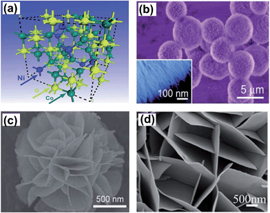 | ||
| Fig. 3 (a) Crystal structure of NiCo2O4 unit cell with the spinel structure. SEM images of (b) urchin-like, the inset shows ultrafine NiCo2O4 nanowires (c) flower-like (d) nanoflake array of NiCo2O4. Reprinted from ref. 63 with permission, Copyright 2012, The Royal Society of Chemistry; reprinted from ref. 69 with permission, Copyright 2013, American Chemical Society; reprinted from ref. 82 with permission, Copyright 2012, The Royal Society of Chemistry. | ||
In the former researches, NiCo2O4 powder was fabricated by several techniques, including ball milling,71 coprecipitation,61,72–74 KIT-6 template,48 hydrothermal,58,59,63,75 and sol–gel.76,60 Subsequently, the working electrode is prepared via the traditional slurry-coating technique for electrochemical measurement. Various morphologies have been developed for energy storage devices, such as flower-like,77–79 urchin-like,58,63 porous-like,80 nanowires,59,73 and nanoflakes80,146,148 (Fig. 3b–d). Different morphologies offer various EC performances.
For example, Wang et al. synthesized NiCo2O4 evolving from nanorods, straw bundles to urchin-like spheres via simple hydrothermal method without any templates.63 The NiCo2O4 achieves different morphologies with a change in urea amount, as shown in Fig. 4a–c. The as-obtained urchin structure presents uniform diameters of 5 μm with numerous nanorods (100–200 nm) grown from the center. The large specific surface area (99.3 m2 g−1) allows the electrons to easily penetrate into the electrolyte. Electrochemical measurement (Fig. 4d and e) indicates that the NiCo2O4 urchins exhibit a specific capacitance of 1650 and 1348 F g−1 at current densities of 1 and 15 A g−1, respectively. The degradation is 9.2% at a current density of 8 A g−1 after 2000 cycles, indicating an excellent cycling stability (Fig. 4f).
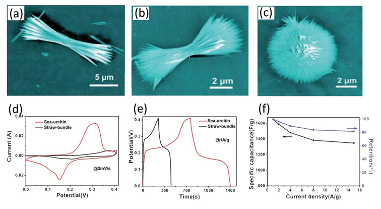 | ||
| Fig. 4 (a and c) SEM images of NiCo2O4 obtained by a hydrothermal process at different pH values. (d) Comparative CV curves recorded at a scan rate of 2 mV s−1 for two different electrodes. (e) Galvanostatic charge–discharge at a current density of 1 A g−1 for the two electrodes. (f) Variation of specific capacitance against current density. Reproduced with permission from ref. 63, Copyright 2012, Royal Society of Chemistry. | ||
Recently, a mesoporous Ni0.3Co2.7O4 hierarchical structure was synthesized via a facile precipitation method followed by a controlled annealing process by Lou et al.83 Here, aqueous solutions of Ni(NO3)2 and CoCl2 and ethanol (EtOH) were mixed at room temperature. Then, Na2C2O4 solution was quickly poured into the above solution. Subsequently, the pink precipitates were subjected to thermal annealing to form the mesoporous hierarchical structure, as shown in Fig. 5. By thorough investigation of the annealing temperature, it was found that the sample prepared at 400 °C possesses more abundant mesopores and exhibits a higher specific surface. A high specific capacitance of 960 and 805 F g−1 is obtained under the current densities of 0.625 and 6.25 A g−1, respectively, with excellent stability. The excellent electrochemical performance can be attributed to the desirable composition and the unique hierarchical mesoporous architectures.
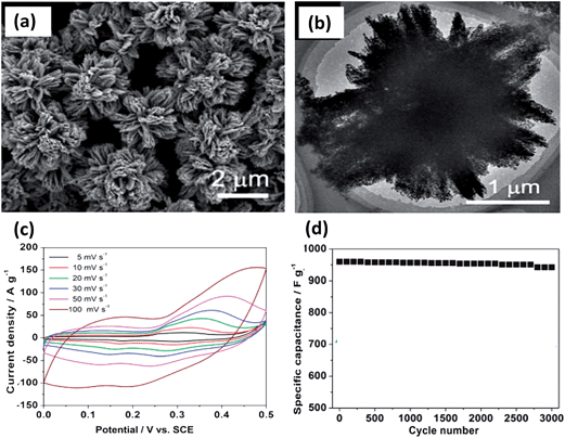 | ||
| Fig. 5 (a and b) SEM and TEM images. (c) Cyclic voltammetry measurements. (d) Stability performance of 400 °C post-annealing mesoporous Ni0.3Co2.7O4 hierarchical architectures. Reproduced with permission from ref. 83, Copyright 2013, Royal Society of Chemistry. | ||
As mentioned in the former part, generally an active material is coated on a current collector for electrochemical measurements, which contains a binder and a conductivity agent. It leads to an insufficient contact between the electroactive sites of the active material and electrolyte. Moreover, the binder will limit electrolyte penetration inside the active material and result in the electrons being unable to transport at a sufficiently fast rate for high rate capability. Therefore, it is necessary to grow electroactive nanostructures on conductive substrates to be directly used as binder-free electrodes for supercapacitors. Zhang and his coworkers successfully grew single-crystalline nanoneedle arrays of NiCo2O4 on Ni foam and Ti foil through a simple solution method along with a post-annealing treatment.85 It can be clearly seen from Fig. 6a and b that the needle-like NiCo2O4 are uniformly grown on the Ni substrate and form an array structure. Serving as binder-free supercapacitor electrodes, it exhibits high capacitance and the overall capacitance loss after 2000 cycles is calculated to be 10.6%. Liu et al. also synthesized a novel NiCo2O4@NiCo2O4 core–shell nanoflake array on Ni foam by hydrothermal method together with chemical bath deposition (CBD) and post-annealing process (Fig. 7a).69 As seen from Fig. 7b, the surface presents leaf-like ultrathin nanoflakes, which form a highly porous core–shell architecture. The nanoflake shells are interconnected and present innumerable holes, which is helpful for electron transport during the charge–discharge process and can significantly improve the electrochemical performance. NiCo2O4 nanosheet arrays were also deposited on flexible carbon fabric, which exhibited a high specific capacitance and superior cycling life (Fig. 7c). Wang et al. directly grew two different porous NiCo2O4 nanoarchitectures (nanowires and nanosheets) on carbon cloth (Fig. 7d and e). The pseudocapacitive difference is related to the surface area and pore structure of NiCo2O4.86 For example, a hierarchical NiCo2O4 nanowire array on Ni foam was synthesized via a simple hydrothermal process by Wang et al. (Fig. 7f and g).87 The as-fabricated supercapacitor presents an excellent electrochemical performance of 161 mF cm−2 at 1 mA cm−2. It also shows good stability over 3000 cycles with wonderful flexibility. Although directly growing active BTMOs on Ni foam presents many intriguing advantages, there are still certain drawbacks. The measured capacitance of the composite may contain part of the capacitance contributed by the oxidation of Ni foam.84 Moreover, the electrodes were hindered from practical usage by the high cost of Ni foam. The extra weight produced by Ni foam increases the mass loading for the active material.
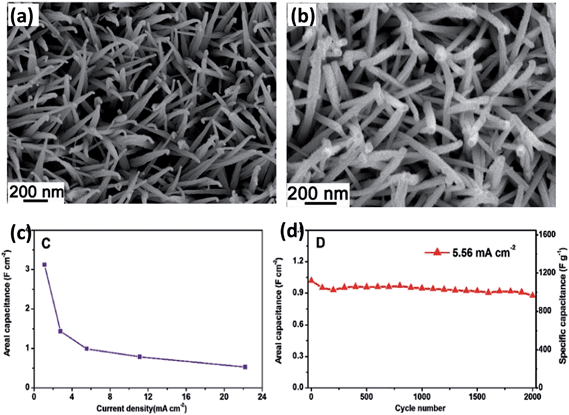 | ||
| Fig. 6 SEM images of crystallized NiCo2O4 nanoneedle arrays grown on (a) Ni foam and (b) Ti foil. (c) The areal capacitance as a function of current density. (d) The capacitance as a function of cycle number at 5.56 mA cm−2 of the NiCo2O4–Ni electrode. Reproduced with permission from ref. 85, Copyright 2012, Royal Society of Chemistry. | ||
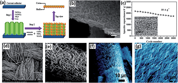 | ||
| Fig. 7 (a) Schematic of two-step synthesis of NiCo2O4@NiCo2O4 core–shell nanoflake arrays on Ni foam. (b) SEM image of NiCo2O4@NiCo2O4 core–shell nanoflake arrays obtained by chemical bath deposition. Reproduced with permission from ref. 69, Copyright 2013, American Chemical Society. (c) SEM image of NiCo2O4–CF composites and cycling performance at a current density of 10 A g−1. Reproduced with permission from ref. 37, Copyright 2012, American Chemical Society. (d and e) SEM images of the NiCo2O4 nanosheet grown on carbon cloth at different magnifications. (f and g) SEM images of NiCo2O4 nanowire arrays grown on Ni foams. Reproduced with permission from ref. 86, Copyright 2013, American Chemical Society. | ||
Table 2 lists the different methods used for synthesizing NiCo2O4 and their supercapacitor performances. By comparison in Table 2, it can be seen that NiCo2O4 with 3D structures exhibits better electrochemical performance than normal morphology. In addition, mesoporous-structured NiCo2O4 possesses relatively higher capacitances. These facts could be attributed to the porous structure and three-dimensional structure affording a continuous network and extra active sites for the redox reaction with charges. It also benefits the electron penetration in the electrolyte. It can be concluded that the synthetic conditions significantly influence the morphology and performance of the products.
| Morphology | Synthesis method | Specific capacitance | Current density | Reference |
|---|---|---|---|---|
| 3D dendritic films on stainless steel substrate | Electrodeposition | — | — | 36 |
| Nanosheet arrays on carbon fabric | Electrodeposition | 2658 F g−1 | 2 A g−1 | 37 |
| Hollow sub-microspheres | Hard template | 678 F g−1 | 1 A g−1 | 47 |
| Mesoporous | Hard template | 8.2 F cm−2 | 28.6 A g−1 | 48 |
| Urchin-like | Hydrothermal | 658 F g−1 | 1 A g−1 | 58 |
| Urchin-like | Hydrothermal | 1650 F g−1 | 1 A g−1 | 63 |
| Hierarchical core–shell nanoflake arrays on Ni foam | Hydrothermal and chemical deposition | 1.55 F cm−2 | 2 mA cm−2 | 69 |
| Hierarchical porous nanowires | Sol–gel | 743 F g−1 | 1 A g−1 | 74 |
| 3D hierarchical flower-shaped | Microwave-assisted heating reflux | 1006 F g−1 | 1 A g−1 | 79 |
| 3D hierarchical porous network-like framework | Sol–gel | 587 F g−1 | 2 A g−1 | 80 |
| Hierarchical porous nanoflakes | Precipitation method | 1270 F g−1 | 1 A g−1 | 81 |
| Mesoporous | Precipitation method | 960 F g−1 | 0.625 A g−1 | 83 |
| Nanoneedle arrays on Ni foam | Co-precipitation | 3.12 F cm−2 | 1.11 mA cm−2 | 85 |
| Nanowires on carbon cloth | Hydrothermal | 245 F g−1 | 1 A g−1 | 86 |
| Nanosheets on carbon cloth | Hydrothermal | 123 F g−1 | 1 A g−1 | 86 |
| Nanowire arrays on Ni foam | Hydrothermal | 161 mF cm−2 | 1 mA cm−2 | 87 |
| Chain-like nanowires | Hydrothermal | 1284 F g−1 | 2 A g−1 | 144 |
ZnCo2O4 is another type of spinel cobaltite, which has also been investigated in applications for supercapacitors. There are many methods for the synthesis of ZnCo2O4, such as molten salt, hydrothermal, urea combustion and electrospinning methods.88–91 It possesses the same structure as NiCo2O4 except Zn2+ replaces Co2+ at the tetrahedral site in Co3O4, which also can be utilized in electrochemical applications. For instance, Xie et al. synthesized microspheres of ZnCo2O4via a facile solution method.92 Liu et al. fabricated hierarchical ZnCo2O4 architectures on nickel foam via polyol refluxing (Fig. 8a).93 SEM images (Fig. 8b) show that the ZnCo2O4 nanorods completely deposited on the nickel foam with uniform diameters; they presented good capacitive behavior and excellent cycling stability (Fig. 8c and d).
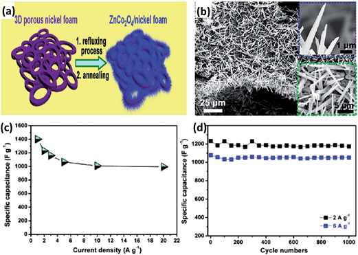 | ||
| Fig. 8 (a) Schematic of the synthesis of ZnCo2O4 nanorods/nickel foam. (b) SEM images of ZnCo2O4 nanorods grown on nickel foam. (c) Specific capacitance as a function of the current density of ZnCo2O4 nanorods. (d) Cycling performance of ZnCo2O4 nanorods/nickel foam electrodes at various current densities. Reproduced with permission from ref. 93, Copyright 2013, American Chemical Society. | ||
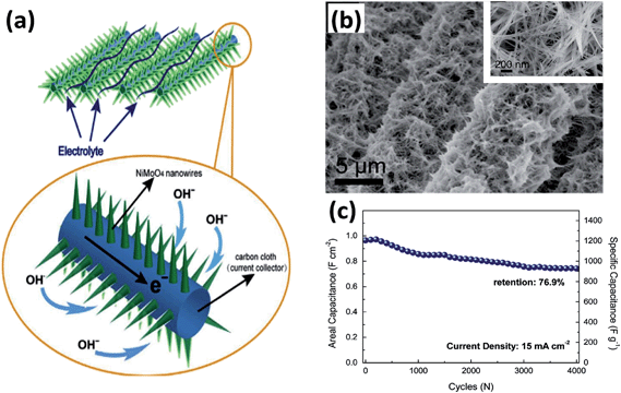 | ||
| Fig. 9 (a) Schematic of the application advantages of NiMoO4 nanowires on carbon cloth. (b) Low- and high-magnification images of NiMoO4 nanowires on carbon cloth. (c) Cycling performance of NiMoO4 nanowires grown on carbon cloth. Reproduced with permission from ref. 107, Copyright 2014, Elsevier B.V. | ||
Recently, the development of molybdenum- and cobalt-based binary oxides with unique structure and properties has attracted significant interest. For example, CoMoO4·0.9H2O nanorods have been successfully fabricated via hydrothermal method by Liu et al. (Fig. 10a).108 As known, the Faradaic reactions corresponding to the redox of CoMoO4 can be demonstrated as follows:109
| 3[Co(OH)3] = Co3O4 + 4H2O + OH− + 2e− | (3) |
| Co3O4 + H2O + OH− = 3CoOOH + e− | (4) |
| CoOOH + OH− = CoO2 + H2O + e− | (5) |
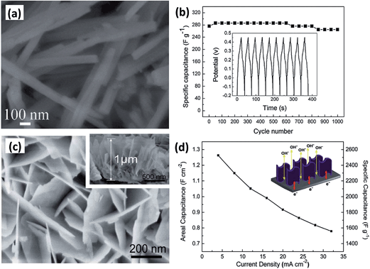 | ||
| Fig. 10 (a) SEM image of CoMoO4·0.9H2O nanorods. (b) Cycling performance of the as-fabricated CoMoO4·0.9H2O. (c) SEM image of CoMoO4 NPAs on nickel foam. The inset is CoMoO4 NPAs from a side view. (d) ASC of CoMoO4 NPAs at various discharge current densities. The inset is the schematic of the application advantages of CoMoO4 NPAs on Ni foam. Reproduced with permission from ref. 110, Copyright 2010, Royal Society of Chemistry. | ||
Because of the rich redox reactions provided by CoMoO4, it offers a good capacitive behavior of 326 F g−1 (current density of 5 mA cm−2) and 96% of the initial specific capacitance remained after 1000 cycles, as shown in Fig. 10b. CoMoO4 nanoplate arrays (NPAs) were also deposited on Ni foam via a template-free hydrothermal route by Guo et al.110 The height of the CoMoO4 nanosheet arrays is about 1 μm with an opened-up network. Serving to be a supercapacitor electrode, it exhibited remarkable electrochemical performance with a high specific capacitance and excellent cycling stability (Fig. 10c and d).
Among ferrites, MnFe2O4 exhibits larger capacitance than other components owing to the electron transfer of Mn ions at the tetrahedral sites, while other ferrites cannot.114 The Studies on Mn-based BTMOs in supercapacitors also have been reported. The spinel NiMn2O4 has the advantages of good conductivity, good stability and relatively high capacity compared to Mn and Ni mixed oxides.115 For example, Liu et al. synthesized NiMn2O4 aerogel via sol–gel process.121 The pore size of NiMn2O4 was around 8–10 nm with a specific area of 201 m2 g−1, which presents a capacitance of 243 F g−1 at 5 mV s−1. The stability of the sample was 96% of the initial specific capacitance even after 5000 cycles at 20 mV s−1. It is predictable that the studies on other BTMOs still can be significantly carried out, but there is no doubt that there will be more interesting findings.
3.2 Binary metal oxide–carbon composites
Although BTMOs possess extremely attractive theoretical capacitance based on the redox reaction, they still suffer from inferior rate performance, low utilization rate and poor cycling stability. Recently, carbon-based materials are widely utilized as negative electrodes in asymmetric electrochemical capacitors because of their high surface area, high conductivity and stable chemical property. They are usually incorporated into pseudocapacitive BTMOs to enhance their conductivity and further improve the power density.116–118 Therefore, the construction of BTMOs–carbon composites is highly preferred.Graphene, a single-atom-thick monolayer of sp2 carbon atoms perfectly arranged in a honeycomb lattice, is an attractive material with extraordinary structural, electrical, optical, and mechanical properties.119–124 In particular, it exhibits a large specific surface area and high mobility, which facilitates electron transfer during the charging–discharging process. The combination of BTMOs with graphene can offer many merits. For example, Carriazo et al. fabricated NiCo2O4 nanowires–graphene oxide composites using microwave irradiation and a mild heating method (Fig. 11a). The obtained composite exhibits the advantages of both NiCo2O4 and graphene. It shows a high specific capacitance of nearly 735 F g−1 at current densities of up to 33 A g−1.125 In addition, other NiCo2O4–graphene composites with good electrochemical performance have also been synthesized by different groups.61,125–127 Nethravathi et al. obtained a porous NiCo2O4 hexagonal ring–graphene hybrid (Fig. 11c) through a similar process starting from β-Ni0.33Co0.67(OH)2 platelets (Fig. 11b). As an electrode material, this material exhibits a large capacity, high rate capability, and excellent cycling stability (Fig. 11d and e). Ghosh et al. also reported a novel hydrothermal procedure to synthesize a hexahedron-shaped α-MnMoO4–graphene hybrid using various weight percentages of graphene.128 The composite exhibited a highest specific capacitance of 455 F g−1 at a constant current density of 2.5 A g−1. NiMoO4 has also been hybridized with graphene and the composite exhibits good performance as well. They also investigated a cost-effective hydrothermal procedure to hybridize one-dimensional NiMoO4·nH2O nanorods with graphene.129 Here, the 1D NiMoO4·nH2O nanorods were randomly distributed on the graphene surface, as shown in Fig. 11f. Owing to the high surface area, high porosity and conductivity, the composite has increased conductivity, lower charge transfer resistance and diffusion resistance than bare NiMoO4, and the charge transfer process was facilitated.
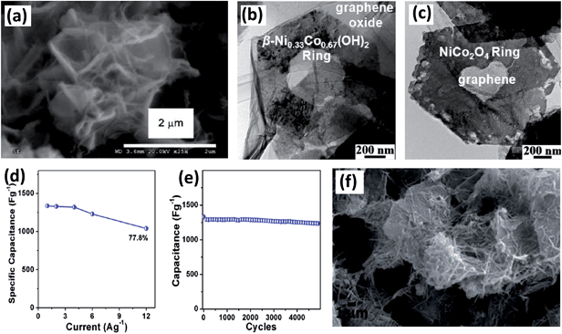 | ||
| Fig. 11 (a) SEM image of NiCo2O4–graphene oxide nanocomposites. Reproduced with permission from ref. 125, Copyright 2013, Royal Society of Chemistry. HRTEM images of (b) β-Ni0.33Co0.67(OH)2-hexagonal ring–graphene oxide and (c) NiCo2O4 hexagonal ring–graphene hybrid. (d) Specific capacitance at various current densities. (e) Cycling performance of NiCo2O4 hexagonal ring–graphene hybrid. Reproduced with permission from ref. 127, Copyright 2014, American Chemical Society. (f) SEM image of NiMoO4·nH2O nanorods–graphene composite. Reproduced with permission from ref. 129, Copyright 2013, Royal Society of Chemistry. | ||
Recently, reduced graphite oxide–NiFe2O4 (RGO–NiFe2O4) composites were synthesized at room temperature, as shown in Fig. 12a.130 From the TEM image, it can be seen that NiFe2O4 was homogeneously distributed on the RGO surfaces (Fig. 12b). The electrochemical properties were studied on a three-electrode electrochemical station using 1 M Na2SO4 aqueous solution as electrolyte (Fig. 12c and d). The specific capacitances at a current density of 1 A g−1 of products prepared under different conditions can be calculated according to the GCD curves in Fig. 12c. It can be concluded that the innovative combination of nickel ferrite and rGO still provide promising applications in supercapacitors.
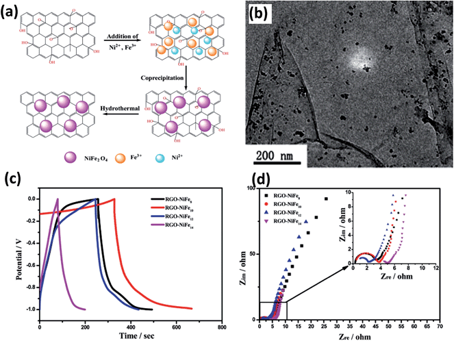 | ||
| Fig. 12 (a) Schematic of the preparation of the RGO–NiFe2O4 composite. (b) TEM image of RGO–NiFe8. (c) Charge–discharge behaviors of RGO–NiFen composites at a current density of 1 A g−1. (d) EIS plots of RGO–NiFe composites at room temperature. Reproduced with permission from ref. 130, Copyright 2013, Royal Society of Chemistry. | ||
Compared to the binary metal oxides, better electrochemical cycling stabilities are reported for carbonaceous material and BTMOs, such as CoSnO3@C nanoboxes,131 ZnFe2O4–C hollow spheres,132 NiCo2O4–C nanocomposites,133 and MWCNT–ZnFe2O4 nanocomposites.134 This phenomenon arises from the fact that the conductive carbon can serve to be a physical buffering matrix, which can prevent interparticle agglomeration and enhance their electronic conductivity. Recently, an interesting work on super-long-life supercapacitors based on nanohoneycomb-like strongly coupled CoMoO4–3D graphene hybrid electrodes was reported by Yu et al.135 Three-dimensional (3D) graphene has continuously interconnected macroporous structures, with large surface area, low mass density, and high electrical conductivity.136–138 In particular, the 3D porous structure is ideal to serve as a scaffold for the fabrication of monolithic composite and hybrid electrodes. Because there are many reports about synthesizing 3D graphene–TMOs composites as supercapacitors,138–140 significant efforts have been made with BTMOs. Yu et al. presented a simple hydrothermal strategy for the growth of CoMoO4 strongly coupled on 3D graphene foam (Fig. 13a).135 As shown in Fig. 13b, the depth of the CoMoO4 was about 500 nm. The porous structure provided a stable structure and very large surface area for the ionic transportation and oxidation/redox reactions. Owing to the high dispersion of CoMoO4 within the amorphous carbon matrix and an efficient interfacial affinity between the two components, the hybrid material displays outstanding electrochemical activity with an initial specific capacitance as high as 2741 and 1101 F g−1 at current densities of 1.43 and 85.71 A g−1, respectively, as shown in Fig. 13c. More interestingly, it can retain 96.36% of its initial specific capacitance with a current density of 400 A g−1 even after 100![[thin space (1/6-em)]](https://www.rsc.org/images/entities/char_2009.gif) 000 cycles at room temperature (Fig. 13d). The superior stability can be attributed to the following reasons: (1) the superior electrical conductivity provides excellent conductivity for electrons to penetrate during the charge–discharge process and improves the performance in specific capacitance. (2) The large specific area provided in the composites makes the charge transportation to occur easily. (3) The excellent mechanical strength and flexibility makes the electrode stable. (4) The defects of 3D graphene will significantly affect the molecule adsorptions during the hydrothermal process of CoMoO4 growth.
000 cycles at room temperature (Fig. 13d). The superior stability can be attributed to the following reasons: (1) the superior electrical conductivity provides excellent conductivity for electrons to penetrate during the charge–discharge process and improves the performance in specific capacitance. (2) The large specific area provided in the composites makes the charge transportation to occur easily. (3) The excellent mechanical strength and flexibility makes the electrode stable. (4) The defects of 3D graphene will significantly affect the molecule adsorptions during the hydrothermal process of CoMoO4 growth.
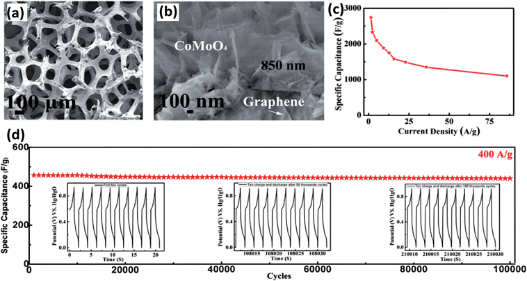 | ||
| Fig. 13 (a and b) SEM images of strongly coupled CoMoO4–3D graphene hybrid at various magnifications. (c) Specific capacitance as a function of current density. (d) Cycling performance of honeycomb-like CoMoO4–3D graphene hybrid electrode. Reproduced with permission from ref. 135, Copyright 2013, WILEY-VCH Verlag GmbH & Co. KGaA, Weinheim. | ||
The above examples clearly demonstrate the synergistic effect of BTMOs and carbon materials. It should be noted that NiCo2O4 is a p-type semiconductor with a band gap of 2.1 eV, which shows no superiority compared with conductors. Thus, using carbonaceous materials with good electrical conductivity to combine with BTMOs is a potential method to promote the capacitance performance. Furthermore, carbon materials have a high specific area, which can provide electron transportation channels and produce significant effects.
3.3 Binary metal oxide–metal oxide composites
It is known that in addition to a mesoporous structure, the electrical conductivity and the degree of crystallinity are other key factors that affect the electrochemical performance of oxide-based electrode materials. Because the conductivity of electrode materials plays a critical role in charge-transfer reactions and internal resistance of the electrodes, it can be enhanced by doping with other semiconductors to introduce impurity band effects. Therefore, because many BTMOs and TMOs are p-type semiconductors, many studies of combining BTMOs with TMOs have been done and a series of good results were achieved. For instance, Lou et al. fabricated hierarchical NiCo2O4@MnO2 core–shell heterostructured nanowire arrays on nickel foam, which presented an aerial specific capacitance of 3.31 F cm−2 at 2 mA cm−2 (Fig. 14a).141 Hierarchical NiCo2O4@NiO core–shell arrays on carbon cloth were fabricated using a chemical bath deposition (CBD) process followed by a thermal treatment.147 Because of the synergetic effect of the different components, a high gravimetric capacitance of 1792 F g−1 at 5 mA cm−2 is achieved. A NiO–NiCo2O4–Co3O4 composite had also been synthesized via a sol–gel process by Kang et al., as shown in Fig. 14b. The fabricated composite exhibits high specific capacitance (1717 F g−1) and excellent electrochemical stability (94.9% retention after 1000 cycles) due to the synergistic effect of NiO, NiCo2O4, and Co3O4 (Fig. 14c).142 Furthermore, MnMoO4–CoMoO4 heterostructured nanowires were fabricated, which exhibit higher performance than single MnMoO4 and CoMoO4 nanowires.109 3D Co3O4@MMoO4 (M = Ni, Co) composites were fabricated on Ni foam by Mai et al. via a hydrothermal method.109 SEM image showed that the Co3O4 “branches” are tightly bonded and totally covered with the “leaves” of nanoflakes and the space between Co3O4 arrays is abundantly utilized, which increased the energy and power density of materials (Fig. 14d).143 From the above reports, it can be seen that the combination of two types of materials not only provides the composite material with stronger redox ability, but also enhances the structural stability. Most importantly, the higher conductivity of BTMOs can serve as a backbone to support and provide effective electrical connection to active electrode materials, which can produce a synergistic effect of all individual constituents. For these reasons, tuning the microstructure, crystallinity, and electrical conductivity of oxide-based materials are significantly essential in supercapacitors.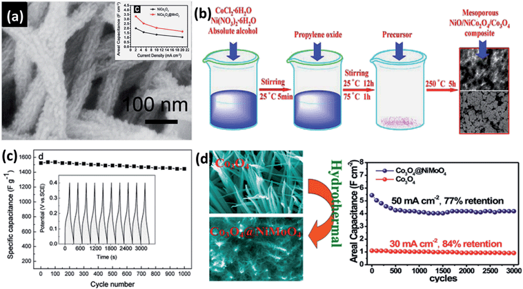 | ||
| Fig. 14 (a) SEM image of NiCo2O4@MnO2 core–shell heterostructured nanowire arrays on nickel foam. The inset shows the performance of the NiCo2O4 and NiCo2O4@MnO2. (b) Synthesis procedure for mesoporous NiO–NiCo2O4–Co3O4 composite. (c) Cycling performance of the as-fabricated composite (the inset is the first ten charge–discharge curves of NiO–NiCo2O4–Co3O4). (d) SEM images of Co3O4@NiMoO4 core–shell NWAs on Ni foam and its long-term cycling stability. Reproduced with permission from ref. 143, Copyright 2014, Elsevier B.V. | ||
4. Outlook
In this review, we have systematically outlined the conventional strategies and recent progress related to binary metal oxides as energy storage materials in supercapacitors. As is known, with regard to the evaluation of electrode materials in supercapacitors, the conductivity and specific surface area are two critical factors that determine the supercapacitor performance. In addition to the designation of special structured BTMOs, many strategies are adopted for synthesizing composite electrodes. Because BTMOs are p-type semiconductors, whose electric conductivity is significantly low to support fast electron transport required for high rates, the combination of nanostructured carbons, such as CNTs, graphene and mesoporous carbons becomes a useful approach for BTMO-based composite electrodes. The composite exploits the benefits of both the pseudocapacitive nature of the metal oxide and conductive EDLC nature of the carbonaceous material, implying an efficient application potential for supercapacitors. Other studies have been also employed to fabricate BTMO materials with a high specific area. The doping of other TMOs can also introduce impurity band effects and can enhance the performance.Although significant progress has been made in energy storage for BTMOs in supercapacitors, there are still practical challenges and obstacles to overcome in the near future. Synthetically, there are still numerous difficulties to fabricate BTMOs that satisfy all the requirements of specific applications via a simple method. The authors believe that to fully exploit the potential of BTMO-based electrode materials, it is crucial for the researchers to optimize both the synthesis parameters and material properties. In addition, high specific capacitance and long cycling stability still remain a challenge to improve the electrochemical performance of BTMOs. Moreover, significant studies are required. However, we look forward to promoting further developments in this interesting area of research for achieving considerable progress in the future in supercapacitor applications.
Acknowledgements
The project was supported by Jiangsu Provincial Funds for Distinguished Young Scholars (BK20130046), the NNSF of China (21275076, 61328401), Program for New Century Excellent Talents in University (NCET-13-0853), Qing Lan Project, Research Fund for the Doctoral Program of Higher Education of China (20123223110008), Synergetic Innovation Center for Organic Electronics and Information Displays, and the Priority Academic Program Development of Jiangsu Higher Education Institutions (PAPD).References
- Z. B. Lei, N. Christov and X. S. Zhao, Energy Environ. Sci., 2011, 4, 1866 CAS.
- Z. Chen, Y. C. Qin, D. Weng, Q. F. Xiao, Y. T. Peng, X. L. Wang, H. X. Li, F. Wei and Y. F. Lu, Adv. Funct. Mater., 2009, 19, 3420 CrossRef CAS.
- J. F. Xie, X. Sun, N. Zhang, K. Xu, M. Zhou and Y. Xie, Nano Energy, 2013, 2, 65 CrossRef CAS PubMed.
- T. C. Liu, W. G. Pell and B. E. Conway, Electrochim. Acta, 1997, 42, 3541 CrossRef CAS.
- X. C. Dong, Y. F. Cao, J. Wang, M. B. Chan-Park, L. H. Wang, W. Huang and P. Chen, RSC Adv., 2012, 12, 4364 RSC.
- J. X. Zhu, W. H. Shi, N. Xiao, X. H. Rui, H. T. Tan, X. H. Lu, H. H. Hng, J. Ma and Q. Y. Yan, ACS Appl. Mater. Interfaces, 2012, 4, 2769 CAS.
- D. Sarkar, G. G. Khan, A. K. Singh and K. Manda, J. Phys. Chem. C, 2013, 117, 15523 CAS.
- Q. T. Qu, S. B. Yang and X. L. Feng, Adv. Mater., 2011, 46, 5574 CrossRef PubMed.
- J. Y. Zhu and J. H. He, ACS Appl. Mater. Interfaces, 2012, 4, 1770 CAS.
- M. V. Reddy, G. V. Subba Rao and B. V. R. Chowdari, Chem. Rev., 2013, 113, 5364 CrossRef CAS PubMed.
- J. Liu and D. Xue, Adv. Mater., 2008, 20, 2622 CrossRef CAS.
- A. Cabenas, J. A. Darr, E. Lester and M. Poliakoff, J. Mater. Chem., 2001, 11, 561 RSC.
- K. Byrappa and M. Yoshimura, Handbook of Hydrothermal Technology, William Andrew Publishing, New York, 2001 Search PubMed.
- G. Pang, S. Feng, Z. Gao, Y. Xu, C. Zhao and R. Xu, J. Solid State Chem., 1997, 128, 313 CrossRef CAS.
- P. Petchpradab, T. Yoshida, T. Charinpanitkul and Y. Matsumura, Ind. Eng. Chem. Res., 2009, 48, 4587 CrossRef CAS.
- Y. Hakuta, H. Ura, H. Hayashi and K. Arai, Ind. Eng. Chem. Res., 2005, 44, 840 CrossRef CAS.
- K. Chen and D. Xue, CrystEngComm, 2012, 14, 8068 RSC.
- J. Wu and D. Xue, CrystEngComm, 2011, 13, 3773 RSC.
- R. Gedye, F. Smith, K. Westaway, H. Ali, L. Baldisera, L. Laberge and J. Rousell, Tetrahedron Lett., 1986, 27, 279 CrossRef CAS.
- R. J. Giguere, T. L. Bray, S. M. Duncan and G. Majetich, Tetrahedron Lett., 1986, 27, 4945 CrossRef CAS.
- I. Bilecka and M. Niederberger, Nanoscale, 2010, 27, 1358 RSC.
- S. Komarneni, M. C. D'Arrigo, C. Leonelli, G. C. Pellacani and H. Katsuki, J. Am. Ceram. Soc., 1998, 81, 304 Search PubMed.
- W. W. Wang, Mater. Chem. Phys., 2008, 108, 227 CrossRef CAS PubMed.
- S. W. Cao, Y. J. Zhu, G. F. Cheng and Y. H. Huang, J. Hazard. Mater., 2009, 171, 431 CrossRef CAS PubMed.
- X. Gu, W. M. Zhu, C. J. Jia, R. Zhao, W. Schmidt and Y. Q. Wang, Chem. Commun., 2011, 47, 5337 RSC.
- K. H. Chang, Y. F. Lee, C. C. Hu, C. I. Chang, C. L. Liu and Y. L. Yang, Chem. Commun., 2010, 46, 7957 RSC.
- V. V. Namboodiri and R. S. Varma, Green Chem., 2001, 3, 3146 RSC.
- S. Komarneni, Curr. Sci., 2003, 85, 1730 CAS.
- B. Y. Yu and S. Y. Kwak, Dalton Trans., 2011, 9989 RSC.
- C. O. Kappe, Angew. Chem., Int. Ed., 2004, 43, 6250 CrossRef CAS PubMed.
- L. Li, Z. Guo, A. Du and H. Liu, J. Mater. Chem., 2012, 22, 3600 RSC.
- S. Komarneni, R. Roy and Q. H. Li, Mater. Res. Bull., 1992, 27, 1393 CrossRef CAS.
- S. Komarneni, Q. Li, K. M. Stefansson and R. Roy, J. Mater. Res., 1993, 8, 176 Search PubMed.
- S. Komarneni, M. C. D'Arrigo, C. Leonelli, G. C. Pellacani and H. Katsuki, J. Am. Ceram. Soc., 1998, 81, 3041 CrossRef CAS PubMed.
- P. Taheri, S. Hsieh and M. Bahrami, J. Power Sources, 2011, 196, 6525 CrossRef CAS PubMed.
- R. P. Silva, S. Eugé nio, T. M. Silva, M. J. Carmezim and M. F. Montemor, J. Phys. Chem. C, 2012, 116, 22425 CAS.
- J. Du, G. Zhou, H. M. Zhang, C. Cheng, J. M. Ma, W. F. Wei, L. B. Chen and T. H. Wang, ACS Appl. Mater. Interfaces, 2013, 5, 7405 CAS.
- L. Huang, D. Chen, Y. Ding, Z. L. Wang, Z. Zeng and M. Liu, ACS Appl. Mater. Interfaces, 2013, 5, 11159 CAS.
- G. Zhang, T. Wang, X. Yu, H. Zhang, H. Duan and B. Lu, Nano Energy, 2013, 2, 586 CrossRef CAS PubMed.
- F. Schüth, Angew. Chem., Int. Ed., 2003, 42, 3604 CrossRef PubMed.
- A. Taguchi and F. Schüth, Microporous Mesoporous Mater., 2005, 77, 1 CrossRef CAS PubMed.
- A. H. Lu and F. Schuth, Adv. Mater., 2006, 18, 1793 CrossRef CAS.
- A. Rumplecker, F. Kleitz, E. L. Salabas and F. Schuth, Chem. Mater., 2007, 19, 485 CrossRef CAS.
- P. Yang, D. Zhao, D. I. Margolese, B. F. Chmelka and G. D. Stucky, Chem. Mater., 1999, 11, 2813 CrossRef CAS.
- J. Fan, S. W. Boettcher and G. D. Stucky, Chem. Mater., 2006, 18, 6391 CrossRef CAS.
- D. Gu and F. Schüth, Chem. Soc. Rev., 2014, 43, 313 RSC.
- C. Z. Yuan, J. Y. Li, L. R. Hou, J. D. Lin, G. Pang, L. H. Zhang, L. Lian and X. G. Zhang, RSC Adv., 2013, 3, 18573 RSC.
- Q. Lu, Y. P. Chen, W. F. Li, J. G. Chen, J. Q. Xiao and F. Jiao, J. Mater. Chem. A, 2013, 1, 2331 CAS.
- B. Q. Liu, Q. F. Li, B. Zhang, Y. L. Cui, H. F. Chen, G. N. Chen and D. P. Tang, Nanoscale, 2011, 3, 2220 RSC.
- X. Yan, J. Chen, Q. Xue and P. Miele, Microporous Mesoporous Mater., 2010, 135, 137 CrossRef CAS PubMed.
- B. Li, M. Li, C. H. Yao, Y. F. Shi, D. R. Ye, J. Wu and D. Y. Zha, J. Mater. Chem. A, 2013, 1, 6742 CAS.
- H. Yen, Y. B. Seo, R. Guillet-Nicolas, S. Kaliaguine and F. Kleitz, Chem. Commun., 2011, 47, 10473 RSC.
- J. Haetge, I. Djerdj and T. Brezesinski, Chem. Commun., 2012, 48, 6726 RSC.
- Y. F. Zhang, M. Z. Ma, J. Yang, H. Q. Su, W. Huang and X. C. Dong, Nanoscale, 2013, 6, 4303 RSC.
- D. Pant, A. Singh, G. Van Bogaert, S. Irving Olsen, P. Singh Nigam, L. Diels and K. Vanbroekhoven, RSC Adv., 2012, 2, 1248 RSC.
- L. Huang, D. C. Chen, Y. Ding, S. Feng, Z. L. Wang and M. L. Liu, Nano Lett., 2013, 13, 3135 CrossRef CAS PubMed.
- X. Y. Yu, X. Z. Yao, T. Luo, Y. Jia, J. H. Liu and X. J. Huang, ACS Appl. Mater. Interfaces, 2013, 6, 3689 Search PubMed.
- J. W. Xiao and S. H. Yang, RSC Adv., 2011, 1, 588 RSC.
- H. L. Wang, Q. M. Gao and L. Jiang, Small, 2011, 7, 2454 CAS.
- T. Y. Wei, C. H. Chen, H. C. Chien, S. Y. Lu and C. C. Hu, Adv. Mater., 2010, 22, 347 CrossRef CAS PubMed.
- H. X. Wang, Z. A. Hu, Y. Q. Chang, Y. L. Chen, H. Y. Wu, Z. Y. Zhang and Y. Y. Yang, J. Mater. Chem., 2011, 21, 10504 RSC.
- Y. Sharma, N. Sharma, G. V. Subba Rao and B. V. R. Chowdari, Adv. Funct. Mater., 2007, 17, 2855 CrossRef CAS.
- Q. Wang, B. Liu, X. Wang, S. Ran, L. Wang, D. Chen and G. Shen, J. Mater. Chem., 2012, 22, 21647 RSC.
- J. Zhu and Q. Gao, Microporous Mesoporous Mater., 2009, 124, 144 CrossRef CAS PubMed.
- J. Chang, J. Sun, C. H. Xu, H. Xu and L. Gao, Nanoscale, 2012, 4, 6786 RSC.
- M. Lenglet, R. Guillamet, J. Dürr, D. Gryffroy and R. E. Vandenberghe, Solid State Commun., 1990, 74, 1035 CrossRef CAS.
- P. D. Battle, A. K. Cheetham and J. B. Goodenough, Mater. Res. Bull., 1979, 14, 1013 CrossRef CAS.
- Q. F. Wang, B. Liu, X. F. Wang, S. H. Ran, L. M. Wang, D. Chen and G. Z. Shen, J. Mater. Chem., 2012, 22, 21647 RSC.
- X. Y. Liu, S. J. Shi, Q. Q. Xiong, L. Li, Y. J. Zhang, H. Tang, C. D. Gu, X. L. Wang and J. P. Tu, ACS Appl. Mater. Interfaces, 2013, 5, 8790 CAS.
- X. Wang, X. D. Han, M. F. Lim, N. Singh, C. L. Gan, J. Ma and P. S. Lee, J. Phys. Chem. C, 2012, 116, 12448 CAS.
- R. Ding, L. Qi and H. J. Wang, Solid State Electrochem., 2012, 16, 3621 CrossRef CAS PubMed.
- S. K. Chang, K. T. Lee, Z. Zainal, K. B. Tan, N. A. Yusof, W. M. D. W. Yusoff, J. F. Lee and N. L. Wu, Electrochim. Acta, 2012, 67, 67 CrossRef CAS PubMed.
- C. Yuan, J. Li, L. Hou, L. Yang, L. Shen and X. Zhang, J. Mater. Chem., 2012, 22, 16084 RSC.
- H. Jiang, J. Ma and C. Li, Chem. Commun., 2012, 48, 4465 RSC.
- T. Wu, J. Li, L. Hou, L. C. Yuan, L. Yang and X. Zhang, Electrochim. Acta, 2012, 81, 172 CrossRef CAS PubMed.
- H. C. Chien, W. Y. Cheng, Y. H. Wang and S. Y. Lu, Adv. Funct. Mater., 2012, 22, 5038 CrossRef CAS.
- Z. Q. Liu, K. Xiao, Q. Z. Xu, N. Li, Y. Z. Su, H. J. Wang and S. Chen, RSC Adv., 2012, 3, 4372 RSC.
- C. H. An, Y. J. Wang, Y. N. Huang, Y. N. Xu, C. C. Xu, L. F. Jiao and H. T. Yuan, CrystEngComm, 2014, 16, 385 RSC.
- Y. Lei, J. Li, Y. Y. Wang, L. Gu, Y. F. Chang, H. Y. Yuan and D. Xiao, ACS Appl. Mater. Interfaces, 2014, 6, 1773 CAS.
- C. Z. Yuan, J. Y. Li, L. R. Hou, J. D. Lin, X. G. Zhang and S. L. Xiong, J. Mater. Chem. A, 2013, 1, 11145 CAS.
- I. Shakir, M. Sarfraz, U. Ali Rana, M. Nadeem and M. A. Al-Shaikh, RSC Adv., 2013, 3, 21386 RSC.
- L. L. Li, Y. L. Cheah, Y. Ko, P. Teh, G. Wee, C. L. Wong, S. J. Peng and M. Srinivasan, J. Mater. Chem. A, 2013, 1, 10935 CAS.
- H. B. Wu, H. Pang and X. W. (David) Lou, Energy Environ. Sci., 2013, 6, 3619 CAS.
- W. Xing, S. Z. Qiao, X. Z. Wu, X. L. Gao, J. Zhou, S. P. Zhuo, S. B. Hartono and D. Hulicova-Jurcakova, J. Power Sources, 2011, 196, 4123 CrossRef CAS PubMed.
- G. Q. Zhang, H. B. Wu, H. E. Hoster, M. B. Chan-Park and X. W. (David) Lou, Energy Environ. Sci., 2012, 5, 9453 CAS.
- H. W. Wang and X. F. Wang, ACS Appl. Mater. Interfaces, 2013, 5, 6255 CAS.
- Q. F. Wang, X. F. Wang, B. Liu, G. Yu, X. J. Hou, D. Chen and G. Z. Shen, J. Mater. Chem. A, 2013, 1, 2468 CAS.
- Y. Sharma, N. Sharma, G. V. Subba Rao and B. V. R. Chowdari, Chem. Mater., 2008, 20, 6829 CrossRef CAS.
- M. V. Reddy, K. Y. H. Kenrick, Y. W. Tang, G. Y. Chong, G. H. Leong and B. V. R. Chowdari, J. Electrochem. Soc., 2011, 158, 1423 CrossRef PubMed.
- B. Liu, J. Zhang, X. F. Wang, G. Chen, D. Chen, C. W. Zhou and G. Z. Shen, Nano Lett., 2012, 12, 3005 CrossRef CAS PubMed.
- W. Luo, X. L. Hu, Y. M. Sun and Y. H. Huang, J. Mater. Chem., 2012, 22, 8916 RSC.
- Q. S. Xie, F. Li, H. Z. Guo, L. S. Wang, Y. Z. Chen, G. H. Yue and D. L. Peng, ACS Appl. Mater. Interfaces, 2013, 5, 5508 CAS.
- B. Liu, B. Y. Liu, Q. F. Wang, X. F. Wang, Q. Y. Xiang, D. Chen and G. Z. Shen, ACS Appl. Mater. Interfaces, 2013, 5, 10011 CAS.
- W. Xiao, J. S. Chen, C. M. Li, R. Xu and X. W. Lou, Chem. Mater., 2010, 22, 746 CrossRef CAS.
- H. Ehrenberg, B. Schwarz and H. Weitzel, J. Magn. Magn. Mater., 2006, 305, 57 CrossRef CAS PubMed.
- B. Liu, S. H. Yu, L. J. Li, Q. Zhang and K. Jiang, Angew. Chem., Int. Ed., 2004, 43, 4745 CrossRef CAS PubMed.
- A. Maione and M. Devilers, J. Solid State Chem., 2004, 177, 2339 CrossRef CAS PubMed.
- C. Mazzocchia, C. Aboumrad, C. Diagne, E. Tempesti, J. M. Herrmann and G. Thomas, Catal. Lett., 1991, 10, 181 CrossRef CAS.
- U. Làenejavc, B. M. Jovíc, Z. Bašèarević, V. M. Maksimovíc and V. D. Jovíc, Electrochim. Acta, 2009, 54, 3115 CrossRef PubMed.
- K. Sieber, R. Kershaw, K. Dwight and A. Wold, Inorg. Chem., 1983, 22, 2667 CrossRef CAS.
- B. Senthilkumar, K. V. Sankar, R. K. Selvan and M. D. M. Manickam, RSC Adv., 2013, 3, 352 RSC.
- D. P. Cai, B. Liu, D. D. Wang, Y. Liu, L. L. Wang, H. Li, Y. R. Wang, C. X Wang, Q. H. Li and T. H. Wang, Electrochim. Acta, 2014, 115, 358 CrossRef CAS PubMed.
- H. Z. Wan, J. J. Jiang, X. Ji, L. Miao, L. Zhang, K. Xu, H. C. Chen and Y. J. Ruan, Mater. Lett., 2013, 108, 164 CrossRef CAS PubMed.
- B. Senthilkumar and R. K. Selvan, J. Colloid Interface Sci., 2014, 426, 280 CrossRef CAS PubMed.
- D. P. Cai, D. D. Wang, B. Liu, Y. R. Wang, Y. Liu, L. L. Wang, H. Li, H. Huang, Q. H. Li and T. H. Wang, ACS Appl. Mater. Interfaces, 2013, 5, 12905 CAS.
- D. Guo, P. Zhang, H. M. Zhang, X. Z. Yu, J. Zhu, Q. H. Li and T. H. Wang, J. Mater. Chem. A, 2013, 1, 9024 CAS.
- D. Guo, Y. Z. Luo, X. Z. Xu, Q. H. Li and T. H. Wang, Nano Energy, 2014, 8, 274 CrossRef PubMed.
- M. C. Liu, L. B. Kong, X. J. Ma, C. Lu, X. M. Li, Y. C. Luo and L. Kang, New J. Chem., 2012, 36, 1713 RSC.
- L. Q. Mai, F. Yang, Y. L. Zhao, X. Xu, L. Xu and Y. Z. Luo, Nat. Commun., 2011, 2, 381 CrossRef PubMed.
- D. Guo, H. M. Zhang, X. Z. Yu, M. Zhang, P. Zhang, Q. H. Li and T. H. Wang, J. Mater. Chem. A, 2013, 1, 7247 CAS.
- P. Lavela and J. L. Tirado, J. Power Sources, 2007, 172, 379 CrossRef CAS PubMed.
- C. V. Abarca, P. Lavela and J. L. Tirado, J. Phys. Chem. C, 2010, 114, 12828 Search PubMed.
- Y. S. Fu, Y. H. Wan, H. Xia and X. Wang, J. Power Sources, 2012, 213, 338 CrossRef CAS PubMed.
- S. L. Kuo and N. L. Wu, Electrochem. Solid-State Lett., 2005, 8, 495 CrossRef PubMed.
- M. Zhang, S. H. Guo, L. Zheng, G. N. Zhang, Z. P. Hao, L. P. Kang and Z. H. Liu, Electrochim. Acta, 2013, 87, 546 CrossRef CAS PubMed.
- J. W. Zhu, S. Chen, H. Zhou and X. Wang, Nano Res., 2012, 5, 11 CrossRef CAS.
- H. Wang, H. S. Casalongue, Y. Liang and H. Dai, J. Am. Chem. Soc., 2010, 132, 7472 CrossRef CAS PubMed.
- X. Liu and P. G. Pickup, J. Electrochem. Soc., 2011, 158, A241 CrossRef CAS PubMed.
- Y. X. Liu, X. C. Dong and P. Chen, Chem. Soc. Rev., 2012, 41, 2283 RSC.
- G. Eda and M. Chhowalla, Adv. Mater., 2010, 22, 2392 CrossRef CAS PubMed.
- Y. X. Huang, X. C. Dong, Y. X. Liu, L. J. Li and P. Chen, J. Mater. Chem., 2011, 21, 12358 RSC.
- J. F. Che, L. Y. Shen and Y. H. Xiao, J. Mater. Chem., 2010, 20, 1722 RSC.
- X. C. Dong, W. Huang and P. Chen, Nanoscale Res. Lett., 2011, 6, 60 CrossRef PubMed.
- X. C. Dong, G. C. Xing, M. B. Chan-Park, W. H. Shi, N. Xiao, J. Wang, Q. Y. Yan, T. C. Sum, W. Huang and P. Chen, Carbon, 2011, 49, 5071 CrossRef CAS PubMed.
- D. Carriazo, J. Patino, M. Gutiérrez, M. L. Ferrer and F. Monte, RSC Adv., 2013, 3, 13690 RSC.
- H. L. Wang, C. M. B. Holt, Z. Li, X. H. Tan, B. S. Amirkhiz, Z. W. Xu, B. C. Olsen, T. Stephenson and D. Mitlin, Nano Res., 2012, 5, 605 CrossRef CAS.
- C. Nethravathi, C. R. Rajamathi, M. Rajamathi, X. Wang, U. K. Gautam, D. Golberg and Y. Bando, ACS Nano, 2014, 8, 2755 CrossRef CAS PubMed.
- D. Ghosh, S. Giri, M. Moniruzzaman, T. Basu, M. Mandal and C. Kumar Das, Dalton Trans., 2013, 11067 Search PubMed.
- D. Ghosh, S. Giri and C. K. Das, Nanoscale, 2013, 5, 10428 RSC.
- Z. Wang, X. Zhang, Y. Li, Z. T. Liu and Z. P. Hao, J. Mater. Chem. A, 2013, 1, 6393 CAS.
- Z. Y. Wang, Z. C. Wang, W. T. Liu, W. Xiao and X. W. Lou, Energy Environ. Sci., 2013, 6, 87 CAS.
- Y. F. Deng, Q. M. Zhang, S. D. Tang, L. T. Zhang, S. N. Deng, Z. C. Shi and G. H. Chen, Chem. Commun., 2011, 47, 6828 RSC.
- Y. N. NuLi, P. Zhang, Z. P. Guo, H. K. Liu and J. Yang, Electrochem. Solid-State Lett., 2008, 11, A64 CrossRef CAS PubMed.
- J. H. Sui, C. Zhang, D. Hong, J. Li, Q. Cheng, Z. G. Li and W. Cai, J. Mater. Chem., 2012, 22, 13674 RSC.
- X. Z. Yu, B. A. Lu and Z. Xu, Adv. Mater., 2014, 26, 1044 CrossRef CAS PubMed.
- Z. Chen, W. Ren, L. Gao, B. Liu, S. Pei and H. M. Cheng, Nat. Mater., 2011, 10, 424 CrossRef CAS PubMed.
- W. Chen, S. Li, C. Chen and L. Yan, Adv. Mater., 2011, 23, 5679 CrossRef CAS PubMed.
- X. C. Dong, C. Y. Su, W. J. Zhang, J. W. Zhao, Q. D. Ling, W. Huang, P. Chen and L. J. Li, Phys. Chem. Chem. Phys., 2010, 12, 2164 RSC.
- X. C. Dong, H. Xu, X. W. Wang, Y. X. Huang, M. B. Chan-Park, H. Zhang, L. H. Wang, W. Huang and C. Peng, ACS Nano, 2012, 6, 3206 CrossRef CAS PubMed.
- S. Peng, X. C. Dong, P. Chen and D. H. Kim, J. Mater. Chem. B, 2013, 1, 110 RSC.
- L. Yu, G. Q. Zhang, C. Z. Yuan and X. W. Lou, Chem. Commun., 2013, 49, 137 RSC.
- M. C. Liu, L. B. Kong, C. Lu, X. M. Li, Y. C. Luo and L. Kang, ACS Appl. Mater. Interfaces, 2012, 4, 463 Search PubMed.
- X. J. Ma, L. B. Kong, W. B. Zhang, M. C. Liu, Y. C. Luo and L. Kang, Electrochim. Acta, 2014, 130, 660 CrossRef CAS PubMed.
- R. J. Zou, K. B. Xu, T. Wang, G. J. He, Q. Liu, X. J. Liu, Z. Y. Zhang and J. Q. Hu, J. Mater. Chem. A, 2013, 1, 8560 CAS.
- S. Giri, D. Ghosh and C. K. Das, Dalton Trans., 2013, 14361 RSC.
- L. Li, S. Chai, S. Dai and A. Manthiram, Energy Environ. Sci., 2014, 7, 2630 CAS.
- W. L. Yang, Z. Gao, J. Ma, X. M. Zhang, J. Wang and J. Y. Liu, J. Mater. Chem. A, 2014, 2, 1448 CAS.
- L. Li and A. Manthiram, Nano Energy, 2014, 9, 94 CrossRef CAS PubMed.
| This journal is © The Royal Society of Chemistry 2015 |
