
Improving the electrochemical performance of the LiNi0.5Mn1.5O4 spinel by polypyrrole coating as a cathode material for the lithium-ion battery†
Xuan-Wen
Gao
a,
Yuan-Fu
Deng
b,
David
Wexler
c,
Guo-Hua
Chen
d,
Shu-Lei
Chou
a,
Hua-Kun
Liu
a,
Zhi-Cong
Shi
e and
Jia-Zhao
Wang
*a
aInstitute for Superconducting and Electronic Materials, University of Wollongong, Wollongong, NSW 2522, Australia. E-mail: jiazhao@uow.edu.au; Fax: +61 2 42215731; Tel: +61 2 42981478
bThe Key Laboratory of Fuel Cell Technology of Guangdong Province, School of Chemistry and Chemical Engineering, South China University of Technology, Guangzhou, China
cSchool of Mechanical, Materials and Mechatronic Engineering, University of Wollongong, NSW 2522, Australia
dDepartment of Chemical and Biomolecular Engineering, The Hong Kong University of Science and Technology, Clearwater Bay, Hong Kong, China
eCentre for Green Products and Processing Technologies, Guangzhou HKUST Fok Ying Tung Research Institute, Guangzhou, China
First published on 4th November 2014
Abstract
Conductive polypyrrole (PPy)-coated LiNi0.5Mn1.5O4 (LNMO) composites are applied as cathode materials in Li-ion batteries, and their electrochemical properties are explored at both room and elevated temperature. The morphology, phase evolution, and chemical properties of the as-prepared samples are analyzed by means of X-ray powder diffraction, thermogravimetric analysis, Raman spectroscopy, X-ray photoelectron spectroscopy and scanning and transmission electron microscopy techniques. The composite with 5 wt% polypyrrole coating shows a discharge capacity retention of 92% after 300 cycles and better rate capability than the bare LNMO electrode in the potential range of 3.5–4.9 V vs. Li/Li+ at room temperature. At the elevated temperature, the cycling performance of the electrode made from LNMO–5 wt% PPy is also remarkably stable (∼91% capacity retention after 100 cycles). It is revealed that the polypyrrole coating can suppress the dissolution of manganese in the electrolyte which occurs during cycling. The charge transfer resistance of the composite electrode is much lower than that of the bare LNMO electrode after cycling, indicating that the polypyrrole coating significantly increases the electrical conductivity of the LNMO electrode. Polypyrrole can also work as an effective protective layer to suppress the electrolyte decomposition arising from undesirable reactions between the cathode electrode and electrolyte on the surface of the active material at elevated temperature, leading to high coulombic efficiency.
Introduction
Rechargeable lithium-ion batteries are now expected for application in hybrid electric vehicles (HEVs) and electric vehicles (EVs).1,2 Unfortunately, conventional lithium-ion batteries based on the LiCoO2 cathode are toxic and only provide an energy density of 400 W h kg−1,3 which can hardly meet the requirements of high energy storage for EVs. One effective way to enhance the energy and power densities of the lithium-ion battery is to increase its operating voltage. As a consequence, LiNi0.5Mn1.5O4 (LNMO) was extensively studied as a potential cathode candidate for future lithium-ion batteries to meet the demands of electric vehicle applications due to its economic and environmental advantages. In particular, the redox couples of Ni4+ to Ni2+ are located at ∼4.75 V in the manganese-based spinel, and the energy density of this material can reach a very high value of 658 W h kg−1.4,5 In this regard, LNMO is currently considered as one of the most promising high voltage cathodes.Despite the promise of the LNMO cathode material, multiple fundamental material challenges still exist that prevent its commercialization. Firstly, the major charge–discharge reactions of LNMO take place up to ∼4.7 V (vs. Li/Li+), which would be an advantage if it were not beyond the stability potential (∼4.5 V) of the conventional electrolyte.6 The electrolyte is not stable against oxidation at such high potential, which may result in the formation of a detrimental solid electrolyte interphase (SEI) layer, obstructing the insertion/extraction of Li+ ions, which leads to capacity fade and poor cycle life. In addition, the common impurity Mn3+ in LNMO is inclined to form Mn2+ during cycling due to its Jahn–Teller distortion.7 The Mn2+ ion is reported to have a tendency to dissolve in the electrolyte and be further deposited on the surface of the anode, with the deposition subsequently increasing the impedance of the battery and causing potential energy losses.8 Recently, Benedek and Thackeray proposed that trace amounts of HF in the electrolyte may also cause Mn dissolution.9 In the LNMO spinel, the Mn and Ni dissolution reaction in the presence of HF can be proposed as follows:
| 2LiNi0.5Mn1.5O4 + 4H+ + 4F− → 3Ni0.25Mn0.75O2 + 0.25NiF2 + 0.75MnF2 + 2LiF + 2H2O | (1) |
At elevated temperature, these undesirable processes are accelerated, which significantly limits the practical application of LNMO as a cathode material in the lithium-ion battery.10,11
In order to overcome these obstacles, surface modification of the LNMO with a protective layer has been proved to be an effective approach. Previously, the effects of some metal oxides used for the coating, such as ZnO,12,13 Al2O3,14 Bi2O3,15 Co3O4![[thin space (1/6-em)]](https://www.rsc.org/images/entities/char_2009.gif) 16 and TiO2,8 have been investigated and were found to have enhanced the electrochemical performance at both room and elevated temperature. These metal oxide layers can provide a protective skin to control interfacial side reactions and decrease the amounts of Ni and Mn dissolution. Meanwhile, coating with certain cathode materials, Co2O3/LiCoO2,16 LiFePO417 and FePO4,18 has also yielded great improvement in the cycling stability of LNMO. Unfortunately, because the conductivity of these inorganic materials is relatively low, there is no dramatic change in Li+ diffusivity, and these coatings even make the high-rate performance of the composite worse than before the coating.19 In addition, the metal oxides tend to be discontinuously deposited onto the LNMO, which leads to limited coverage of the LNMO surface. Conductive carbon coating is reported as another strategy,20,21 but this approach is still difficult to apply to LNMO since a reducing atmosphere is needed for a carbon source to carbonize at high temperature, and the Mn4+ in LNMO is easily reduced to Mn3+ by carbon. In this regard, it is important to find another novel coating material which can act as both a protective and a conductive layer for LNMO.
16 and TiO2,8 have been investigated and were found to have enhanced the electrochemical performance at both room and elevated temperature. These metal oxide layers can provide a protective skin to control interfacial side reactions and decrease the amounts of Ni and Mn dissolution. Meanwhile, coating with certain cathode materials, Co2O3/LiCoO2,16 LiFePO417 and FePO4,18 has also yielded great improvement in the cycling stability of LNMO. Unfortunately, because the conductivity of these inorganic materials is relatively low, there is no dramatic change in Li+ diffusivity, and these coatings even make the high-rate performance of the composite worse than before the coating.19 In addition, the metal oxides tend to be discontinuously deposited onto the LNMO, which leads to limited coverage of the LNMO surface. Conductive carbon coating is reported as another strategy,20,21 but this approach is still difficult to apply to LNMO since a reducing atmosphere is needed for a carbon source to carbonize at high temperature, and the Mn4+ in LNMO is easily reduced to Mn3+ by carbon. In this regard, it is important to find another novel coating material which can act as both a protective and a conductive layer for LNMO.
In recent years, conducting polymers have been considered as another type of potential additive to improve the cycling stability and rate performance in lithium ion batteries. Conducting polymers have been reported as a stable wrapping layer during the charge–discharge process for some promising cathode materials, such as LiFePO4,22 LiV3O8,23 LiMn2O424,25 and LiCoO2.26 Cho et al.27 demonstrated that a polyimide (PI) coating, deposited on the surface of LNMO by thermally curing 4-component polyamic acid, featured highly continuous surface coverage with nanometre thickness. The PI wrapping layer acted as a novel ion-conductive protective skin to buffer the unwanted side reactions occurring on the LNMO surface, as well as Mn dissolution in the electrolyte. Nevertheless, the composite still presented a low discharge capacity at very high current densities, such as 5 C and 10 C, which was attributed to the additional electronic resistance at high discharge current densities caused by introducing the PI layer. Therefore, it is still worthwhile to explore the use of new polymers to increase the conductivity of LNMO. Among the various conductive polymers, polypyrrole (PPy) has been used extensively because it is less toxic compared with other conducting polymers and can be easily produced with the desired morphology by chemical reactions. Through p-doping, the electrical conductivity of PPy can reach the level of a few tenths of S cm−1.28,29 In our previous study, PPy was proved to not only be able to protect the surface of the electrode, but also to serve as a conductive matrix for the active material.30–32 Herein, we have prepared submicron-sized LNMO with a PPy coating via simple chemical oxidative polymerization in an aqueous solution. The electrochemical properties of LNMO–PPy as a cathode material in Li-ion batteries have been systematically investigated.
Experimental section
Material synthesis
:0.38 (mol/mol) LiNO3 and LiOH·H2O were dispersed in ethanol under continuous stirring. After evaporation at 50 °C for 1 h, the mixture was put into a muffle furnace for calcination at 230 °C for 3 h, and then the temperature was raised to 800 °C for 20 h to obtain the product.
:1 (mol/mol) mixture of pyrrole monomer (5 mg, 7 mg, 10 mg) and p-toluenesulfonyl sodium was added into the solution and ultrasonicated for 10 min to become well dispersed. FeCl3 solution (100 mg in 10 mL water) was then added dropwise under constant stirring to initiate the polymerization. The reaction was carried out in an ice bath over 12 h. The final products were then filtered, washed with distilled water, and dried at 60 °C in a vacuum oven for 12 h.
Materials characterization
Thermogravimetric analysis (TGA) was carried out on a METTLER TGA system via a Setaram 92 instrument to determine the PPy content. The crystal structures of the samples were investigated by powder X-ray diffraction (XRD) using a GBC MMA X-ray generator and diffractometer with Cu Kα radiation. The morphologies of the samples were observed using field-emission scanning electron microscopy (FE-SEM, JEOL JSM-7500FA, equipped with a JEOL energy dispersive spectroscopy (EDS) system). Transmission electron microscopy (TEM) analysis was performed on a JEOL 2011 analytical instrument, operating at 200 keV. The presence of PPy was confirmed by using a JOBIN YVON HR800 confocal Raman system with 632.8 nm diode laser excitation on a 300 lines per mm grating at room temperature. X-ray photoelectron spectroscopy (XPS) experiments were carried out on a VG Scientific ESCALAB 2201XL instrument using aluminum Kα X-ray radiation to determine the stoichiometric ratio of Ni:Mn in calcined LNMO. XPS spectral analysis was conducted using XPS peak-fit software. The specific surface areas were determined by the Brunauer–Emmett–Teller technique (BET, Quanta Chrome Nova 1000).
Electrochemical measurements
The electrochemical experiments were performed on CR2032 cells. Lithium sheets were used as counter electrodes. A fleece separator was soaked with 1 M LiPF6 in 3:7 ethylene carbonate–diethyl carbonate (v/v). The cells were assembled in an argon-filled glove box where both moisture and oxygen levels were kept below 1 ppm. They were cycled in the voltage range between 3.5 V and 4.9 V at various current densities at room and elevated temperature. AC-impedance measurements and cyclic voltammetry were carried out utilizing a CHI 660B electrochemical workstation. The specific capacity is based on the weight of the LNMO or LNMO–PPy composite material.
Results and discussion
Structure and morphologies
The PPy content in the composite was determined by thermogravimetric analysis [Fig. 1(a)]. The samples were heated from 50 °C to 600 °C at a rate of 10 °C min−1. As shown in Fig. 1(a), the PPy powder begins to decompose around 200 °C and completely disintegrates at 500 °C. An enlargement of the TGA curves of the bare LNMO and LNMO–PPy composites in the range from 90% to 100% retained mass is the inset in Fig. 1(a), which indicates that the bare LNMO maintains a constant weight as the temperature increases. Therefore, the PPy contents in the composites are calculated to be 3 wt%, 5 wt%, and 8 wt%, respectively.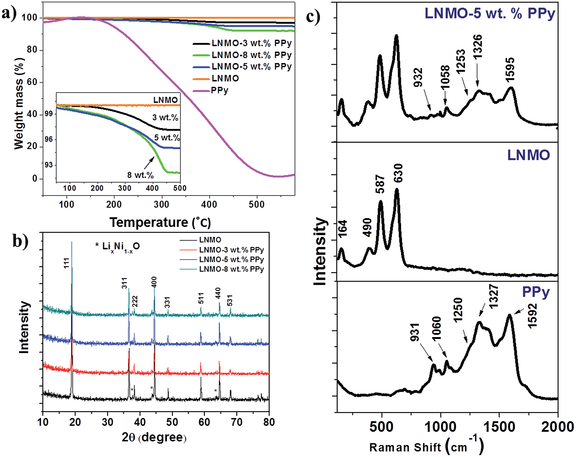 | ||
| Fig. 1 TGA curves, with the inset showing an enlargement of the indicated region (a), X-ray diffraction patterns (b), and Raman spectra (c) of the samples. | ||
The X-ray diffraction (XRD) patterns obtained from the bare LNMO and the LNMO–PPy composites are displayed in Fig. 1(b). The pattern of the bare LNMO corresponds to the cubic spinel structure (space group = Fd3m, JCPDS #32-0581). Very weak peaks, corresponding to LiNi1−xO2, are detected on the left shoulders of the peaks for the (400), (222) and (440) planes. This impurity is believed to originate from the oxygen loss in the samples at high annealing temperatures above 750 °C. Through the analysis of Mn 2p3/2 XPS spectra (see ESI Fig. S1†), the average oxidation state of Mn was calculated to be +3.91, according to the binding energy peak areas of Mn3+ and Mn4+. Consequently, the molecular formula can be determined to be LiNi0.454Mn1.546O4 based on the LiNi0.5−xMn1.5+xO4 spinel.34 No substantial difference in the XRD patterns between the bare LNMO and the PPy-coated LNMO composites was observed, demonstrating that the introduction of the PPy wrapping layer does not degrade the spinel crystalline structure of LNMO.
Raman spectroscopy confirmed the presence of PPy in the LNMO composites [Fig. 1(c)]. The bare LNMO exhibits characteristic bands located at 630 cm−1, 498 cm−1, and 164 cm−1 in the Raman spectrum.35 The Raman spectrum of the as-prepared PPy displays the vibrational band characteristic of the oxidized state at 1592 cm−1, which is related to a mixed vC![[double bond, length as m-dash]](https://www.rsc.org/images/entities/char_e001.gif) C and inter-ring vC–C vibration of short conjugation lengths, while the bands at 1327, 1253, and 1060 cm−1 are assigned to the ring deformation mode (δring) and the 931 cm−1 band is related to C–H out-of-the-plane deformation.36 The presence of similar PPy bands in the Raman spectrum of the LNMO–5 wt% PPy composite indicates that no chemical reaction between PPy and LNMO occurred during preparation.
C and inter-ring vC–C vibration of short conjugation lengths, while the bands at 1327, 1253, and 1060 cm−1 are assigned to the ring deformation mode (δring) and the 931 cm−1 band is related to C–H out-of-the-plane deformation.36 The presence of similar PPy bands in the Raman spectrum of the LNMO–5 wt% PPy composite indicates that no chemical reaction between PPy and LNMO occurred during preparation.
The morphologies of the bare LNMO and LNMO–5 wt% PPy were characterized by field emission scanning electron microscopy (FE-SEM). The low-magnification SEM image [Fig. 2(a)] reveals that the size of the LNMO particles is around 200–500 nm. The very clean and smooth surface of the bare LNMO can be seen in Fig. 2(c) at high magnification. In comparison, a relatively rough surface of the LNMO–5 wt% PPy composite was observed [Fig. 2(d)]. This indicates that a relatively uniform PPy layer had been coated successfully onto the outer surface of the LNMO.
 | ||
| Fig. 2 FESEM images of bare LNMO (a and c) and LNMO–5 wt% PPy (b and d) at various magnifications. | ||
Examination by transmission electron microscopy of LNMO–5 wt% PPy [Fig. 3(a) and (b)] confirmed the presence of a uniform PPy coating on all particles [Fig. 3(a)]. The crystal plane spacing of 0.47 nm indicated in the high resolution image, Fig. 3(b), is consistent with the LNMO (111) plane. The TEM data in Fig. 3(b) also demonstrate that the porous PPy layer is around 3 nm in thickness, and such a porous PPy layer may have resulted in a high surface area for the composite. This is demonstrated by the high surface area determined by Brunauer–Emmett–Teller (BET) gas adsorption/desorption of the PPy-coated composites. The surface areas are 25, 30, 32 and 35 m2 g−1 for the 0 wt%, 3 wt%, 5 wt% and 8 wt% PPy coated samples, respectively.
 | ||
| Fig. 3 TEM (a) and high resolution TEM (b) images of the LNMO–5 wt% PPy. SEM image and elemental maps (c) of Mn and N of the LNMO–5 wt% PPy composite. | ||
Fig. 3(c) presents the energy dispersive X-ray spectroscopy (EDS) mapping of LNMO–5 wt% PPy under SEM (with the SEM image on the bottom left side showing the mapping area). Within the resolution limit, the EDS mapping of positions of the element N, which corresponds to PPy, appears uniform, with the N close to the positions of the element Mn. This again confirms that the LNMO particles were uniformly wrapped up in the PPy layer.
Electrochemical results and discussion
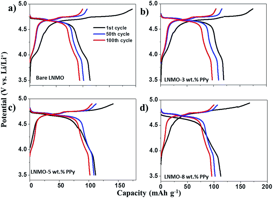
The electrochemical performances of the as-prepared samples were examined in the voltage range between 3.5 V and 4.9 V vs. Li/Li+ at a rate of 1.0 C (1 C = 140 mA g−1) up to 100 cycles at room temperature (25 °C). Fig. 4(a) shows the voltage profiles of the electrochemical cells in the range between 3.5 V and 4.9 V at a rate of 1.0 C. The first, 100th, and 200th charge–discharge curves of bare and surface modified LNMO with various contents of PPy are shown in Fig. 4(a). Two high-voltage plateaus can be observed at 4.70 V and 4.75 V, which can be associated with the Ni3+/2+ and Ni4+/3+ formal couples in LNMO.27,37 There is a small cathodic plateau located at 4.1 V, which is attributed to the Mn3+/4+ couple.4 No other peak is observed in Fig. 4(a), indicating that PPy does not lead to extra redox reactions in the tested voltage range, which means that the PPy remains stable during cycling and does not contribute to the discharge capacity. We also noticed that as the content of PPy coating increases, the polarization gap in the initial cycle becomes more apparent. This is probably because the thicker PPy layer would separate the active material from the electrolyte and slow the wetting with the electrolyte as it infiltrated into the porous battery, with the result that the active material could not initially charge–discharge fully. | ||
| Fig. 4 1st, 100th and 200th cycle charge–discharge curves of LNMO (a), LNMO–3 wt% PPy (b), LNMO–5 wt% (c), and LNMO–8 wt% PPy (d) at 1.0 C and room temperature (25 °C). | ||
The cyclic voltammetry (CV) curves of the bare LNMO and LNMO–5 wt% PPy shown in Fig. 5 are in good agreement with their charge–discharge curves. At a sweep rate of 0.1 mV s−1, the two main peaks corresponding to Ni3+/2+ and Ni4+/3+ are located around 4.7 V, while the small peak at 4.1 V is related to the existence of Mn3+/4+. The integrated area of the 4 V peak is much smaller than for the 4.7 V peaks, meaning that the main contribution to the total capacity and the total energy is from the Ni2+/4+ redox couple. After the introduction of PPy, no additional peak appears, indicating that PPy does not participate in redox reactions, so that it should be stable and not contribute to the capacity in the tested voltage range.
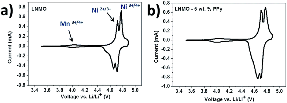 | ||
| Fig. 5 CV curves of the bare LNMO (a) and LNMO–PPy (b) for the 5th cycle; scan rate: 0.01 mV s−1. | ||
Fig. 6(a) compares the cycling performances of the bare LNMO and LNMO–PPy electrodes at the 1 C rate and room temperature (25 °C). The bare LNMO delivers a discharge capacity of 116 mA h g−1 at the first cycle. After that, the discharge capacity continuously decreases and drops to 94 mA h g−1 after 300 cycles, so that only 76.7% capacity retention is achieved. In contrast, reversible discharge capacities of 107.4, 112.9, and 99.1 mA h g−1 can be obtained for composites with 3%, 5%, and 8% PPy over 300 cycles at room temperature, corresponding to the respective capacity retentions of 83.2%, 91.0% and 85.7%. It is interesting to find that the specific charge capacity of the LNMO–PPy composite generally improves with the number of cycles, reaching a maximum after about 5 cycles, which is due to the progressive penetration of the electrolyte into the polymer, supplying sufficient quantities of anions for enhanced doping of the PPy.38
 | ||
| Fig. 6 Electrochemical performance of bare LNMO and LNMO–PPy composite electrodes cycled between 3.5 V and 4.9 V at 25 °C: (a) cycle life of LNMO and LNMO–PPy composites at the 1.0 C rate; (b) rate capabilities of LNMO and LNMO–5wt% PPy electrodes. | ||
The composite with 5 wt% PPy was chosen to test the rate capability, and it showed high Li+ storage at high current density as well [Fig. 6(b)]. For testing, the cell was first discharged–charged at a current density of 1.5 C for 6 cycles, and then at various current densities from 2.0 C to 5.0 C for 10 cycles each, before finally returning to 1.5 C. The reversible capacities are 105, 98, 92, and 85 mA h g−1 at 2.0, 3.0, 4.0, and 5.0 C, respectively. When the rate returned to 1.5 C, the specific capacity can be recovered up to 117 mA h g−1, indicating a very stable cycling performance. In comparison, the bare LNMO shows relatively poor capability at large current densities. It is accepted that the electrochemical performance at high rates is largely dependent on the electrical conductivity of the active material. Therefore, this superior electrochemical performance of LNMO–PPy should be ascribed to the high conductivity of the PPy layer. Herein, we should point out that the performance of our PPy coating sample compares favorably with some other reports in the literature. As mentioned above, some common inorganic materials have been proved to only work as a protective layer on the surface of active materials, but cannot enhance the rate capability for LNMO.8,13 On the other hand, carbon coating only leads to limited improvement,21 while other polymer coatings, such as polyimide,27 even made the battery performance worse than before the coating at 5 C and 10 C.
The electrochemical properties of the obtained samples were further tested at elevated temperature (55 °C). Before cycling, the cells were all stored in an oven for 10 h at 55 °C. The first, 50th and 100th charge–discharge curves of bare and surface modified LNMO with various contents of PPy are shown in Fig. 7. The electrode made from bare LNMO displays initial discharge and charge capacities of 116 mA h g−1 and 193 mA h g−1, respectively. Such huge charge consumption in the oxidation period can be ascribed to the formation of a large impedance.39 Previous work has reported that some undesirable interfacial reactions between LNMO and the liquid electrolyte are facilitated by storage at elevated temperature for a long time.5,15 The products from these harmful reactions are easy to deposit on the surface of the spinel cathode, resulting in the polarization resistance and large impedance. Furthermore, at the high operating voltage of 5 V, spinel cathodes would accelerate the formation of HF in the electrolyte. The increased concentration of HF would enhance the dissolution of Mn in the LNMO electrode material, causing poor electrochemical performance.5 As shown in Fig. 7(b)–(d), the electrolyte decomposition and concomitant film deposition on the PPy coated samples is significantly suppressed as the strong polarization gap disappears in the initial cycle. The initial coulombic efficiencies of LNMO–3 wt% PPy, LNMO–5 wt% PPy, and LNMO–8 wt% are 67.5%, 84.1%, and 79.1%, respectively. It should be noted that, although the higher temperature can promote Li+ transmission and accelerate the soaking of the electrolyte into the electrode, the thicker PPy layer may still obstruct electrode wetting. Therefore, the LNMO–5 wt% PPy composite presents higher initial columbic efficiency than LNMO–8 wt% PPy.
 | ||
| Fig. 7 1st, 50th, and 100th cycle charge–discharge curves of LNMO (a), LNMO–3 wt% PPy (b), LNMO–5 wt% (c), and LNMO–8 wt% PPy (d) at 1.0 C and elevated temperature (55 °C). | ||
Fig. 8(a) compares the cycling performances of the bare LNMO and LNMO–PPy composites at the 1 C rate and elevated temperature (55 °C). The bare LNMO delivers a discharge capacity of 94.5 mA h g−1 and exhibits a capacity retention of only 81.4% after 100 cycles. All the PPy-coated LNMO composites show better capacity retention than that of the bare sample. Among these cells, the LNMO–5 wt% PPy has the best electrochemical performance. After 100 cycles, it still retains a reversible capacity of 105.2 mA h g−1, corresponding to the capacity retention of 91%. The capacity retentions of LNMO–3 wt% PPy and LNMO–8 wt% PPy are 83% and 86% after 100 cycles, respectively. The substantially improved cycling performance should be ascribed to the suppression of the dissolution of manganese and the electrode polarization, with the effective protection of the LNMO surface by the nano-architecture of the PPy wrapping layer. To understand this behavior, AC impedance measurements and chemical analyses were performed on the electrodes after cycling, which will be discussed in detail later.
 | ||
| Fig. 8 Cycling performance of LNMO, LNMO–3 wt% PPy, LNMO–5 wt%, and LNMO–8 wt% PPy at 1.0 C and elevated temperature (55 °C): (a) specific capacity and (b) coulombic efficiency. | ||
The coulombic efficiencies of the four samples are also summarized and compared in Fig. 8(b). The coulombic efficiencies of all the composites cycled at elevated temperature are obviously higher than those of the bare LNMO sample, which confirms that the PPy coating can effectively suppress the serious resistive effects of the surface film under harsh conditions: the highly oxidizing environment (>4.5 V) and the elevated temperature.11 This surface film causes thick solid electrolyte interphase (SEI) formation on the surface of the active material, thus leading to low coulombic efficiencies. After 5 cycles, however, the coulombic efficiencies of all the cells with PPy coating can reach 92%, while that of bare LNMO is only around 90%.
AC impedance analysis was conducted to explain the difference in performance shown in Fig. 9. The Nyquist plots before cycling consist of a semicircle and a straight line. The diameters of the semicircles for the bare LNMO cell and LNMO–5 wt% PPy electrodes before cycling are 32 Ω and 45 Ω, respectively. After 300 cycles, two depressed semicircles were observed. The impedance data collected after cycling were fitted with the equivalent circuit shown in Fig. 9(a). In brief, they reflect three major constants:40Re is the solution resistance due to electrolyte impedance and electrical contacts, which can be obtained from the intercept of the semicircle at high frequency with the x-axis. The semicircle in the high frequency region (f > 300 Hz), Rfilm, reflects the contact resistances between the active materials, the electrolyte and the current collector. The semicircle in the middle frequency range (0.1 Hz < f < 10 Hz), Rct, is attributed to the charge transfer resistance.11 Their values calculated from the Nyquist plots are summarized in Table 1. The decrease in the resistance after cycling confirms that the incorporation of PPy is an effective method for enhancing the electron transport of LNMO, and consequently leads to a significant improvement in the electrochemical performance.
 | ||
| Fig. 9 Nyquist plots of pristine LNMO and LNMO–5 wt% PPy electrodes before cycling and after cycling at 55 °C and 25 °C. The inset in (a) is the equivalent circuit used to interpret the data. | ||
| R e (Ω) | R film (Ω) | R ct (Ω) | |
|---|---|---|---|
| LNMO (25 °C) | 7.41 | 63.16 | 124.79 |
| LNMO–5 wt% PPy (25 °C) | 6.23 | 18.59 | 72.63 |
| LNMO (55 °C) | 2.25 | 132.87 | 203.58 |
| LNMO–5 wt% PPy (55 °C) | 2.14 | 123.49 | 170.45 |
Interestingly, two condensed semicircles were observed in the spectrum of the bare LNMO electrode at 55 °C before cycling, which indicates that a small portion of the electrolyte had been decomposed and been directly deposited on the surface of the electrode after storage at high temperature for 10 h.15 The electrolyte decomposition might have already formed a SEI layer on the active material before cycling, which is in accordance with the electrochemical response of the electrode, which is discussed above. In contrast, the LNMO–5 wt% PPy cell only shows one semicircle with a diameter of 42 Ω, indicating a faster interfacial charge transfer.
The cells after 100 cycles at 55 °C were opened up to observe the differences on the lithium anode surface. Much black material was found on the surface of the lithium metal and the separator in the bare LNMO cell [Fig. 10(a)], while the lithium foil in the LNMO–5 wt% cell is clear. The Li anode in the cell with the bare LNMO was further analyzed by energy dispersive spectroscopy (EDS) [Fig. 10(b)], and strong Mn and Ni peaks were clearly detected. This is believed to be due to dissolution of Mn3+/Mn4+ and Ni2+ in the active material into the electrolyte, which then migrates to and is deposited on the lithium anode. In contrast, the LNMO–PPy composite showed a negligible amount of Mn and Ni deposition on the lithium foil (see Fig. S2†). Therefore, we believe that a uniform PPy coating on the surface of the LNMO not only can act as an ion-conductive layer, but also acts to suppress the decomposition of Mn and Ni at elevated temperatures, as demonstrated in Fig. 11.
 | ||
| Fig. 10 (a) Photographs of the lithium anodes [LNMO–5 wt% (A) and bare LNMO (B)] and the corresponding separators, (b) EDS spectrum of the lithium anode in the coin cell of the bare LNMO sample after 100 cycles at 55 °C. | ||
 | ||
| Fig. 11 Schematic illustration of how the PPy layer acts as a conductive and protective layer to suppress the dissolution of Mn, as well as the unwanted electrolyte decomposition at elevated temperature. | ||
Based on the discussions above, PPy is demonstrated to be an effective additive for improving the electrochemical performance of the LNMO cathode material. The promising electrochemical performance of LNMO/PPy can be ascribed to three reasons (demonstrated in Fig. 11): (1) PPy is a conductive polymer and can work as a conductive additive, thus improving the conductivity of bare LNMO; (2) the dissolution of transition metals into the electrolyte can be suppressed by the PPy layer; and (3) the external PPy layer on the LNMO particles can further relieve the serious electrolyte decomposition for the active material, and thus improve the initial coulombic efficiency at elevated temperature.
Conclusions
An innovative way to improve the electrochemical performance of LNMO by depositing a conductive PPy coating has been demonstrated. It is suggested that the LNMO with 5 wt% PPy coating shows the best cycle life and coulombic efficiency compared to the bare LNMO and the LNMO with other PPy contents. The results of chemical analysis of the lithium foil anode after cycling confirm that the presence of the PPy coating layer is responsible for the suppression of manganese and nickel dissolution in the LNMO during Li+ insertion/de-insertion processes. The PPy layer can also protect the electrode from the products that originate from the decomposition of the electrolyte at elevated temperature, and it thus leads to higher coulombic efficiencies. In addition, a uniform PPy layer is also proved to be an effective conductive agent for the electrode, leading to attractive lithium storage capability at high charge–discharge rates. In consideration of the superior electrical performance with the PPy coating, we believe the LNMO–PPy composite has potential as a high-energy and high-power cathode material for the lithium-ion battery.Acknowledgements
Financial support is provided by an Australian Research Council (ARC) Discovery Project (DP110103909). This work was also supported by a special financial grant from the China Postdoctoral Science Foundation (2013T60795), the Guangdong Province Science & Technology Bureau (Industry-Education-Research Project, grant no. 2012B050300004). The authors acknowledge the use of facilities within the UOW Electron Microscopy Centre. The authors also thank Dr Tania Silver for critical reading of the manuscript.Notes and references
- J. M. Tarascon and M. Armand, Nature, 2001, 414, 359–367 CrossRef CAS PubMed.
- M. Armand and J. M. Tarascon, Nature, 2008, 451, 652–657 CrossRef CAS PubMed.
- J. B. Goodenough, Acc. Chem. Res., 2013, 46, 1053–1061 CrossRef CAS PubMed.
- L. Zhou, D. Y. Zhao and X. W. Lou, Angew. Chem., Int. Ed., 2012, 51, 239–241 CrossRef CAS PubMed.
- N. P. W. Pieczonka, Z. Y. Liu, P. Lu, K. L. Olson, J. Moote, B. R. Powell and J. H. Kim, J. Phys. Chem. C, 2013, 117, 15947–15957 CAS.
- J. B. Goodenough and Y. Kim, ChemInform, 2010, 41 DOI:10.1002/chin.201031217.
- R. Prasad, R. Benedek, A. J. Kropf, C. S. Johnson, A. D. Robertson, P. G. Bruce and M. M. Thackeray, Phys. Rev. B: Condens. Matter Mater. Phys., 2003, 68, 012101 CrossRef.
- X. Hao and B. M. Bartlett, J. Electrochem. Soc., 2013, 160, A3162–A3170 CrossRef CAS PubMed.
- R. Benedek, M. M. Thackeray, J. Low and T. Bucko, J. Phys. Chem. C, 2012, 116, 4050–4059 CAS.
- Y. K. Sun, K. J. Hong, J. Prakash and K. Amine, Electrochem. Commun., 2002, 4, 344–348 CrossRef CAS.
- J. Mun, T. Yim, K. Park, J. H. Ryu, Y. G. Kim and S. M. Oh, J. Electrochem. Soc., 2011, 158, A453–A457 CrossRef CAS PubMed.
- Y. K. Sun, Y. S. Lee, M. Yoshio and K. Amine, J. Electrochem. Soc., 2003, 150, L11 CrossRef CAS PubMed.
- J. C. Arrebola, A. Caballero, L. Hernan and J. Morales, J. Power Sources, 2010, 195, 4278–4284 CrossRef CAS PubMed.
- B. Huang, X. H. Li, Z. X. Wang, H. J. Guo, X. H. Xiong and J. X. Wang, J. Alloys Compd., 2014, 583, 313–319 CrossRef CAS PubMed.
- T. Noguchi, I. Yamazaki, T. Numata and M. Shirakata, J. Power Sources, 2007, 174, 359–365 CrossRef CAS PubMed.
- Z. Qiao, O. Sha, Z. Y. Tang, J. Yan, S. L. Wang, H. B. Liu, Q. Xu and Y. J. Su, Mater. Lett., 2012, 87, 176–179 CrossRef CAS PubMed.
- D. Liu, J. Trottier, P. Charest, J. Frechette, A. Guerfi, A. Mauger, C. M. Julien and K. Zaghib, J. Power Sources, 2012, 204, 127–132 CrossRef CAS PubMed.
- D. Liu, Y. Bai, S. Zhao and W. Zhang, J. Power Sources, 2012, 219, 333–338 CrossRef CAS PubMed.
- J. Liu and A. Manthiram, Chem. Mater., 2009, 21, 1695–1707 CrossRef CAS.
- T. Y. Yang, N. Q. Zhang, Y. Lang and K. N. Sun, Electrochim. Acta, 2011, 56, 4058–4064 CrossRef CAS PubMed.
- X. Fang, M. Ge, J. Rong and C. Zhou, J. Mater. Chem. A, 2013, 1, 4083–4088 CAS.
- G. X. Wang, L. Yang, Y. Chen, J. Z. Wang, S. Bewlay and H. K. Liu, Electrochim. Acta, 2005, 50, 4649–4654 CrossRef CAS PubMed.
- H. Guo, L. Liu, H. Shu, X. Yang, Z. Yang, M. Zhou, J. Tan, Z. Yan, H. Hu and X. Wang, J. Power Sources, 2014, 247, 117–126 CrossRef CAS PubMed.
- M. Sugita, H. Noguchi, Y. Soejima and M. Yoshio, Electrochemistry, 2000, 68, 587–590 CAS.
- J. U. Kim, I. S. Jeong, S. I. Moon and H. B. Gu, J. Power Sources, 2001, 97–98, 450–453 CrossRef CAS.
- J. H. Park, J. H. Cho, E. H. Lee, J. M. Kim and S. Y. Lee, J. Power Sources, 2013, 244, 442–449 CrossRef CAS PubMed.
- J. H. Cho, J. H. Park, M. H. Lee, H. K. Song and S. Y. Lee, Energy Environ. Sci., 2012, 5, 7124–7131 CAS.
- Y. Kudoh, Synth. Met., 1996, 79, 17–22 CrossRef CAS.
- Y. S. Cohen, M. D. Levi and D. Aurbach, Langmuir, 2003, 19, 9804–9811 CrossRef CAS.
- Z. P. Guo, J. Z. Wang, H. K. Liu and S. X. Dou, J. Power Sources, 2005, 146, 448–451 CrossRef CAS PubMed.
- S. Y. Chew, Z. P. Guo, J. Z. Wang, J. Chen, P. Munroe, S. H. Ng, L. Zhao and H. K. Liu, Electrochem. Commun., 2007, 9, 941–946 CrossRef CAS PubMed.
- S. L. Chou, X. W. Gao, J. Z. Wang, D. Wexler, Z. X. Wang, L. Q. Chen and H. K. Liu, Dalton Trans., 2011, 40, 12801–12807 RSC.
- Y. Deng, Z. Li, Z. Shi, H. Xu, F. Peng and G. Chen, RSC Adv., 2012, 2, 4645–4647 RSC.
- T. F. Yi and X. G. Hu, J. Power Sources, 2007, 167, 185–191 CrossRef CAS PubMed.
- D. Aurbach, B. Markovsky, Y. Talyossef, G. Salitra, H. J. Kim and S. Choi, J. Power Sources, 2006, 162, 780–789 CrossRef CAS PubMed.
- M. J. L. Santos, A. G. Brolo and E. M. Girotto, Electrochim. Acta, 2007, 52, 6141–6145 CrossRef CAS PubMed.
- K. Amine, H. Tukamoto, H. Yasuda and Y. Fujita, J. Electrochem. Soc., 1996, 143, 1607–1613 CrossRef CAS PubMed.
- P. Novak, K. Muller, K. S. V. Santhanam and O. Haas, Chem. Rev., 1997, 97, 207–281 CrossRef CAS PubMed.
- N. M. Hagh, F. Cosandey, S. Rangan, R. Bartynski and G. G. Amatucci, J. Electrochem. Soc., 2010, 157, A305–A319 CrossRef CAS PubMed.
- D. Aurbach, K. Gamolsky, B. Markovsky, G. Salitra, Y. Gofer, U. Heider, R. Oesten and M. Schmidt, J. Electrochem. Soc., 2000, 147, 1322–1331 CrossRef CAS PubMed.
Footnote |
| † Electronic supplementary information (ESI) available. See DOI: 10.1039/c4ta04018j |
| This journal is © The Royal Society of Chemistry 2015 |