
 Open Access Article
 This Open Access Article is licensed under a
 Creative Commons Attribution 3.0 Unported Licence
Rational design of molecularly imprinted polymers†
Tine
Curk‡
ab,
Jure
Dobnikar
*a and
Daan
Frenkel
b
aInternational Research Center for Soft Matter, Beijing University of Chemical Technology, Beijing, China. E-mail: jd489@cam.ac.uk
bDepartment of Chemistry, University of Cambridge, Cambridge, UK
First published on 17th September 2015
Abstract
Molecular imprinting is the process whereby a polymer matrix is cross-linked in the presence of molecules with surface sites that can bind selectively to certain ligands on the polymer. The cross-linking process endows the polymer matrix with a chemical ‘memory’, such that the target molecules can subsequently be recognized by the matrix. We present a simple model that accounts for the key features of this molecular recognition. Using a combination of analytical calculations and Monte Carlo simulations, we show that the model can account for the binding of rigid particles to an imprinted polymer matrix with valence-limited interactions. We show how the binding multivalency and the polymer material properties affect the efficiency and selectivity of molecular imprinting. Our calculations allow us to formulate design criteria for optimal molecular imprinting.
Introduction
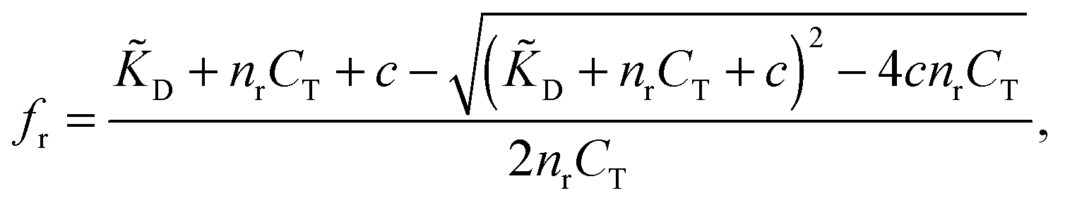
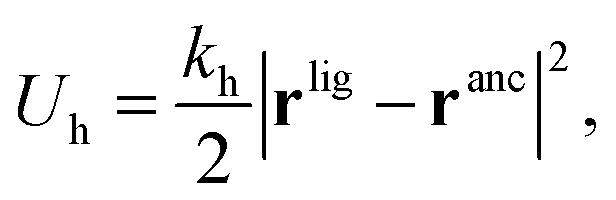
The term ‘Molecularly Imprinted Polymers’ (MIPs) is used to denote polymer matrices that have been “imprinted”, i.e. cross-linked in the presence of a template molecule, thereby acquiring selective affinity for its template. MIPs are usually made by free-radical co-polymerisation of ligands and cross-linkers in the presence of template molecules. The molecule-matrix interaction may exploit covalent binding, ionic interactions,1 hydrogen bonding,2 π–π stacking interactions,3 hydrophobic interactions,4 and metal-ion chelation.5 In 1930 Polyakov introduced this technique6 to imprint silica matrices with benzene. However, the technique has only become widely used in recent decades.7–10 The use of MIPs is related to the fact that they can be designed for highly selective recognition. Moreover, they combine thermal and chemical stability with ease of preparation, and hence low production costs.MIPs have been used in applications such as solid-phase extraction,11 chiral separation,12 and catalysis.13 They can act as molecular sensors,8,10,14 and mimic antibodies or enzymes.8 They can selectively bind drugs,15–17 proteins,18 or even whole bacteria.19,20Fig. 1 shows a schematic representation of the imprinting and subsequent recognition process. The efficiency of the molecular recognition process depends on a number of parameters: (1) the initial ligand concentration c, (2) the template–ligand binding affinity KD, and (3) the stiffness of the polymer matrix kh.
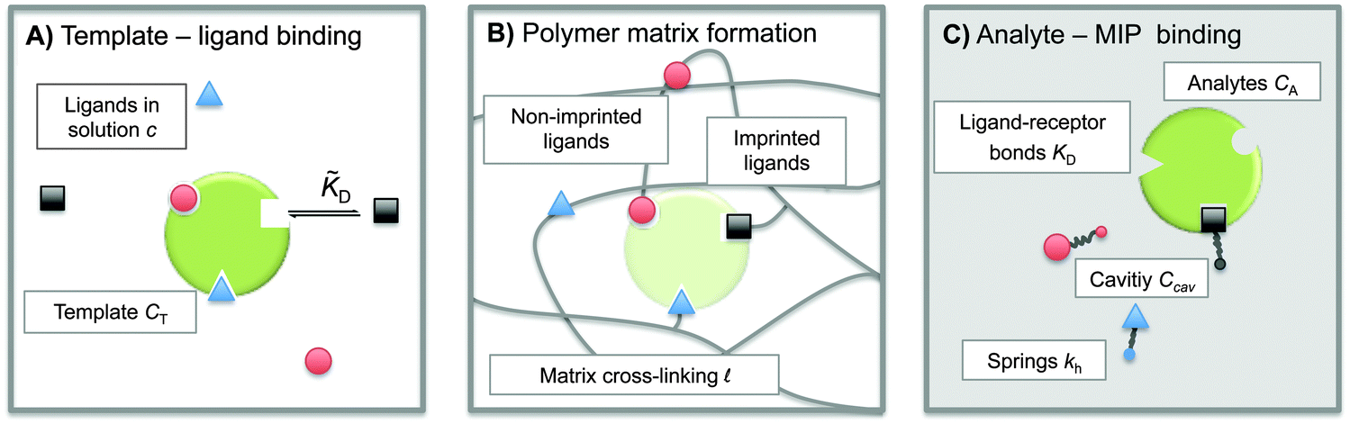 | ||
| Fig. 1 Schematic representation of the molecular imprinting process: (A) binding of ligands (functional monomers) from the solution to the template with specific receptors (binding sites), (B) cross-linking and extracting of the template to create an imprinted cavity with ligands attached to the polymer matrix, and (C) re-binding of an analyte to the cavity. | ||
Clearly, it is important to maximize the selectivity of MIPs, but in experiments MIPs are often optimized by trial and error. In fact, the theoretical picture is rather fragmented as existing theoretical models for MIPs do not consider the imprinting process as a whole, but rather tend to focus on individual steps in their mode of action.21–27 Moreover, the atomistic and coarse-grained simulations of molecular imprinting that have been reported28–33 focused mostly on specific MIPs and did not explore generic trends that would allow us to arrive at general design principles.
Here, we present a generic, coarse-grained statistical mechanics model that captures the key features of molecular recognition. The model provides an integrated description of the MIP formation process and of the subsequent binding of analytes. For the simplest case of divalent particles (i.e. particles with 2 receptors), we derive analytical expressions for the binding free energy and, from that, the adsorption isotherm of analytes on a MIP. For the general case of multivalent particles, we use Monte Carlo simulations to obtain the adsorption isotherms – representative snapshots from the simulations are shown in Fig. 3 below. Two important measures of the quality of a MIP are: (i) how much more efficient is binding of a given analyte to imprinted (MIP) than to a non-imprinted matrix (NIP), and (ii) how well can we separate two analytes that are only slightly different (e.g., of the same size and with the same number – but different spatial patterns – of the receptors). In order to address these questions, we evaluate standard measures of MIP specificity, such as the imprinting factor (IF) and the separation factor (SF), as a function of matrix and analyte properties and identify the optimal range of the control parameters such as the template and ligand concentrations and polymer matrix stiffness. Our work provides insight into the generic features of MIP operation and leads to a set of simple design principles.
Model
To construct a simple model for MIPs we describe the template and analyte molecules as impenetrable spheres with a diameter σ. At fixed (but otherwise arbitrary) positions on the surface of these spheres there are binding sites (referred to as ‘receptors’) that can bind to the functional monomers (referred to as ligands), see Fig. 1. In step A of the MIP formation, the template receptors bind ligands from the solution, while in step B the ligands are tethered via cross-linking, i.e. a polymer network is formed and ligands attached to the dangling ends of the network. In a MIP application C the receptors on analyte molecules bind to matrix-grafted ligands. The interactions between ligands and receptors are assumed to be valence limited: each receptor can bind to at most one ligand with a ‘hybridization free energy’ ΔG. Moreover, we assume that individual binding events are uncorrelated, i.e. we do not consider allosteric effects between different binding events. We use the term “hybridization free energy” for binding of individual ligands to distinguish it from the free-energy change associated with the binding of entire analytes to the cavity. We essentially consider templates and analytes as multivalent entities and our model approach is similar to that of Whitesides et al.34 The chirality can be encoded by the specific positions of the distinguishable binding sites, see ESI† for an example of enantiomeric separation.In what follows we use the standard notation for the inverse temperature: β ≡ 1/kBT with kB the Boltzmann constant and T the absolute temperature. Hybridization free energies for ligand–receptor bonds can be deduced from experimental data for binary association in solution, which yield the dissociation constant KD = ρ0eβΔG, where ρ0 = 1 M is the standard concentration. We note that the ligand–receptor dissociation constant in the pre-polymerization solution ![[K with combining tilde]](https://www.rsc.org/images/entities/i_char_004b_0303.gif) D can in principle be different from the one in a formed MIP KD if the conditions such as solvent, pH, salt concentration, or temperature are different. Corrections for the fact that the ligands and receptors have an excluded volume and are tethered to a surface can be computed (see ref. 35 and 36).
D can in principle be different from the one in a formed MIP KD if the conditions such as solvent, pH, salt concentration, or temperature are different. Corrections for the fact that the ligands and receptors have an excluded volume and are tethered to a surface can be computed (see ref. 35 and 36).
Using standard chemical equilibrium theory we can compute the amount of ligands adsorbing to the templates in step A, which depends on the ligand dissociation constant under the conditions of the imprinting phase, D, on the concentrations of templates CT and on c, the original concentration of ligands in solution (see ESI†). The fractional occupancy of receptors fr (the probability that a given receptor is bound to a ligand) is
 | (1) |
In our model we must account for the effect of the deformability of the matrix and for the directionality of the ligand–template interaction. To this end, we model MIPs as soft, deformable matrices that contain cavities imprinted by specific ligands (Fig. 1(C)). The ligands grafted to the matrix can fluctuate around their equilibrium positions due to the thermal fluctuations. We call the equilibrium positions of the imprinted ligands their “anchors”. In order to bind to receptors on the analyte, the ligands need to be displaced from their anchors, which increases the elastic free-energy of the matrix by an amount Uh. Following Rubinstein and Colby,37 we assume that the ligand–matrix interaction only depends on the distance between the receptor and the anchor and that it can be replaced by a harmonic spring:
 | (2) |
 | (3) |
 the effective elastic modulus, σ the characteristic cavity size (template size) and
 ![[small script l]](https://www.rsc.org/images/entities/char_e146.gif) the mesh size, that is the cross-linking distance for gels or the distance between adjacent, unbound strands for glassy polymers. Si(x) is the sine integral function, which can be well approximated by a polynomial Si(x) ≈ x − x3/18; x ≪ π and a constant Si(x) ≈ π/2; x ≫ π.
the mesh size, that is the cross-linking distance for gels or the distance between adjacent, unbound strands for glassy polymers. Si(x) is the sine integral function, which can be well approximated by a polynomial Si(x) ≈ x − x3/18; x ≪ π and a constant Si(x) ≈ π/2; x ≫ π.
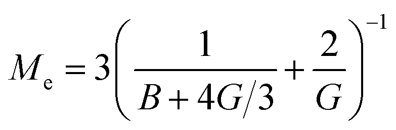
We see that kh depends weakly on the template (cavity) size σ because the relative fluctuations of 2 ligands will decrease if the two ligands are closer than the mesh size . For flexible polymer gels Me ≈ kBT/3 (ref. 37) and large particles σ > the spring constant is determined simply by the cross-linking distance kh ≈ πkBT/2. Eqn (3) is important because, as we show below, it allows us to predict the effect of the stiffness of the matrix on the selectivity of MIPs. We will focus on the case where particles are rigid, however, the present model can be applied also to soft particles (such as proteins) where receptor positions on the particle itself are fluctuating (fluctuations characterised by spring constant kparth). In this case we could map (to the first order) a soft particle and a soft matrix to the current model of a hard particle and an “effective” softer matrix 1/keffh = 1/kh + 1/kparth.
In what follows we first focus on a single cavity system and calculate the free energy of binding an analyte. Afterwards we extend the picture to the whole polymer matrix and calculate corresponding binding affinities and adsorption isotherms.
Binding free energy
The binding free energy F for the analyte–cavity system can be decomposed into a specific interaction part Fcav due to the bond formation and a non-specific part Fns, which includes other possible contributions to particle adsorption such as excluded volume, hydrophobic, electrostatic or van der Waals interactions between the particle and the polymer matrix. The non-specific term depends on the particle size, shape and is thus similar for similar analytes. These terms add to the binding free energy, however as we will show below, they cancel out in the ratios defining the imprinting and separation factors – as long as the analyte particles are similar-enough.23 For differently shaped analytes a study reported by Simon et al.38 concluded that the effect of the analyte shape becomes less important when the number of binding sites (receptors) on the analyte is larger than 2. Therefore, we only evaluate the specific part of the binding free energy due to bond formation. In the divalent case the specific Fcav2 can be calculated analytically.The position rp and orientation Ωp of a rigid particle uniquely define the positions of all binding sites on its surface rbsi. When the particle approaches the cavity, bonds between the binding sites i and the ligands j can be formed – forming a bond results in a lowering of the free energy by an amount equal to the hybridization free energy ΔGij, but forming a bond also costs free energy because (in general) the ligand must be displaced from its equilibrium position rancj to rligj = rbsi: the corresponding free energy cost is given by (2). To compute the overall binding free energy, we need to compute the ratio of the partition function for the case where one or more ligands are bound to the particle, to the one for the case with no ligands bound.
This expression does not yet include the partition function of the unbound particles: this will later be accounted for through the chemical potential of the free particles. The partition function depends on the distribution of the binding sites on the particle rbs and on the arrangement of ligand anchors in the cavity ranc. To obtain the partition function we must sum over all particle positions and orientation and over all possible bonding arrangements:
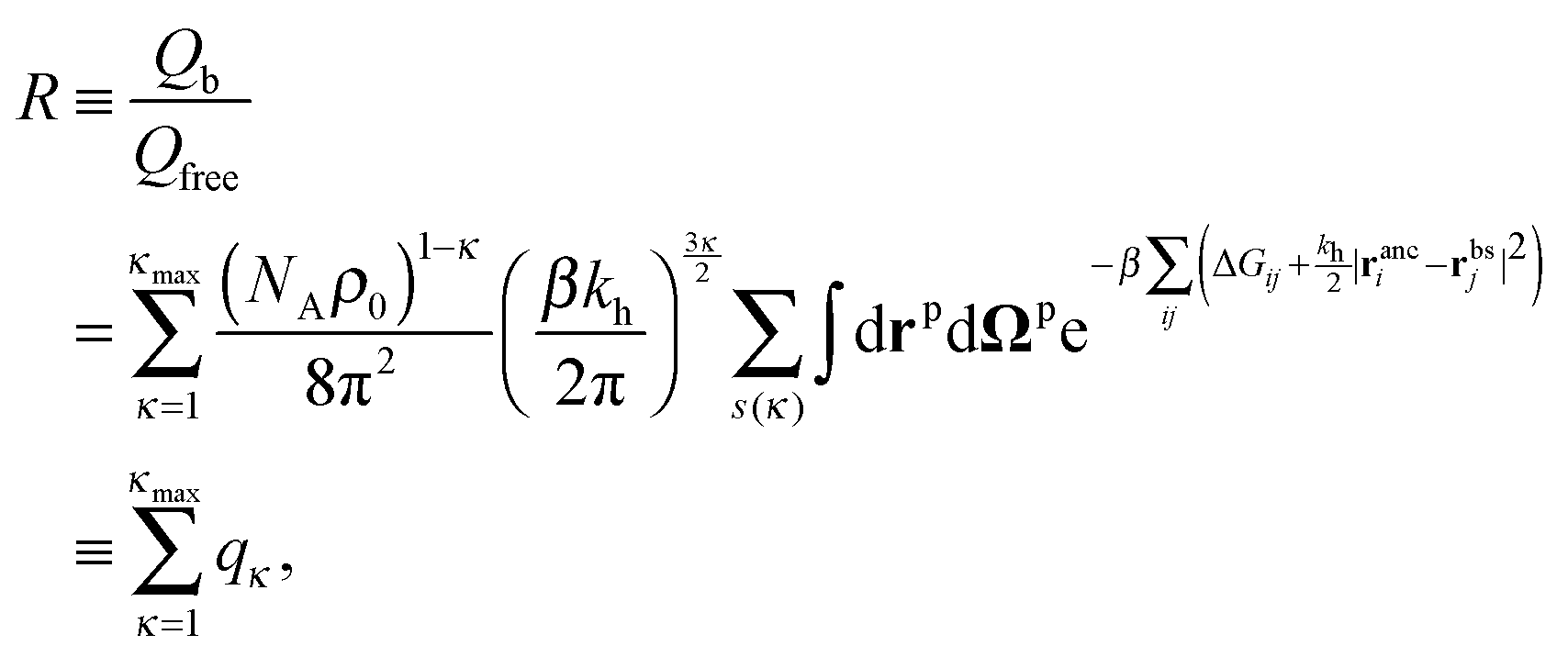 | (4) |
 is directly related to the specific part of the binding free energy:
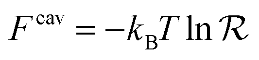 | (5) |
 | (6) |
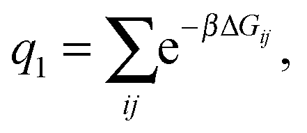
As a single bond cannot create a static stress in the matrix, q1 does not depend on the matrix stiffness kh. A similar result was reported by Tanaka et al. for the case of imprinted hydrogels.25 The simplest non-trivial term is the two-bond partition function. For any chosen combination of two binding sites  and two ligands
  , there are two possible ways of forming two bonds. The total two-bond partition function in a system where there is more than one way to make two bonds is a sum of all possible two-bond pairs ij, i′j′,
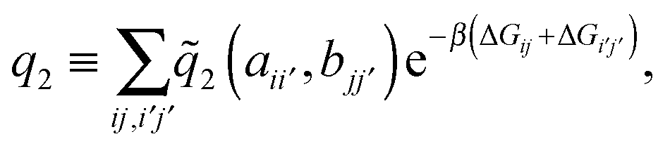 | (7) |
 the distance between the binding sites, and
  the distance between the two ligand anchors (see the inset of Fig. 2(a)). The configurational part of the partition function
 ![[q with combining tilde]](https://www.rsc.org/images/entities/i_char_0071_0303.gif) 2(a, b) is a solution of a coupled Gaussian integral and can be calculated analytically (see ESI†):
2(a, b) is a solution of a coupled Gaussian integral and can be calculated analytically (see ESI†):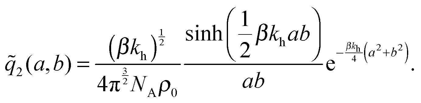 | (8) |
2(a, b)ρ0/KD, with 2(a, b) precisely the configurational part of the partition function given by (8). Our analytical approach thus enables us to calculate the internal association constant Kintra for divalent binding. This result goes beyond the scope of molecular imprinting, it is a general solution and applicable to any divalent entity binding within the harmonic approximation (2).
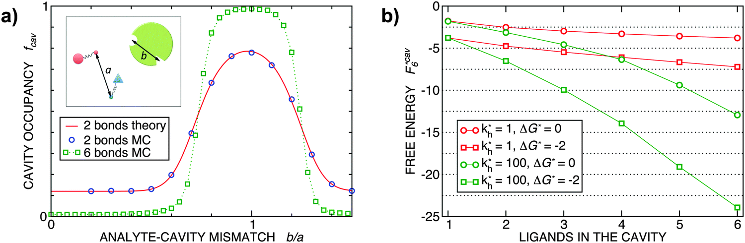 | ||
Fig. 2 (a) Multivalency. The cavity occupancy fcav as a function of the imprinting mismatch b/a. The red solid line represents analytical calculations (4)–(9). The symbols depict the results of Monte Carlo simulations: blue circles for the divalent, green squares for the hexavalent case. Parameters: matrix stiffness 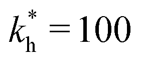 , analyte concentration in solution , analyte concentration in solution  , and the bond energies in the divalent/hexavalent case , and the bond energies in the divalent/hexavalent case  , ,  . (b) Incomplete cavities. The specific binding free energy . (b) Incomplete cavities. The specific binding free energy  of a hexavalent analyte as a function of the number of ligands imprinted in the cavity. The results are for two values of of a hexavalent analyte as a function of the number of ligands imprinted in the cavity. The results are for two values of  (red: soft gel, green: stiff gel) and for two values of ligand binding strength ΔG* (circles: weaker bonds, squares: stronger bonds). (red: soft gel, green: stiff gel) and for two values of ligand binding strength ΔG* (circles: weaker bonds, squares: stronger bonds). | ||
 | ||
Fig. 3 Simulation snapshots. (a) Imprinting phase: ligands (small balls, red when free and blue when bound) bind to the divalent templates (orange balls with cyan receptors). The ligand positions are subsequently frozen and templates extracted to form the cavities (MIP) shown in (b) and (c) as transparent blobs. (b) Re-binding of templates to MIP. (c) Binding of templates to the non-imprinted matrix (NIP). Snapshots show only a small part of the simulated system. (d) Adsorption isotherms. Average number of bound divalent (tetravalent in the inset) analytes  depending on the concentration of analytes in solution depending on the concentration of analytes in solution  . Solid lines depict the analytical prediction (12)–(14), and the symbols are for simulation results (black circles: re-binding of templates (b = a) to MIPs as shown in the snapshot (b)), green diamonds: binding of different analytes . Solid lines depict the analytical prediction (12)–(14), and the symbols are for simulation results (black circles: re-binding of templates (b = a) to MIPs as shown in the snapshot (b)), green diamonds: binding of different analytes  to MIPs, and red squares: binding of templates to a NIP – as shown in the snapshot (c). The parameters: to MIPs, and red squares: binding of templates to a NIP – as shown in the snapshot (c). The parameters:  , c* = 0.02, CT = 0.01, , c* = 0.02, CT = 0.01,  . The snapshots represent a configuration of bound analytes at . The snapshots represent a configuration of bound analytes at  with the system size V = (12.6σ)3. Inset in (d) shows isotherms of tetravalent particles binding at with the system size V = (12.6σ)3. Inset in (d) shows isotherms of tetravalent particles binding at  . . | ||
In the limit of soft matrices kh ≪ kBT/b2, where thermal fluctuations are greater then the analyte size, the specificity towards analyte geometry is lost  . This is the regime where only the number of ligands in the cavity (or the number of receptors on the analyte) remains important, not their spatial positions. In this limit the rotational degrees of freedom can be neglected, such a model of molecular imprinting has been considered in ref. 25 and 26.
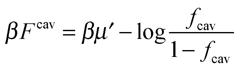
If we assume that all binding cavities are identical and independent, the number of adsorbed analyte particles is determined by the binding free energy F and by the chemical potential μ of the analyte. We recover the simple Langmuir expression for the fraction of occupied cavities:
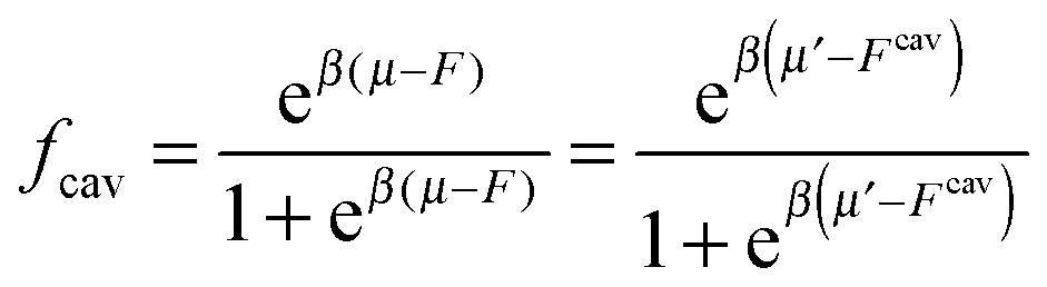 | (9) |
 . The simulation code to compute the binding free energies for the arbitrary template and analyte parameters is freely available online at http://github.com/tc387/mipsp.
Cavity binding results and discussion
In order to cast our results in the most general form, we introduce the following dimensionless quantities: matrix stiffness , dissociation constant
 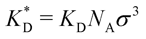 , concentrations c* = cNAσ3, distances a* = a/σ and analyte–cavity binding free energy ΔF* = F/kBT + ln(σ3NAρ0). The single bond hybridization free energy then follows
 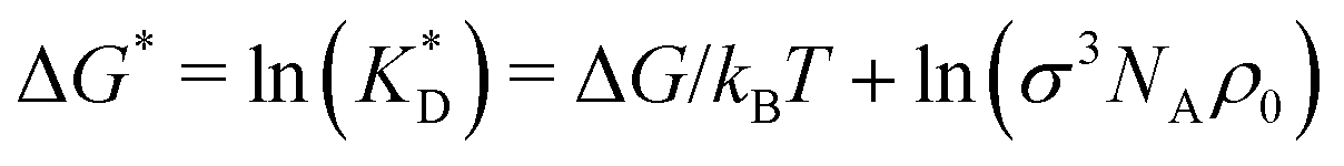 . For example, if the template size is σ = (ρ0NA)−1/3 = 1.18 nm the rescaled and standard values of the equilibrium constant, concentration and free energy remain the same. For dilute solutions of analytes we can assume an ideal solution and the chemical potential becomes
 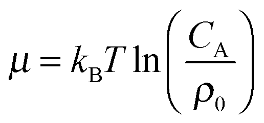 , with CA the molar concentration of analytes, rescaling
 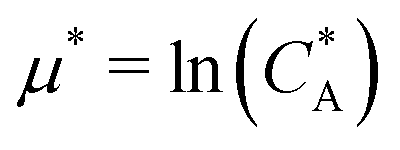 .
.
MIPs that have been cross-linked in the presence of specific template particles will adsorb analytes that have a structure similar to the template: the greater the similarity between the template and the target particle, the larger the average occupancy fcav of the cavities imprinted by the template particles. In the case of particles with two binding sites, we can compute fcav analytically (eqn (4)–(9)). In Fig. 2(a) we compare these analytical calculations with Monte Carlo simulations. The good agreement between analytical results and simulations allows us to validate the Monte Carlo approach. For a particle with 6 binding sites, the analytical calculations are no longer tractable, but the MC simulations in Fig. 2 show that imprinting with a higher valency leads to a much stronger discrimination. In both cases, the cavities have a fixed ligand distribution that is imprinted by the template particle. The analytes are assumed to have the same geometry as the template but their sizes are rescaled by a factor b/a (the “imprinting mismatch”). Not surprisingly, the average occupancy fcav has a maximum at b/a ≃ 1. The difference between two and six binding sites shows up when we increase the mismatch: for the case of two binding sites, a mismatch of 30% decreases fcav only by a factor two. In contrast, for particles with six binding sites, a 30% mismatch leads to a decrease of fcav by more than an order of magnitude.
Finally, Fig. 2(b) illustrates how the binding depends on the number of ligands in the cavity. There are many practical examples where the number of ligands in the cavity is less than the number of receptors on the template. Obviously, we expect to observe ‘under-coordinated’ cavities in case the cavities are only partially formed. But even if cavities are initially well formed, they may become under-coordinated if the MIP is ground after imprinting (during the grinding, which is a common procedure to enhance the accessibility of cavities in stiff matrices,17 a fraction anchored ligands is likely to be detached from the cavities). Not surprisingly, we find that the binding strength increases with the number of ligands. The dependence is steepest for stiffer matrices (larger kh).
MIP characterization
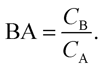
Having derived the coarse-grained elastic model of the polymer matrix and calculated the binding free energy of analytes to imprinted cavities, we now focus on characterizing MIPs with measures used in most of the literature: the binding affinity, the imprinting factor and the separation factor. A formed MIP in principle consists of heterogeneous cavities, therefore a MIP is fully characterized by a binding isotherm (Fig. 3) or an affinity distribution of cavities, e.g.ref. 17 and 40. However, it is useful to have a single number measure of MIPs. Following Tanaka25 we define the dimensionless binding affinity as the product of the concentration of cavities Ccav and the average equilibrium association constant of binding an analyte to a cavity| BAcav ≡ Ccav〈KcavA〉 | (10) |
 | (11) |
 includes corrections due to binding to non-imprinted ligands outside cavities as well as cross-cavity binding (analyte binding to two or more cavities simultaneously). If we assume that cavities are randomly distributed throughout the MIP, the correction term becomes closely related to the binding affinity for non-imprinted polymers (NIPs) described below
  . In chromatography experiments the binding affinity is expressed in terms of the retention factor of the analytes in the column. The retention factor and the equilibrium constant are monotonically related.41,42
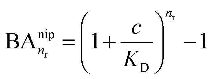
In the case of NIPs, there are no imprinted cavities and the average in (10) must be taken over a random distribution of ligands in the cross-linked matrix. The result derived in the ESI,† is
 | (12) |
 and there are nr independent receptors on the particle. This result and its derivation is conceptually similar to the theory describing multivalent particles binding to a surface.43 We observe that, for strong enough binding
  the binding affinity will scale as
  , while for weak binding
  it is approximately linear
 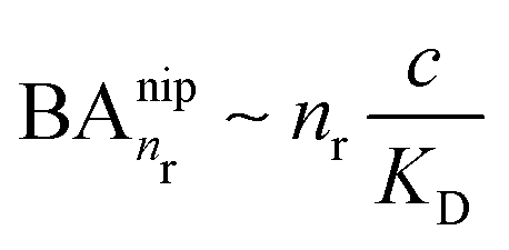 . Such scaling has been observed experimentally for collapsed and swollen hydrogels respectively.25,26
In the divalent case we can evaluate the free energy - and thus the binding affinities - analytically (eqn (4)–(8) and (12)). Assuming that imprinted cavities are randomly distributed throughout the MIP the cross-cavity term becomes equal to BAnip2, however, single bond terms need to be subtracted to prevent double counting. If the template extraction process is efficient the cavity concentration is equal to the template concentration in the imprinting phase Ccav = CT. The MIP binding affinity becomes
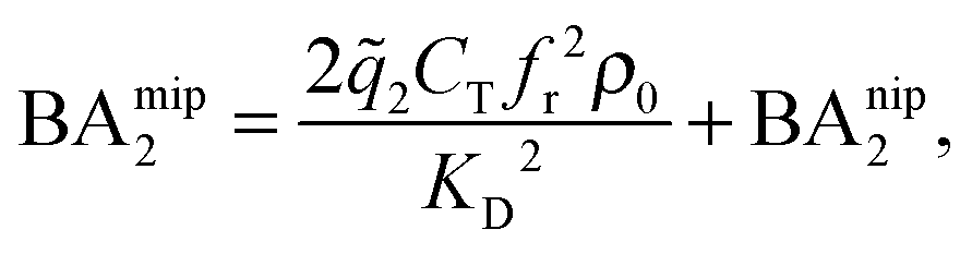 | (13) |
2 the 2 bond partition function (8) and fr, the receptor occupancy fraction (1). Heuristically, the first term on the right takes into account divalent binding to cavities, the concentration of doubly functionalized cavities being fr2CT. The second term BAnip2 takes into account all single bond states and divalent binding to all pairs of ligands that do not belong to the same cavity.
In the more general case κ > 2, BAmip can be computed by numerical simulations. From eqn (9) and (10) we observe that for low concentrations the binding affinity essentially determines the ratio of concentrations of bound analytes CB to analytes free in solution CA
 | (14) |
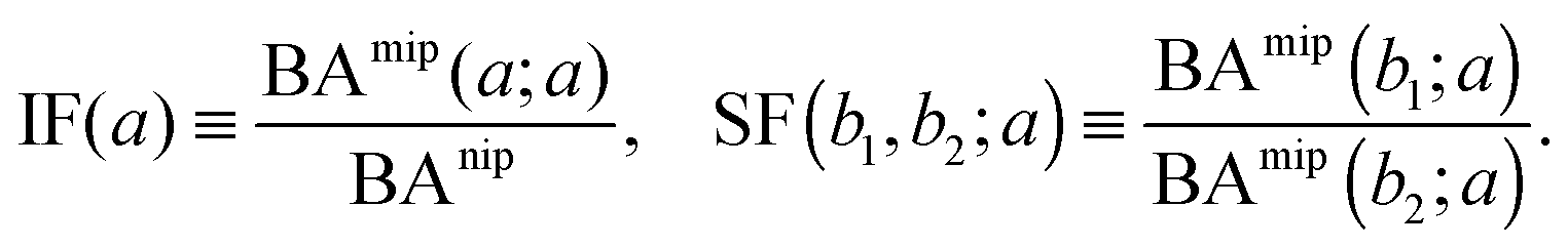
The binding affinities BAnip and BAmip can be used to evaluate two key quantities used to assess the performance of MIPs in the literature: the imprinting factor IF(a), which is the ratio of the binding affinity of a template a to a MIP and to a NIP, and the separation factor SF(b1, b2; a) measuring the ability of a MIP (imprinted by a template a) to distinguish between two different analytes b1 and b2:
 | (15) |
Design principles
We can now return to the original question: how to design the imprinting process to achieve optimal sensitivity for the desired application? To arrive at a set of rules, we have summarized the results of our model calculations into a ‘phase diagram’ that shows the regime where MIPs should function most efficiently (see Fig. 4(a)). The control parameters in the phase diagram are the stiffness of the polymer matrix and the concentration of the ligands that are incorporated into the matrix. For generality, we will again use dimensionless quantities defined above. This phase diagram suggests three general design rules for efficient molecular imprinting: | ||
Fig. 4 MIP design principles. (a) Schematic phase diagram of MIP efficiency, summarizing the design principles. The ligand concentration for which MIPs are efficient lies between the two limits:  (17) and (17) and  (16). The dashed line drawn somewhat arbitrarily at (16). The dashed line drawn somewhat arbitrarily at  separates the regions of bond selectivity and geometrical recognition. In (b) and (c) the imprinting factor calculated for divalent templates is shown as a function of separates the regions of bond selectivity and geometrical recognition. In (b) and (c) the imprinting factor calculated for divalent templates is shown as a function of  and c* at a stoichiometric ratio of ligands–receptors and c* at a stoichiometric ratio of ligands–receptors  (b), and as a function of (b), and as a function of  and c* at fixed matrix stiffness and c* at fixed matrix stiffness  (c). We have assumed an equal binding strength in the imprinting and binding stage (c). We have assumed an equal binding strength in the imprinting and binding stage  . . | ||
MIP formation
In the MIP formation process (step A on Fig. 1) the ligands should bind to the template in sufficient numbers. The binding of ligands can be calculated assuming chemical equilibrium between ligands and receptors (1), a simple rule of thumb would be that the concentration of ligands should be similar or greater than the bond dissociation constant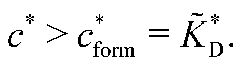 | (16) |
 , with nr the number of receptors per template. This rule, which is supported by the data in Fig. 4(c), provides an optimal tradeoff between the formation of multi-ligand cavities on the one hand, and the minimization of the number of non-imprinted ligands on the other hand. A similar empirical observation was reported in systematic experiments by Kim and Spivak,27 and also in lattice model simulations by Shimizu et al.33 If there are many different types of ligands in the solution (binding to different receptors), the rule above should be applied to each of them. The “Poor MIP formation” region
 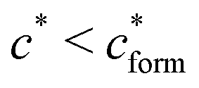 is shaded on the phase diagram in Fig. 4(a).
MIP binding
Imprinting should make a difference, i.e. templates should predominantly bind to the imprinted cavities rather then across them or to randomly distributed ligands, BAcav > BAnip. For a divalent template this results in a condition for the concentration of ligands: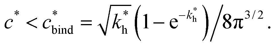 | (17) |
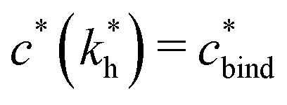 sets the upper bound for the yellow region of efficient MIPs in Fig. 4(a). Additionally, the receptor–ligand binding in step C should be strong-enough such that predominantly multiple bonds are formed (q2 > q1), which results in a similar condition:
  .
.
Cross-linking strength
The matrix stiffness plays a crucial role in the performance of MIPs, the higher the stiffness the greater the MIP selectivity, this has also been observed experimentally.44 In order to separate analytes based on the geometry (receptor patterns) – the polymer matrix has to be stiff enough:
 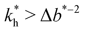 , where Δb* is a measure for the difference in geometry. For divalent particles it is the difference between the receptor distances
 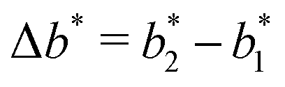 on the 2 analytes we wish to separate. For example, if the relative difference is Δb* = 0.1 then the stiffness should be greater then
  . This is marked as geometry selectivity in Fig. 4(a) and supported by calculations in Fig. 4(c). For example, the enantiomeric discrimination of analytes is only possible in the regime of geometric selectivity.
In some applications it is desirable to separate analytes according to receptor composition but not according to the geometry. For instance, if targeting a whole class of analytes with similar receptor composition but varying (or unknown) patterns (e.g., viruses with high mutation rates), geometrical selectivity is unwanted. The optimal regime of matrix stiffness for such applications is the regime of bond selectivity:  . In this regime imprinting makes a difference, however, the substrate is too flexible to allow for efficient recognition of the geometrical patterns. Hence, MIPs can only discriminate analytes with different ligand compositions.
In order to test the predictions that follow from Fig. 4(a), we compared them to the analytical results for the divalent binding model (12) and (13). To this end, we evaluated the imprinting factor IF(a) for a broad range of ligand concentrations c*, binding affinities  , and matrix elasticities
  . Fig. 4(b) shows the dependence of IF(a; a) on the matrix stiffness and on the ligand concentration at a fixed stoichiometric ratio of ligands and templates in the imprinting phase
  . Furthermore Fig. 4(c) shows the dependence of IF on the stoichiometry at fixed matrix stiffness, showing that the stoichiometric ratio is close to optimal, the optimal concentrations being
 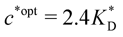 and
and 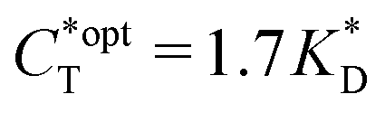 . We have assumed that the dissociation constants for individual bonds remain the same in the imprinting and binding phase
  .
.
In accordance with our tentative design rules (Fig. 4), we observe a sharp increase in the imprinting quality in the parameter region where MIPs should function optimally, i.e. for intermediate values of ligand concentrations  and stiff matrices
  .
.
Within the same parameter space we also computed the separation factor SF(a, b; a) for two slightly different analytes (b1 = a and b2 = 1.1a) on MIPs imprinted by a template with a separation a between the two receptors (Fig. 5(a)). The analyte separation is effective for matrix stiffness 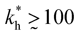 . This range can be extended if we compare analytes that are less similar. Again, the region where analyte separation is most efficient roughly coincides with the onset of geometrical recognition in Fig. 4(a).
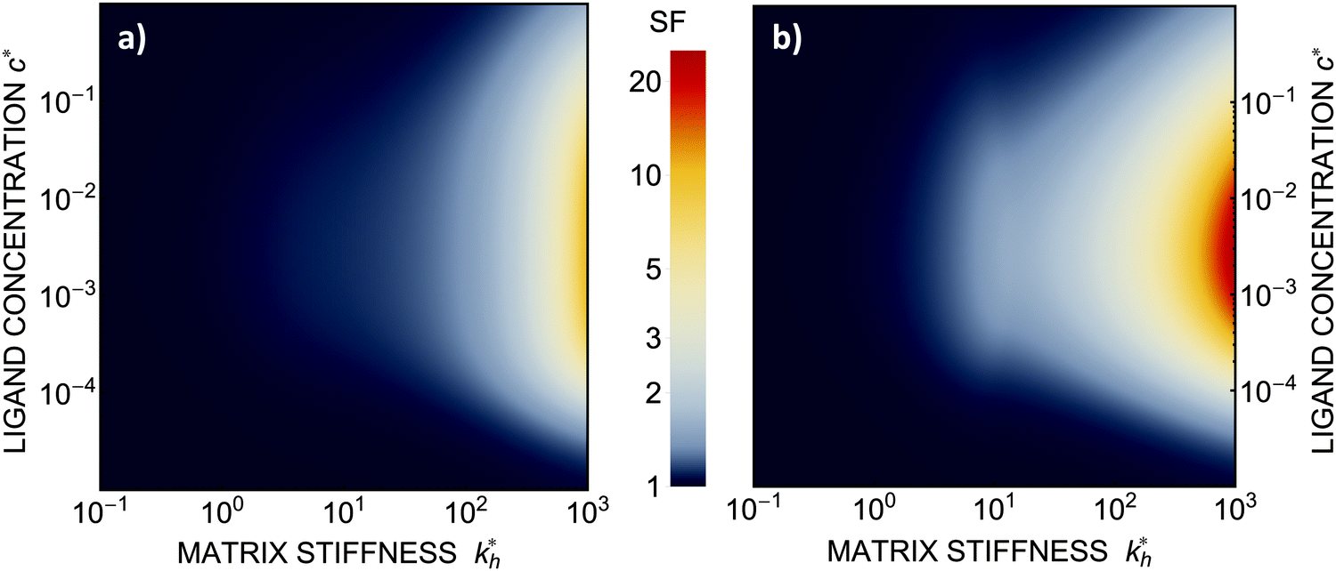 | ||
Fig. 5 (a) Separation Factor. The separation factor SF(b1, b2; a) for the imprinted template b1 = a and an analyte with slightly larger inter-receptor distance b2 = 1.1a as a function of the parameters  and c*. (b) Enhancing the selectivity. The best separation is achieved when the imprinting is slightly mismatched relative to the analyte. The separation factor SF(b1, b2; aopt) at the optimal value of the imprinted distance aopt as a function of and c*. (b) Enhancing the selectivity. The best separation is achieved when the imprinting is slightly mismatched relative to the analyte. The separation factor SF(b1, b2; aopt) at the optimal value of the imprinted distance aopt as a function of  and c*. Parameters are the same as in Fig. 4(b). and c*. Parameters are the same as in Fig. 4(b). | ||
Somewhat surprisingly, we find that the optimal separation of two analytes, say b1 = σ and b2 = 1.1σ, is not best achieved by imprinting with a template identical to the first analyte (a = b1). Rather, the separation factor SF(b1, b2; a) can be maximized by designing the cavity with an optimal imprinted distance aopt < b1. This result can be intuitively understood by noting that the binding free energy is approximately a quadratic function of the mismatch close to the minimum. If the imprinting is slightly mismatched, the binding affinity of the chosen analyte is slightly smaller, but at the same time it increases relative to the binding affinity of the other particle resulting in better separation capacity of the MIP. Fig. 5(b) displays the separation factor SF(b1, b2; aopt) for the same analytes as in Fig. 5(a) but with the template size a optimized at each point in the parameter space (see ESI†). We can clearly see an increase in the separation capability, however, the qualitative features of the phase diagram in Fig. 4(a) remain valid.
Summary
We have developed a theoretical model of molecular imprinting, which allows us to calculate the performance of imprinted polymers depending on parameters, such as polymer material properties, the choice of a template and ligand (functional monomers) concentration. We have explored various factors that determine the quality of molecular imprinting and derived a set of general design principles that can be applied to rationalize specific applications. Our predictions could be studied on a well-defined and tuneable supramolecular system, such as a solution of tetravalent DNA constructs (e.g. Holliday junctions or DNA tetrahedra45), which can bind to complementary ‘ligand’ strands that can be cross-linked into a gel.The first key observation is that the quality of imprinting depends on the concentration of ligands and templates in the imprinting phase and on the binding strength between them: the optimal imprinting is achieved with a nearly stoichiometric ratio of ligands vs. template receptors, e.g. for tri-valent templates the stoichiometric ratio of templates![[thin space (1/6-em)]](https://www.rsc.org/images/entities/char_2009.gif) :ligands should be 1:3. Additionally, initial ligand concentration should be of a similar value as the corresponding bond dissociation constant. This provides the optimal tradeoff between, on the one hand, efficient cavity formation, and on the other hand, selective re-binding of analytes to imprinted cavities.
:ligands should be 1:3. Additionally, initial ligand concentration should be of a similar value as the corresponding bond dissociation constant. This provides the optimal tradeoff between, on the one hand, efficient cavity formation, and on the other hand, selective re-binding of analytes to imprinted cavities.
The second key observation is that stiffer matrices are more selective – suggesting that it should be beneficial to make the gel as rigid as possible. Consequently, polymer gels are not a suitable matrix for efficient molecular imprinting of small molecules: when geometrical recognition is required, stiffer systems such as glassy polymers should be considered. However, the non-specific terms in the free energy – which are not explicitly considered here – will have an opposite effect upon increasing the stiffness of the matrix: slowing down of the kinetics and impeding the particles' access to the cavities. A commonly implemented solution for this problem is grinding the stiff gels in order to expose the imprinted ligands. In this case, much stiffer matrices can be used, however, the procedure inevitably reduces the imprinting quality by grinding-off a fraction of ligands in the cavities. In specific MIP systems, it is likely that the opposing thermodynamic and kinetic trends result in an application-specific optimum gel stiffness.
Moreover, when imprinting soft macromolecules such as proteins or biopolymers onto a hard matrix, the intrinsic softness of the template has a similar effect to a reduced matrix stiffness (within our coarse-grained model a soft template on a hard substrate resembles a hard template on a softer substrate). Extremely large values of the matrix stiffness  in our model are therefore unlikely to be relevant for experimental realizations. A reasonable choice of the matrix stiffness to design applications seems to be between
  , i.e. fluctuations of the ligand position relative to the size of the template between 10% and 30%. In such a case, for imprinting to work, the strength of the individual ligand–receptor bonds needs to be strong enough. Divalent templates cannot be imprinted effectively unless the bond dissociation constant is
  . This changes considerably if the templates are multivalent: in the tetravalent case imprinting can be achieved with relatively weak bonds
  , while in the hexavalent case the bonds can be extremely weak
  , which is in the realm of hydrogen bonds in aqueous solutions. This suggests that it should be possible to efficiently imprint molecules, such as proteins or drugs, onto polymers in aqueous solutions.
Acknowledgements
We gratefully acknowledge inspiring discussions with Professor Richard Zare. This work was supported by the Fundamental Research Funds for the Central Universities of P. R. China, ERC Advanced Grant 227758 (COLSTRUCTION), ITN grant 234810 (COMPPLOIDS) and by EPSRC Programme Grant EP/I001352/1. TC acknowledges support from the Herchel Smith fund.References
- B. Sellergren, B. Ekberg and K. Mosbach, J. Chromatogr., 1985, 347, 1–10 CrossRef CAS.
- L. I. Andersson and K. Mosbach, J. Chromatogr., 1990, 516, 313–322 CrossRef CAS PubMed.
- I. Dunkin, J. Lenfeld and D. Sherrington, Polymer, 1993, 34, 77–84 CrossRef CAS.
- I. A. Nicholls, O. Ramstrm and K. Mosbach, J. Chromatogr. A, 1995, 691, 349–353 CrossRef CAS.
- P. K. Dhal and F. H. Arnold, Society, 1991, 7417–7418 CAS.
- M. Polyakov, Zh. Fiz. Khim., 1931, 799–804 Search PubMed.
- H. S. Andersson, a. C. Koch-Schmidt, S. Ohlson and K. Mosbach, J. Mol. Recognit., 1996, 9, 675–682 CrossRef CAS PubMed.
- D. Todorova-Balvay, I. Stoilova, S. Gargova and M. A. Vijayalakshmi, J. Mol. Recognit., 2006, 19, 299–304 CrossRef CAS PubMed.
- L. Chen, S. Xu and J. Li, Chem. Soc. Rev., 2011, 40, 2922–2942 RSC.
- C. Alexander, H. K. S. Andersson, L. I. Andersson, R. J. Ansell, N. Kirsch, I. A. Nicholls, J. O'Mahony and M. J. Whitcombe, J. Mol. Recognit., 2006, 19, 106–180 CrossRef CAS PubMed.
- C. He, Y. Long, J. Pan, K. Li and F. Liu, J. Biochem. Biophys. Methods, 2007, 70, 133–150 CrossRef CAS PubMed ; Sample Preparation.
- M. Kempe and K. Mosbach, J. Chromatogr. A, 1995, 694, 3–13 CrossRef CAS.
- G. Wulff, Chem. Rev., 2002, 102, 1–27 CrossRef CAS PubMed.
- N. W. Turner, C. W. Jeans, K. R. Brain, C. J. Allender, V. Hlady and D. W. Britt, Biotechnol. Prog., 2006, 22, 1474–1489 CrossRef CAS PubMed.
- C. Alvarez-Lorenzo and A. Concheiro, J. Chromatogr. B: Anal. Technol. Biomed. Life Sci., 2004, 804, 231–245 CrossRef CAS PubMed.
- H. K. S. Andersson, J. G. Karlsson, S. A. Piletsky, A. C. Koch-Schmidt, K. Mosbach and I. A. Nicholls, J. Chromatogr. A, 1999, 848, 39–49 CrossRef CAS.
- G. Vlatakis, L. I. Andersson, R. Müller and K. Mosbach, Nature, 1993, 361, 645–647 CrossRef CAS PubMed.
- H. Shi, W. B. Tsai, M. D. Garrison, S. Ferrari and B. D. Ratner, Nature, 1999, 398, 593–597 CrossRef CAS PubMed.
- R. Schirhagl, E. W. Hall, I. Fuereder and R. N. Zare, Analyst, 2012, 137, 1495 RSC.
- K. Ren and R. N. Zare, ACS Nano, 2012, 6, 4314–4318 CrossRef CAS PubMed.
- S. Srebnik and O. Lev, J. Chem. Phys., 2002, 116, 10967–10972 CrossRef CAS.
- S. Srebnik, Chem. Mater., 2004, 16, 883–888 CrossRef CAS.
- L. Sarkisov and P. R. Van Tassel, J. Chem. Phys., 2005, 123, 164706 CrossRef PubMed.
- L. Sarkisov and P. R. Van Tassel, J. Phys. Chem. C, 2007, 111, 15726–15735 CAS.
- K. Ito, J. Chuang, C. Alvarez-Lorenzo, T. Watanabe, N. Ando and A. Y. Grosberg, Prog. Polym. Sci., 2003, 28, 1489–1515 CrossRef CAS.
- T. Enoki, et al. , Phys. Rev. Lett., 2000, 85, 5000–5003 CrossRef CAS PubMed.
- H. Kim and D. A. Spivak, J. Am. Chem. Soc., 2003, 125, 11269–11275 CrossRef CAS PubMed.
- C. Herdes and L. Sarkisov, Langmuir, 2009, 25, 5352–5359 CrossRef CAS PubMed.
- E. M. A. Dourado and L. Sarkisov, J. Chem. Phys., 2009, 130, 214701 CrossRef PubMed.
- E. M. A. Dourado, C. Herdes, P. R. van Tassel and L. Sarkisov, Int. J. Mol. Sci., 2011, 12, 4781–4804 CrossRef CAS PubMed.
- L. Levi, V. Raim and S. Srebnik, J. Mol. Recognit., 2011, 24, 883–891 CrossRef CAS PubMed.
- I. A. Nicholls, H. K. S. Andersson, C. Charlton, H. Henschel, B. C. G. Karlsson, J. G. Karlsson, J. O'Mahony, A. M. Rosengren, K. J. Rosengren and S. Wikman, Biosens. Bioelectron., 2009, 25, 543–552 CrossRef CAS PubMed.
- X. Wu, W. R. Carroll and K. D. Shimizu, Chem. Mater., 2008, 20, 4335–4346 CrossRef CAS.
- V. M. Krishnamurthy, L. A. Estroff and G. M. Whitesides, Fragment-based Approaches in Drug Discovery, Wiley-VCH Verlag GmbH and Co. KGaA, 2006, pp. 11–53 Search PubMed.
- L. Di Michele, B. M. Mognetti, T. Yanagishima, P. Varilly, Z. Ruff, D. Frenkel and E. Eiser, J. Am. Chem. Soc., 2014, 136, 6538–6541 CrossRef CAS PubMed , PMID: 24750023.
- P. Varilly, S. Angioletti-Uberti, B. M. Mognetti and D. Frenkel, J. Chem. Phys., 2012, 137, 094108 CrossRef PubMed.
- M. Rubinstein and R. Colby, Polymer Physics, OUP Oxford, 2003 Search PubMed.
- R. Simon, M. E. Collins and D. A. Spivak, Anal. Chim. Acta, 2007, 591, 7–16 CrossRef CAS PubMed.
- G. Ercolani and L. Schiaffino, Angew. Chem., Int. Ed., 2011, 50, 1762–1768 CrossRef CAS PubMed.
- R. J. Umpleby II, M. Bode and K. D. Shimizu, Analyst, 2000, 125, 1261–1265 RSC.
- Y. Lv, Z. Lin, T. Tan, W. Feng, P. Qin and C. Li, Sens. Actuators, B, 2008, 133, 15–23 CrossRef CAS.
- L. Wu and Y. Li, J. Mol. Recognit., 2004, 17, 567–574 CrossRef CAS PubMed.
- F. J. Martinez-Veracoechea and D. Frenkel, Proc. Natl. Acad. Sci. U. S. A., 2011, 108, 10963–10968 CrossRef CAS PubMed.
- G. Wulff, Angew. Chem., Int. Ed. Engl., 1995, 34, 1812–1832 CrossRef CAS.
- R. P. Goodman, R. M. Berry and A. J. Turberfield, Chem. Commun., 2004, 1372–1373 RSC.
Footnotes |
| † Electronic supplementary information (ESI) available. See DOI: 10.1039/c5sm02144h |
| ‡ Current institution: University of Cambridge. |
| This journal is © The Royal Society of Chemistry 2016 |