 Open Access Article
Creative Commons Attribution 3.0 Unported Licence
Reconfigurable assembly of superparamagnetic colloids confined in thermo-reversible microtubes†
Ping
Liu
 a,
Julius W. J.
de Folter
ab,
Andrei V.
Petukhov
 a and
Albert P.
Philipse
*a
aVan 't Hoff Laboratory for Physical and Colloid Chemistry, Debye Institute for Nanomaterials Science, Utrecht University, Padualaan 8, 3584CH, The Netherlands. E-mail: a.p.philipse@uu.nl; Fax: +31 302533870; Tel: +31 302533518
bUnilever Research and Development, Olivier van Noortlaan 120, 3133AT, Vlaardingen, The Netherlands
First published on 15th June 2015
Abstract
Structural transformations of superparamagnetic colloids confined within self-assembled microtubes are studied by systematically varying tube–colloid size ratios and external magnetic field directions. A magnetic field parallel to microtubes may stretch non-linear chains like zigzag chains into linear chains. Non-parallel fields induce new structures including repulsive chains of single colloids, kinked chains and repulsive dimers, which are not observed for unconfined magnetic colloids in the bulk. The formed colloidal structures are confirmed via model calculations which account for tube–colloid size ratio effects and their reconfigurability with the field direction. Furthermore, structures are formed that allow controllable switching between a helical and a non-helical state. All observed field-induced transformations in microtubes are reversible provided the microtubes are not completely filled with colloids. In addition, we demonstrate magnetic field-responsive 2D crystallization by extending control over colloidal configurations in single microtubes to multiple well-aligned microtubes.
1 Introduction
Magnetic colloidal assembly has attracted interest because of its potential applications for bioimaging, biosensing, photonic crystals, separation and drug delivery.1–8 Recently non-linear magnetic assembly was reported for new types of magnetic colloids with uneven distributions of dipoles.9–16 Examples of these colloids are asymmetric dumbbells with a magnetic “waist”, and paramagnetic colloidal peanuts; both types of non-spherical colloids may form chiral structures and zigzag chains in a homogeneous external magnetic field.9,10,16 Interestingly, colloidal spheres may also assemble to form zigzag or zipper chains in an external field, provided the magnetic dipole distribution inside the spheres is anisotropic. This magnetic anisotropy is found in Janus colloids and in spheres with off-centered magnetic cubes.11–13 Besides that, the most intriguing phase of non-linear magnetic chains – helices – can be fabricated by assembly of paramagnetic spheres in a precessing magnetic field.17The studies quoted above rely on the developments in colloid synthesis or in the design of more complicated dynamic magnetic fields to achieve non-linear magnetic assembly. There clearly remains a need for an efficient method to tune magnetic assembly. The aim of this paper is to report such a method based on the confinement of magnetizable spheres in thermo-reversible microtubes.
These microtubes self-assemble in a solution of sodium dodecyl sulfate (SDS) and β-cyclodextrin.18 Our previous work has shown that they act as facile and versatile templates in the construction of helical and other new colloidal structures by the incorporation of non-magnetic spherical and anisotropic colloids as reported in ref. 19 and 20. In comparison with our previous work we gain additional control over colloidal interactions and configurations, which are switchable via a magnetic field and its orientations. The tubes (with or without incorporated colloids) melt reversibly and re-assemble upon heating and subsequent cooling of the aqueous solution. Such a dynamic, thermo-reversible tubular confinement of colloids clearly differs from static confinements such as carbon nanotubes, rigid channels, porous membranes, optical tweezer trappings and block copolymer cylinders.21–30 The possibility of melting and forming confining microtubes at will provides an additional parameter to tune magnetic colloid structures, in addition to the orientation of an external magnetic field and the ratio of the colloid to tube diameter. It is also important that the tube and colloids can be monitored in aqueous solution with optical microscopy such that structure formation and dissolution can be imaged in situ on a single-particle level.
In this article, we investigate structure transformations of superparamagnetic colloids confined within microtubes upon the application of a magnetic field, thereby examining the interplay between magnetic interactions and tubular confinement. We systematically vary tube–colloid size ratios and directions of the external magnetic field. This strategy allows for the formation of a range of novel magnetic field-induced reconfigurable colloidal structures. A theoretical model is presented in the Appendix that accounts for experimentally observed attractive and repulsive colloidal configurations in parallel and perpendicular magnetic fields. In addition, the co-assembly of microtubes and magnetic colloidal chains, induced by applying a magnetic field before tube formation, is tracked using optical microscopy in situ. We anticipate that our study will further assist in the development of advanced functional materials relying on controlled magnetic colloidal assembly.
2 Experimental
2.1 Materials
Sodium dodecyl sulfate (SDS, 99%) was purchased from Sigma-Aldrich and was used as received. β-Cyclodextrin (β-CD) was bought from Sigma-Aldrich with a water content of 14% and was dried before use. The typical morphology of superparamagnetic colloids used in this work is illustrated in Fig. 1. The core of the colloid contains well-separated superparamagnetic nanoparticles (NPs) of typical sizes between 5 and 15 nm inside a nonmagnetic material used in the synthesis or stabilization of the NPs. The core is surrounded by a shell of non-magnetic material (here silica or polystyrene). The surface of the colloid may have functionalization specific for each application. The detailed properties of superparamagnetic colloids are given in Table 1. Dynabeads (Life Technologies) of diameter 1.05 µm were obtained in a stock concentration of 10 mg mL−1. The smaller superparamagnetic particles (SiO2-MAG-S2560, 583 nm in diameter and PS-MAG-S1984-1, 506 nm in diameter, microParticles GmbH, Germany) were supplied at a stock concentration of 25 mg mL−1 in water. In what follows the medium-size silica spheres will be denoted as “M-silica spheres” and the smallest polystyrene particles as “S-polystyrene spheres”.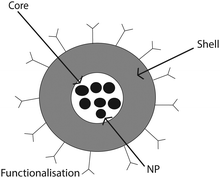 | ||
| Fig. 1 Cartoon showing the typical structure of superparamagnetic colloids composed of a core containing magnetic nano-particles and a functionalized shell. | ||
| Colloid type | Code | Diameters (nm) | Polydispersity (%) | Iron content (ferrites per g dry solid) (%) | Magnetization at 50 mT (emu g−1) | Functionality | λ |
|---|---|---|---|---|---|---|---|
| a Magnetic coupling parameter defined in eqn (2) in the Appendix. | |||||||
| Dynabeads | Dynabeads | 1050 | <3 | 37 | 12 | Carboxyl | 6939 |
| Microparticles | |||||||
| SiO2-MAG-S2560 | M-silica spheres | 583 | 2.7 | >30 | 8 | Plain | 520 |
| Microparticles | |||||||
| PS-MAG-S1984-1 | S-polystyrene spheres | 506 | 3.8 | >30 | 20 | Plain | 2157 |
The microtubes were synthesized following ref. 18. Desired amounts of SDS, β-CD and Millipore water were weighed into a vessel to give a mixture with a total concentration of SDS and β-CD of 10 wt% and a molar ratio between SDS and β-CD of 1![[thin space (1/6-em)]](https://www.rsc.org/images/entities/char_2009.gif) :
:![[thin space (1/6-em)]](https://www.rsc.org/images/entities/char_2009.gif) 2. The mixture was heated to 60 °C to obtain a transparent, isotropic solution, which was then cooled to room temperature to allow for the formation of microtubes in a viscous and turbid suspension. After staining 1 g of microtubes by 50 µL of fluorescent dye (Nile Red) solution in acetone at a concentration of 1 mg mL−1, the microtubes were imaged in aqueous solution by confocal laser scanning microscopy (CLSM) in fluorescence mode. In Fig. 2a, these uniform tubes fill up the whole field of view, exhibiting diameters of around 0.9 µm (thus termed as microtubes). Fig. 2b shows the distribution of the tube diameters as collected from fluorescence images. By fitting with a Gaussian profile, a mean tube diameter of 884 nm with a standard deviation of 183 nm (22%) is obtained.
2. The mixture was heated to 60 °C to obtain a transparent, isotropic solution, which was then cooled to room temperature to allow for the formation of microtubes in a viscous and turbid suspension. After staining 1 g of microtubes by 50 µL of fluorescent dye (Nile Red) solution in acetone at a concentration of 1 mg mL−1, the microtubes were imaged in aqueous solution by confocal laser scanning microscopy (CLSM) in fluorescence mode. In Fig. 2a, these uniform tubes fill up the whole field of view, exhibiting diameters of around 0.9 µm (thus termed as microtubes). Fig. 2b shows the distribution of the tube diameters as collected from fluorescence images. By fitting with a Gaussian profile, a mean tube diameter of 884 nm with a standard deviation of 183 nm (22%) is obtained.
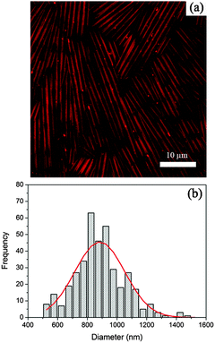 | ||
| Fig. 2 A CLSM image of microtubes (a) and histogram of the diameter distribution of the microtubes (b). | ||
2.2 Co-assembly of the superparamagnetic colloids and microtubes
An aqueous suspension of superparamagnetic colloids was centrifuged at 1800 rpm for 15 min, followed by removal of the supernatant water. Typically, 0.1 g of microtube suspension was added to the centrifuge tube to give a final microtube/colloid mixture containing 5 wt% superparamagnetic colloids. The sample was heated to 60 °C to melt the microtubes and was sonicated to disperse the particles. Then the sample was cooled to room temperature. Upon cooling, the sample was gently rotated to avoid sedimentation of the particles.2.3 In situ microscopy of magnetic field-induced colloidal assembly
The response of the magnetic colloids inside the microtubes was investigated by using a permanent magnet (NdFeB Magnet, 20 × 20 × 10 mm3, N42, 1.33 T), as illustrated in Fig. 3. The magnetic field strength upon placing the magnet 1 cm away from the sample is roughly 50 mT as measured using a Gaussmeter, and corresponding magnetizations for each type of superparamagnetic colloids are listed in Table 1. The microtube/colloid mixture was usually placed in glass capillaries (Vitrocom, 0.10 × 2.00 × 50 mm3), with both ends sealed by UV-curing epoxy glue. The magnet was moved around the sample in the sample stage plane from a parallel position to a perpendicular position, as indicated in Fig. 3. In the parallel (perpendicular) position the magnetic field direction is parallel (perpendicular) to the long axis of the microtubes. As can be seen in Fig. 2a, microtubes orient in different directions. For imaging one patch of parallel oriented microtubes was selected. The magnet was placed at the parallel position at the beginning and then moved gradually to the perpendicular position. The structure transformations were monitored using a Nikon inverted optical microscope equipped with an oil immersion 100× Nikon objective (numerical aperture is 1.4). Images were obtained with a Lumenera InfinityX CCD camera. The thermal behavior of the samples was investigated using a Linkam THMS600 microscope heating stage.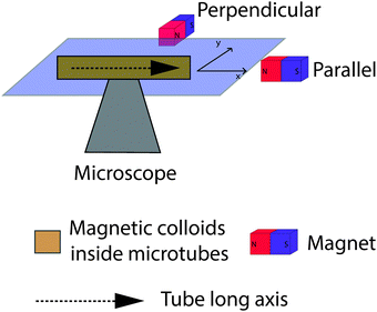 | ||
| Fig. 3 Schematic diagram of experimental setup for observation of the magnetic response of superparamagnetic colloids inside microtubes. | ||
In the setup of Fig. 3, the magnetic field may be slightly inhomogeneous with a negligible effect on structure formation as shown in the following. Approximating the field generated by the magnet as the dipole field, the strongest gradient will be observed in the longitudinal direction with B ∝ 1/r3. Thus,  can be expected, where B is the magnetic field strength in Tesla and r represents the distance between the observed region and the magnet. For instance, the difference in percentage of the magnetic field in one typical image region of 50 µm by 50 µm when placing a magnet 1 cm away from the sample is around 1.5%. It indicates that the effect of gradient is very small, so it will have little effect on the observed structures in an external magnetic field.
3 Results and discussion
3.1 Magnetic response of tube-confined chain configurations
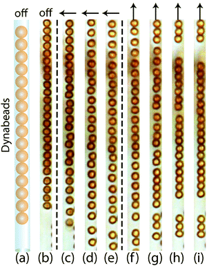
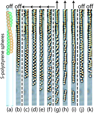
Since there is no exchange of colloids after completing colloid-in-tube assembly, each microtube can be regarded as an independent subsystem with its own colloidal chain configuration. Single chains, zigzag chains, zipper chains and helical chains can be obtained by tuning tube–colloid size ratios, similar to those observed in ref. 19. More importantly, these structures are dynamic, which allows us to further tune them using an external magnetic field. In what follows, a “parallel field” always denotes a magnetic field that is parallel to the long axis of the microtube. Similarly, a “perpendicular field” is always oriented perpendicular to the long axis of the tube, see also Fig. 3. The effect of a perpendicular field on tube-confined, fully magnetized spheres is calculated in the Appendix; these calculations will be used later to underpin observed structural transitions.Once a parallel magnetic field is applied by rotating the former perpendicular magnetic field, the dipole moments of superparamagnetic colloids all change direction and align with the long axis of the microtubes. Hence, the interactions between the colloids become attractive, with a maximum attraction of −2λ referring to Fig. 14 in Appendix. It is observed that the neighbouring colloids form close packed chains, as shown in Fig. 4(f–i). It is worth noting that these transformation images are taken at intervals of seconds which are indicated in the figure caption. The transition agrees with the model in the Appendix for a tube–colloid diameter ratio close to unity. The magnetic response of colloids of single chains in multiple well-aligned neighbouring tubes will be discussed in Section 3.3.
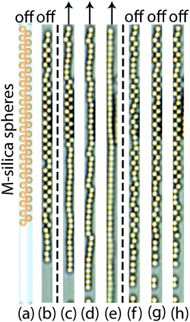
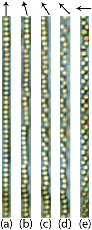
After the zigzag chains are stretched into single chains (Fig. 6a) by a parallel field, the magnetic response of the stretched single chain upon rotating the field from parallel to perpendicular step by step is illustrated in Fig. 6(b–d). In Fig. 6b, single chains become kinked chains when slowly rotating the magnetic field away from the parallel position. Upon further rotation, the kinked pieces become even shorter, as indicated in Fig. 6(c and d), and end up as tilted dimers under a perpendicular magnetic field (Fig. 6e).
Rotations of the dipole moments of superparamagnetic colloids are not restricted and their preferential orientations are always parallel to the external magnetic field. Once zigzag chains are imposed upon by a parallel magnetic field, all the dipole moments in zigzag chains align along microtubes. Note that the angle between each dipole and the line connecting adjacent dipoles is appropriate to allow superparamagnetic colloids in zigzag configurations to become attractive in the parallel field as indicated in Fig. 14 in the Appendix. The size ratio between M-silica spheres and microtubes is around 1.52, which corresponds to an attractive interaction of −1.19λ in our theoretical description. Therefore, zigzag chains are able to be stretched into single chains with head-to-tail attractive colloids. Upon slowly rotating parallel magnetic field to the perpendicular direction, attractive chains of colloids cannot rotate as a whole due to the confinement imposed by the microtubes. Instead they transform into kinked chains. The length of kinked pieces is controlled by magnetic directions. In a perpendicular field, they reduce to tilted dimers. Configurations may vary depending on the colloid concentration per microtube.
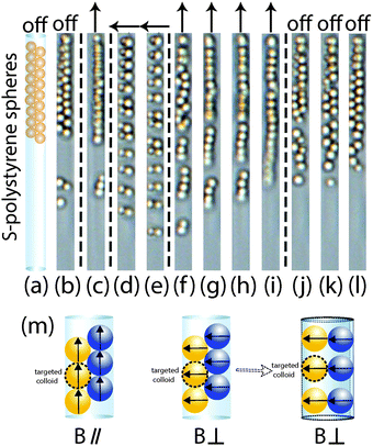
In a zigzag chain, every colloid has only two contact colloids, and the interactions between these colloids are attractive in a parallel field. However, in a zipper chain, there are four contact colloids for one targeted colloid (Fig. 7m). In a parallel field, two of these contact colloids on the same side of targeted colloid impose strongest attractive interactions of −2λ, which is similar to single chains of Dynabeads in a parallel magnetic field. The other two adjacent colloids (indicated by blue color in Fig. 7m) exert a weaker attraction force of −0.31λ to the targeted colloid, which is marked for S-polystyrene spheres in a parallel field in Fig. 14. The weaker attraction force cannot overcome the strongest attraction; as a result, the zipper chains cannot be stretched into single chains in a parallel field.
Starting from the zipper configuration, we can employ a magnetic field to obtain new assembled structures like repulsive dimers upon application of a perpendicular field. Fig. 7(d and e) shows these adjacent colloids re-assemble into dimers in a perpendicular field. As shown in the Appendix, for tube–colloid size ratios larger than 1.58, the interactions between two contact colloids become attractive, which corresponds to an attraction of −0.67λ for S-polystyrene spheres in a perpendicular field (see Fig. 13 and 14). Fig. 7m also illustrates the dipole directions of four contact colloids with targeted colloids in a perdicular field. The two colloids on the same side of targeted colloids have the strongest repulsive interactions of λ, which is similar to single chains of Dynabeads in a perpendicular magnetic field; the other two contact colloids impose an attaction interaction on the targeted colloid. The outcomes of both repulsive and attraction interactions lead to the formation of repulsive dimers in microtubes. Because molecular SDS/2β-CD microtubes form a soft confinement template, they could apparently be deformed somewhat to allow for the formation of a nearly perpendicular orientation of the dimers in the microtubes. When applying a parallel magnetic field to these repulsive dimers, colloids assemble into single chain configurations. This is because repulsive dimers have more space than colloids in the initial zipper chains, and they can re-orient themselves with confinement to keep their dipole moment along the magnetic field. The head-to-tail dipole configuration is energetically favorable. However, the configuration of side-by-side two parallel dipoles is energetically unfavorable.32 After removal of the magnetic field, colloids are subjected to thermal motion and re-assembled back to the zipper chain configurations.
For S-polystyrene spheres, the tube–colloid size ratio is around 1.75, typical chain configurations are zipper chains. However, due to polydispersity in diameters of S-polystyrene spheres (3.8%) and microtubes (22%), the tube–colloid size ratio has a quite widely propagating polydispersity which results in a range of 1.3–2.2. As simulated by Pickett et al.31 for close-packed cylindrically confined hard spheres, when the tube–colloid size ratio is larger than 1.866, helical chains could be obtained. Although the helical chains are not dominant configurations for S-polystyrene spheres, in this work we mainly focus on colloids in the subsystem of only one microtube. Therefore we could use helical chains made of S-polystyrene spheres to study the effect of size ratio on the magnetic response of different chain configurations.
Upon the application of a perpendicular magnetic field, helical chains melt in time, as indicated in Fig. 8(c–f). Colloids at the end of the chain where they have more free space start to detach first, resulting in the zigzag configuration shown in Fig. 8(c and d). Sequentially, the melting extends to the other end of the chain (f). Upon changing the direction of the applied magnetic field from perpendicular to parallel, a single chain of attractively interacting colloids is obtained as shown in Fig. 8i. After removal of the magnetic field, the colloids relax and re-assemble into a helical configuration.
Fig. 8a shows the schematic image of a helical chain in zero field. In this case the dipole moments of magnetic colloids cannot be regarded in the same plane. So once a magnetic field is applied, the dipole interactions become more complicated than that for the planar arrangements discussed above such as single chains, zigzag chains and zipper chains. In the Appendix, we only take planar arrangements into account. For 3D structures, such as helices a more complicated model is needed, which is the subject of future work.
3.2 Comparison of the magnetic behavior of magnetic colloids in microtubes and in the bulk
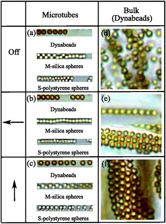
In the previous Section 3.1, the focus was on magnetized spheres confined in tubes. Now we will compare these confined spheres to spheres free in solution. Fig. 9 compares field-induced structures of confined magnetic spheres (panels a–c) to structures formed by Dynabeads in an unconfined bulk solution (panels d–f).When free, unconfined spheres are magnetized, they form chains that weakly attract each other33 such that they eventually form sheets34,35 (Fig. 9e). This sheet formation is prohibited by tube-confinement of chains because the already weak interchain attraction is further reduced by the tubes. This situation resembles that of dipolar magnetite chains incorporated in magnetotactic bacteria, an incorporation that also prohibits aggregation of magnetic chains, as discussed in detail in ref. 33. Here, we also investigate the effect of magnetic field directions: magnetic chains and sheets rotate as a whole to keep the head-to-tail configuration, as can be seen in Fig. 9(e and f) for unconfined Dynabeads. However, confined magnetic chains cannot follow the magnetic field rotation because the confining rigid tubes form a densely packed highly viscous structure. This shows that microtubes are rigid and that they cannot be reoriented. The magnetic response of colloids in bulk matches that of the other studies in the literature. Faraudo et al.36,37 have recently reported that the superparamagnetic particles can form single chains in a very short time after the application of the gradient magnetic field. When the magnetic field is retained for a longer time, magnetic chains drift until they come across another chain to form bundles. If the direction of the magnetic field is changed, these magnetic bundles rotate to keep the head-to-tail configuration parallel to the field.
3.3 Magnetic response of colloids confined in parallel neighbouring tubes
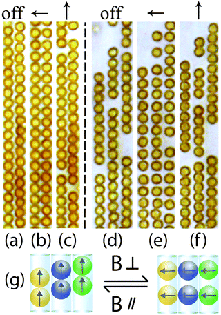
So far we have only considered colloid confinement in a single tube; we now explore the interesting structures in neighbouring parallel tubes in which spheres from different tubes have a strong dipole interaction. The magnetic responses of Dynabeads in two and three neighbouring chains are shown in Fig. 10(a–c) and (d–f), respectively. In the absence of a magnetic field, Dynabeads from different chains form a triangular lattice in the 2D plane Fig. 10(a and d). When applying a perpendicular magnetic field to microtubes, Dynabeads in one microtube repel each other, as discussed in 3.1. However, the interactions between colloids from different microtubes are attractive. The combination of these effects results in a square lattice arrangement of colloids in a 2D plane (Fig. 10(b and e)). In other words, a square lattice is more stable in a perpendicular field. In a unit of square lattice, colloids from the same microtubes repel each other, but the colloids from different microtubes attract. Both repulsive and attractive forces stabilize the square lattice. The co-existence of repulsive and attractive interactions is ascribed to the confinement effect from the microtubes. The spacing between repulsive colloids may vary depending on the particle concentration in the microtubes. At the same time, these square lattices can reversibly transform back to triangular lattices by tuning the direction of the magnetic field from perpendicular to parallel (Fig. 10(c and f)), as illustrated in Fig. 10g. In this way parallel attractions are optimized while lateral repulsions are reduced.3.4 Magnetic response of chains with different volume fractions of superparamagnetic colloids inside microtubes
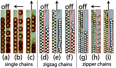
The above cases have been studied for the case in which the subsystems of microtubes are not completely filled with colloids. So these have space available for self-diffusion and respond to an applied magnetic field. However, when microtubes are completely filled with colloids, these colloid configurations cannot make any detectable changes. The differences of magnetic response of colloids in different microtubes with various volume fractions of colloids are shown in Fig. 11. The colloids in a single, zigzag and zipper chain configuration that cannot respond to a magnetic field due to a high volume fraction of colloids in the microtubes are shown in the left parts in Fig. 11(a–i). Colloidal configurations that can respond to a magnetic field are shown in the right parts and are typically found in microtubes with a lower colloid concentration. For the magnetic colloids in completely filled microtubes, although the induced magnetic dipole interactions are the same, they cannot make any movement.32 This is simply because the particle concentration is too high in the same microtube so that the particles do not have space to move. For lower particle concentration, colloids from single chains (Fig. 11b) and zipper chains (Fig. 11h) form repulsive singles and dimers in a perpendicular field. Colloids in zigzag chains (Fig. 11e) become attractive and form single chains in a parallel magnetic field.3.5 Application of magnetic field before microtubes formation
Until now we have studied the assembled structures inside microtubes upon application of a magnetic field. Let us now discuss how the system responds to a thermal treatment since the microtubes are temperature-sensitive. It is possible to apply a magnetic field to a mixture of particles, SDS and β-CD before the formation of microtubes. We start with the structures of the Dynabeads inside the microtubes at room temperature and with the magnetic field along the long axis of the microtubes in the optical microscopy image domain (Fig. 12A). As the temperature is increased, the tubes start to melt and some of the Dynabeads are released from the microtubes. Because of the application of the magnetic field, the colloids form chains after melting of the microtubes, as shown in Fig. 12B. At 45 °C, the microtubes disappear and the solution becomes isotropic, during which the viscosity decreases dramatically from a highly viscous state (can be distinguished by the naked eye) to that of a low-viscosity fluid like water. In Fig. 12(C and D), it can be seen clearly that as the Dynabeads chains are kept at the high temperature for a longer time, the length of the Dynabead chains can be extended further. At that point, the sample is cooled down at the highest speed (5 °C min−1); then the long Dynabeads chains fall apart into shorter pieces which could still be incorporated into the microtubes. Finally the structure ends up with relatively long chains in the microtubes than in the starting state, see Fig. 12F.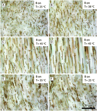 | ||
| Fig. 12 Optical microscopy images of melting and cooling processes of magnetic colloids (Dynabeads) inside the microtubes in a magnetic field parallel to the microtubes. | ||
The magnetic behavior of Dynabeads before microtube formation is the same as of superparamagnetic colloids suspensions under magnetic fields. Here we tried to cool down the system before the formation of bundles of Dynabeads, even though the bundles of two chains could also be seen in Fig. 12D. For more details, see the movie directly recorded using optical microscopy (see Movie 1 in the ESI†). Note that long chains cannot be incorporated into the microtubes. Instead, they break apart into smaller chains due to the self-assembly force exerted by the formation of microtubes during the cooling process.
4 Conclusions
We have studied the reversible magnetic response of superparamagnetic colloids confined in self-assembled microtubes and identified new morphologies including zigzag chains, zipper chains, helical chains, field-induced kinked chains and repulsive dimers. Straight chains can be transformed into a repulsive chain of separate colloids upon application of a perpendicular magnetic field. Zigzag chains can be stretched directly by a parallel magnetic field into linear chain configurations, which is not the case for zipper and helical chains. The latter can only be stretched in a parallel field after applying a perpendicular field. Stretched single chains may form kinked chains in a rotating magnetic field. In a perpendicular field, these chains may transform into repulsive dimers, as is also the case for zipper chains. All observed field-induced transformations in confinement clearly differ from those in a bulk suspension of the magnetizable colloids. To have tunable structures, the microtubes should not be completely filled with magnetic colloids. The colloidal configurations observed under the application of a parallel or perpendicular magnetic field are underpinned by model calculations which confirm that tube–colloid size ratio strongly influences the magnetic interactions between colloids in 1D confinement.We have extended a one microtube system to a multiple well-aligned microtubes system to achieve magnetic field tunable 2D crystallization. We have also exploited the thermo-reversibility of microtube self-assembly to steer the assembly of magnetic colloidal chains: when applying a magnetic field before formation of microtubes, the assembly of microtubes tears apart magnetic chains into shorter fragments to incorporate them inside, which is studied in situ under optical microscopy.
In this study we have demonstrated additional control over colloidal structures using facile, reconfigurable self-assembly. This is achieved in a thermo-reversible matrix of confining microtubes self-organized from readily available molecular species. Colloidal configurations can be tuned by colloid concentration, tube–colloid size ratio and the application of magnetic fields in different directions. The combination of confinement and the magnetic field response of the colloids results in novel structures that can deliberately be switched ‘on’ and ‘off’. For instance, magnetic spheres may assemble into reversible helical structures that can be activated or deactivated to a non-helical state depending on the application of a magnetic field. Externally controlled formation and disruption of targeted colloidal configurations may open new directions for data storage applications.
Appendix
Effect of the tube–colloid size ratio on magnetic interactions of tube-confined superparamagnetic spheres
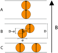
Consider two magnetisable spheres with diameter σ that are permanently magnetized by an external magnetic field![[B with combining right harpoon above (vector)]](https://www.rsc.org/images/entities/i_char_0042_20d1.gif) ; the spheres are confined in a tube with diameter D and the field is perpendicular to the tube (Fig. 13). We ask for the interaction energy for the two spheres at contact, as a function of the tube diameter D or – more precisely – as a function of the ratio D/σ.
; the spheres are confined in a tube with diameter D and the field is perpendicular to the tube (Fig. 13). We ask for the interaction energy for the two spheres at contact, as a function of the tube diameter D or – more precisely – as a function of the ratio D/σ.
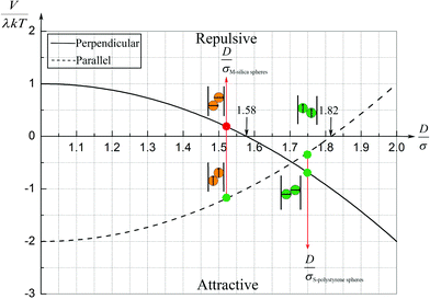 | ||
| Fig. 14 Sketch of the magnetic contact interaction from eqn (5) and (11); the interaction is zero at D/σ = 1.58 and 1.82. In a perpendicular field (solid line), at larger D/σ, the spheres attract whereas below this zero point the spheres repel. In a parallel field (dashed line), at larger D/σ, the spheres repel whereas below this zero point the spheres attract. | ||
The interaction energy between two permanent dipoles with equal magnetic moments μ at a center-to-center distance r is
 | (1) |
 | (2) |
![[small mu, Greek, circumflex]](https://www.rsc.org/images/entities/i_char_e0b3.gif) 1 and
1 and ![[small mu, Greek, circumflex]](https://www.rsc.org/images/entities/i_char_e0b3.gif) 2;
2; ![[r with combining circumflex]](https://www.rsc.org/images/entities/i_char_0072_0302.gif) is the unit vector of the center-to-center vector
is the unit vector of the center-to-center vector ![[r with combining right harpoon above (vector)]](https://www.rsc.org/images/entities/i_char_0072_20d1.gif) . For magnetic moments that are always parallel as in Fig. 13, the interaction (1) simplifies to
. For magnetic moments that are always parallel as in Fig. 13, the interaction (1) simplifies to | (3) |
![[small mu, Greek, vector]](https://www.rsc.org/images/entities/i_char_e0e9.gif) and
and ![[r with combining right harpoon above (vector)]](https://www.rsc.org/images/entities/i_char_0072_20d1.gif) (Fig. 13). Upon inspection of Fig. 13B we realize that
(Fig. 13). Upon inspection of Fig. 13B we realize that | (4) |
 | (5) |
 | (6) |
 | (7) |
 | (8) |
 | (9) |
The smaller magnetic spheres used here have diameters of 506 nm (S-polystyrene spheres) and 583 nm (M-silica spheres); for a tube with D = 884 nm (see Fig. 2) this implies D/σ = 1.75 and D/σ = 1.52. The contact interactions in a perpendicular field are
In a parallel field, the magnetic interaction energy can be examined in the same manner as for a perpendicular field. We only need to change the angle θ between ![[small mu, Greek, vector]](https://www.rsc.org/images/entities/i_char_e0e9.gif) and
and ![[r with combining right harpoon above (vector)]](https://www.rsc.org/images/entities/i_char_0072_20d1.gif) into 90° − θ. Then the eqn (3) and (5) can be rewritten as
into 90° − θ. Then the eqn (3) and (5) can be rewritten as
 | (10) |
 | (11) |
Fig. 14 also shows the sketch of the magnetic contact energy in a parallel field, indicated by a dashed line. From (11) we find the maximal attraction
 | (12) |
 | (13) |
 | (14) |
Acknowledgements
P. L. is supported by a scholarship under State Scholarship Fund (File No. 201206920001) from the Chinese government.References
- R. M. Erb, H. S. Son, B. Samanta, V. M. Rotello and B. B. Yellen, Nature, 2009, 457, 999–1002 CrossRef CAS PubMed.
- G. Friedman and B. Yellen, Curr. Opin. Colloid Interface Sci., 2005, 10, 158–166 CrossRef CAS PubMed.
- D. Jańczewski, Y. Zhang, G. K. Das, D. K. Yi, P. Padmanabhan, K. K. Bhakoo, T. T. Y. Tan and S. T. Selvan, Microsc. Res. Tech., 2011, 74, 563–576 CrossRef PubMed.
- M. Wang, L. He, S. Zorba and Y. Yin, Nano Lett., 2014, 14, 3966–3971 CrossRef CAS PubMed.
- J. Ge, Y. Hu and Y. Yin, Angew. Chem., Int. Ed., 2007, 119, 7572–7575 CrossRef PubMed.
- O. D. Velev and E. W. Kaler, Langmuir, 1999, 15, 3693–3698 CrossRef CAS.
- O. D. Velev and S. Gupta, Adv. Mater., 2009, 21, 1897–1905 CrossRef CAS PubMed.
- A. Pal, V. Malik, L. He, B. H. Erné, Y. Yin, W. K. Kegel and A. V. Petukhov, Angew. Chem., Int. Ed., 2015, 54, 1803–1807 CrossRef CAS PubMed.
- D. Zerrouki, J. Baudry, D. Pine, P. Chaikin and J. Bibette, Nature, 2008, 455, 380–382 CrossRef CAS PubMed.
- S. H. Lee and C. M. Liddell, Small, 2009, 5, 1957–1962 CrossRef CAS PubMed.
- J. Yan, M. Bloom, S. C. Bae, E. Luijten and S. Granick, Nature, 2012, 491, 578–581 CrossRef CAS PubMed.
- S. K. Smoukov, S. Gangwal, M. Marquez and O. D. Velev, Soft Matter, 2009, 5, 1285–1292 RSC.
- S. Sacanna, L. Rossi and D. J. Pine, J. Am. Chem. Soc., 2012, 134, 6112–6115 CrossRef CAS PubMed.
- J. Ge, Y. Hu, T. Zhang and Y. Yin, J. Am. Chem. Soc., 2007, 129, 8974–8975 CrossRef CAS PubMed.
- L. He, Y. Hu, H. Kim, J. Ge, S. Kwon and Y. Yin, Nano Lett., 2010, 10, 4708–4714 CrossRef CAS PubMed.
- G. Singh, H. Chan, A. Baskin, E. Gelman, N. Repnin, P. Král and R. Klajn, Science, 2014, 345, 1149–1153 CrossRef CAS PubMed.
- N. Casic, N. Quintero, R. Alvarez-Nodarse, F. G. Mertens, L. Jibuti, W. Zimmermann and T. M. Fischer, Phys. Rev. Lett., 2013, 110, 168302 CrossRef.
- L. Jiang, Y. Peng, Y. Yan, M. Deng, Y. Wang and J. Huang, Soft Matter, 2010, 6, 1731–1736 RSC.
- L. Jiang, J. W. J. de Folter, J. Huang, A. P. Philipse, W. K. Kegel and A. V. Petukhov, Angew. Chem., Int. Ed., 2013, 52, 3364–3368 CrossRef CAS PubMed.
- J. W. J. de Folter, P. Liu, L. Jiang, A. Kuijk, H. E. Bakker, A. Imhof, A. van Blaaderen, J. Huang, W. K. Kegel, A. P. Philipse and A. V. Petukhov, Part. Part. Syst. Charact., 2015, 32, 313–320 CrossRef CAS PubMed.
- Y. Yin and Y. Xia, J. Am. Chem. Soc., 2003, 125, 2048–2049 CrossRef CAS PubMed.
- B. Gates, Y. Yin and Y. Xia, Chem. Mater., 1999, 11, 2827–2836 CrossRef CAS.
- J. H. Moon, S. Kim, G.-R. Yi, Y.-H. Lee and S.-M. Yang, Langmuir, 2004, 20, 2033–2035 CrossRef CAS.
- A. N. Khlobystov, D. A. Britz, A. Ardavan and G. A. D. Briggs, Phys. Rev. Lett., 2004, 92, 245507 CrossRef.
- I. Kretzschmar and J. H. K. Song, Curr. Opin. Colloid Interface Sci., 2011, 16, 84–95 CrossRef CAS PubMed.
- G.-R. Yi, T. Thorsen, V. N. Manoharan, M.-J. Hwang, S.-J. Jeon, D. J. Pine, S. R. Quake and S.-M. Yang, Adv. Mater., 2003, 15, 1300–1304 CrossRef CAS PubMed.
- T. O. E. Skinner, H. M. Martin, D. G. A. L. Aarts and R. P. A. Dullens, Soft Matter, 2013, 9, 10586–10591 RSC.
- A. V. Straube, A. A. Louis, J. Baumgartl, C. Bechinger and R. P. A. Dullens, EPL, 2011, 94, 48008 CrossRef.
- A. V. Straube, R. P. A. Dullens, L. Schimansky-Geier and A. A. Louis, J. Chem. Phys., 2013, 139, 134908 CrossRef PubMed.
- S. Sanwaria, A. Horechyy, D. Wolf, C.-Y. Chu, H.-L. Chen, P. Formanek, M. Stamm, R. Srivastava and B. Nandan, Angew. Chem., Int. Ed., 2014, 53, 9090–9093 CrossRef CAS PubMed.
- G. T. Pickett, M. Gross and H. Okuyama, Phys. Rev. Lett., 2000, 85, 3652 CrossRef CAS.
- R. S. Paranjpe and H. G. Elrod, J. Appl. Phys., 1986, 60, 418–422 CrossRef PubMed.
- A. P. Philipse and D. Maas, Langmuir, 2002, 18, 9977–9984 CrossRef CAS.
- V. Malik, A. V. Petukhov, L. He, Y. Yin and M. Schmidt, Langmuir, 2012, 28, 14777–14783 CrossRef CAS PubMed.
- M. Klokkenburg, B. H. Erné, J. D. Meeldijk, A. Wiedenmann, A. V. Petukhov, R. P. A. Dullens and A. P. Philipse, Phys. Rev. Lett., 2006, 97, 185702 CrossRef.
- J. Faraudo and J. Camacho, Colloid Polym. Sci., 2010, 288, 207–215 CAS.
- J. Faraudo, J. S. Andreu and J. Camacho, Soft Matter, 2013, 9, 6654–6664 RSC.
Footnote |
| † Electronic supplementary information (ESI) available: 1 movie showing a thermo-reversible process in a magnetic field for superparamagnetic colloids inside microtubes. See DOI: 10.1039/c5sm01035g |
| This journal is © The Royal Society of Chemistry 2015 |

