
 Open Access Article
 This Open Access Article is licensed under a Creative Commons Attribution-Non Commercial 3.0 Unported Licence
Hyperelastic models for hydration of cellular tissue†
R. G. M.
van der Sman
Agrotechnology and Food Sciences Group, Wageningen University & Research, the Netherlands. E-mail: ruud.vandersman@wur.nl
First published on 11th August 2015
Abstract
In this paper we present hyperelastic models for swelling elastic shells, due to pressurization of the internal cavity. These shells serve as model systems for cells having cell walls, as can be found in bacteria, plants and fungi. The pressurized internal cavity represents the cell vacuole with intact membrane at a certain turgor pressure, and the elastic shell represents the hydrated cell wall. At pressurization the elastic shell undergoes inhomogeneous deformation. Its deformation is governed by a strain energy function. Using the scaling law of Cloizeaux for the osmotic pressure, we obtain approximate analytical expressions of the cell volume versus turgor pressure – which are quite comparable to numerical solutions of the problem. Subsequently, we have simulated the swelling of shells – where the cell wall material is embedded with microfibrils, leading to strain hardening and anisotropic cell expansion. The purpose of our investigations is to elucidate the contribution of cell membrane integrity and turgor to the water holding capacity (hydration) of plant foods. We conclude with a discussion of the impact of this work on the hydration of food material, and other fields like plant science and the soft matter physics of responsive gels.
1 Introduction
Understanding of the hydration of cellular tissue is of importance in various fields of science. In plant science this subject is named water relations, which governs phenomena like water transport, water stress, growth and mechanical stability.1 In food science the subject is named water holding capacity, which governs sensorial traits like juiciness and hardness.2,3 In biotechnological fermentations the role of water in cells is important, because many relevant biochemical processes require that the organisms is in the state of full turgor.4In the recent years we have been investigating theories explaining the water holding capacity (WHC) of foods. Before our investigations, there has hardly been any understanding on the physics governing the water holding of foods.5 Moreover, there is no well-defined experimental method to measure it. Consequently, WHC is still regarded as an ill-defined concept. We have defined the WHC as the amount of moisture retained by a food subject to a defined mechanical load.6–8 We have drawn an analogy with polymer gels, and we have shown that the classical Flory–Rehner theory,9 describing the swelling of polymer gels, applies equally to food materials.10,11 However, for plant food materials having cellular tissue, the theory is incomplete, as it only applies to gel-like parts of the cellular tissue: the cell wall material and cytoplasm.
In this paper we extend our theory to account for the interaction between cell wall, and the osmotic pressure generated by solutes in vacuole and the integrity of the cell membrane. The osmotic pressure induces uptake of water, inflates the cell volume and deforms the cell wall. The cell wall is an elastic network of biopolymers, and its deformation generates the turgor pressure, which balances the osmotic pressure in homeostasis.1
While in food science the effect of turgor pressure is hardly regarded in the water holding capacity, the reverse holds for plant science. In the science of water relations of plants the main focus is on turgor,1 but the possible water retention by cell wall material is largely ignored.12–15 The contribution of turgor pressure to WHC is quite evident if the cell membrane is damaged via freezing. This loss of turgor leads to drip loss upon thawing of the frozen tissue.16,17 The contribution of the cell wall to the water retention in plants is not directly evident, and consequently it is some debate in literature.18 Hence, below we discuss this point in more detail.
In plant science there are a few studies, which do take into account the water retention of the cell wall.19 Here one distinguishes water in the symplast and the apoplast separately, which are also named free and bound water. These studies have found that in leafy vegetables like spinach and lettuce, the relative amount of water (RWC) in the apoplast is in the range of 10–40%.20 Similar values are found for leaves of various grain cultivars.15,18 Under conditions where the cell wall is less stretched as under drought stress conditions, the relative contribution of water retention by the apoplast becomes more significant.18,21 In cactus the apoplast water is even reaching 50%, and thus helps considerably in its survival under dry conditions.15 Yet for other foods like berry and citrus fruits, which are meant to be juicy, the RWC is estimated to be 5% at maxium. Their juiciness is thought to be controlled by the relative cell wall thickness.22 But, in apples one has found RWC = 10%.23
Most models in plant science on mechanical behaviour of cells consider the cell wall only as a thin elastic shell.24 It is recognized that cell wall thickness and initial radial stretch of the inflated cell are difficult to determine. Also, mature fruits cells have undergone large expansion, and consequently the cell wall are largely stretched.25,26 The debate is not made easy by the inconsistency between experimental methods to determine RWC. While one method determines bound water by the biopolymer matrix after drying, the other method extrapolates it from turgor pressure/cell volume curve.18 This inconsistency is probably caused by the fact that the bound water measurement also includes water bound to the cytoplasm. Furthermore, it is assumed that amount of bound water is independent of the inflation of the cell (i.e. stretching of the cell wall material). Hence, the resolution of our question in how far turgor pressure influences water retention in foods, will also help the resolution of the debated question in plant science in how far water in apoplast contribute to water retention in plants.
To resolve these questions, we will perform a theoretical analysis of the contributions of both the turgor and the hydrated cell wall to the total water holding capacity of cellular tissue. The cell wall material will be viewed as a hydrogel, which undergoes large deformation to reach full turgor. Via the deformation the hydration state of the cell wall will change. Because of the large deformation of the cell wall, it is required to describe that with hyperelastic models.27–29 These kinds of models has been applied earlier to cell walls,30–34 but their swelling properties have been disregarded.
Only recently models have been developed taking into account of the interaction between swelling and large deformation of gels in the fields of responsive hydrogels,35–37 controlled release,38–41 and swelling induced cavitation in gels.42–44 In these models the mixing free energy has been described with Flory–Huggins as in Flory–Rehner theory. This theory can easily be extended for polyelectrolyte gels, via inclusion of an extra term in the free energy describing the electrostatic interactions.45 These models also bear similarity with models considering biological elastic media which grow due to synthesis of polymers.46–48 Swelling rubbers is often taken as a model for the growth of biological tissue.49–51
In these hyperelastic models the cellular structure can be represented by a (spherical or cylindrical) shell of hydrogel material, surrounding a liquid-like region having an elevated internal pressure.30–34 Because the similarity of cell tissue with liquid-filled foams,24,52 we assume that cell models like developed by Amon and Denson can readily applied to represent the behaviour cell tissue.53 Like in foams, the cells in tissues have a hexagonal shape – but which can be approximated by spherical shells having stress free boundary conditions at the outer boundary.54 More advanced unit cell models accounting for the hexagonal shape are developed.55 Further, in some cases like mature fruit the cells do have spherical shape. For these foods, cell wall hydration during ripening has been observed.26
The pressure within the shell represents the osmotic pressure generated by the solutes in the vacuole. To describe the swelling behaviour of the cell wall, we require a description of the osmotic pressure of the hydrogel shell (which is different from the osmotic pressure inside the cell). For the osmotic pressure we will make use of the scaling law of Cloizeaux,56,57 which we have recently shown to hold for a wide range of biopolymer networks.58 The scaling law renders similar predictions as the Flory–Rehner theory, but it is more usefull in this case, because it has a compact formulation, and renders approximate analytical solutions for the cell volume and hydration state of the swellable elastic shells as function of the internal pressure – as shown below.
In the fields of responsive gels and tissue growth, the elastic behaviour is often described by the simple Neo-Hookean model. However, cell walls have often a composite structure, where microfibrils are embedded in a polysaccharide gel.33,34,59–61 This structure leads to more complex mechanical behaviour involving strain hardening, and anisotropic deformation.62–64 Hyperelastic models for composite biomaterials with fibrils have largely been developed for arteries.65 But, here again swelling of the gel matrix has been ignored. But, building on these models of aerteries, descriptions of swelling elastic tubes with fibers has been developed.66,67 However, swelling has been imposed instead of derived from a description of the osmotic pressure of the gel matrix. Moreover, the swelling is assumed to be homogeneous. Cell walls account often more than 30% of the dry matter of cellular tissue,68 and due to the inhomogeneous deformation, the swelling can also be expected to be inhomogeneous.
In this paper we focus on cells with spherical or cylindrical geometry, as a simple representation of the tissues of vegetables and mushrooms, whose water holding capacity we have investigated earlier.6,8 In these foods the osmotic pressure is generated by solutes in large vacuoles, which are enclosed by their own membrane.25 In between the vacuole, and the cell wall, there is cytoplasm. Because their macromolecular nature, we will include the cytoplasm into the hyperelastic shell. This is also inline with the practice in plant science, where one distinguishes osmotic water and bound water.
First, we will derive models describing the swelling of these cells as function of internal pressure, assuming a Neo-Hookean strain energy function and the Cloizeaux scaling law for the osmotic pressure. This allows the formulation of approximate analytical solutions to the problem, which are in good agreement with numerical solutions. Commonly, it is difficult to obtain analytical solutions for inhomogeneous deformations of gels due to the strong non-linearity of the large deformations.69
Subsequently, we extend these models towards strain hardening, and anisotropic deformation – which approaches more the realistic behaviour of vegetable and mushroom tissue. Based on our findings from the simulations, we conclude with a discussion on the impact of the cellular structure on the hydration of cellular tissue, i.e. the water holding capacity of plant food materials. Because of the novelty of several elements in the context of WHC of foods, we discuss them in the ESI,† for the non-informed reader – in a more simplified setting. It comprises of (1) the description of hyper-elastic models of homogeneous swelling of hydrogels, using the scaling law for the osmotic pressure, (2) the description of inhomogeneous deformation of elastic shells without swelling, and with the Neo-Hookean strain energy function, (3) a parameter study of various angles of microfibrils, and (4) the numerical solution of hyperelastic models incorporating swelling for spherical and cylindrical geometries. The second part largely deals with similar models as introduced by Chaplain,34 though he does not go into depth of the details. Hence, this part of the ESI,† must be viewed as a tutorial, introducing the non-informed (food) scientist to these types of models.
2 Inflation of swellable elastic shells
The swelling of hydrogel shells is described via thermodynamics using a free energy functional as in the Flory–Rehner theory. The free energy functional has two independent contributions: (1) the mixing free energy, and (2) the strain energy function. The strain energy function W accounts for the contribution of the elastic deformation. It is described in terms of the stretching of the polymers λi in the three principal directions.It is important for the discussion below to distinguish two states. In the first state the polymers are in the relaxed state, i.e. where they are unstretched λi = 1. This so-called relaxed state is taken as the reference state for the strain energy function W, which will have zero value in the reference state. If λi > 1 the polymers are stretched via tension, while they are compressed if λi < 1. In compression the polymer will behave more like a collapsed random coil. In the relaxed state the polymer volume fraction has the value ϕref.
The second state is the stress-free state. The total stress σ is a resultant of both the strain energy function and the mixing free energy. In the stress-free state both contributions just equals out, rendering σ = 0. For biopolymer gels holds that the reference state does not equal the stress-free state.58,70 The interaction of the hydrophilic biopolymers with water induces a osmotic pressure, which makes the gel to swell. Hence, in the stress-free state, the biopolymers will always be stretched: λi > 1. For random gels the swelling in the stress-free state is isotropic, and all three principal stretches are equal: λi = λ. The polymer volume fraction of the gel in this stress-free state ϕ0 appears to hold a universal relation: ϕ0 = 2/3ϕ.58,70.
In our models below we will always assume that polymer and water are incompressible. Hence, we have the following relation between stretching and polymer volume fraction:
 | (1) |
In this section we assume the Neo-Hookean model for the elastic deformation of the hydrogels, with the following strain energy function:
 | (2) |
 | (3) |
![[small phi, Greek, tilde]](https://www.rsc.org/images/entities/i_char_e0e2.gif) = ϕ/ϕref. The osmotic pressure is described by:
= ϕ/ϕref. The osmotic pressure is described by:| Πmix = αGβ | (4) |
The physical meaning of ϕref for polymer gels is still controversial.71,72 Originally, it is said that ϕref is the polymer volume fraction at the moment the polymers are crosslinked to form a network. Synthetic polymers are often crosslinked in absence of the solvent, and it is often taken that the dry state is the reference state, i.e. ϕref = 1.73,74 However, for biopolymer gels the network formation often happens with solvent present. Furthermore, there are physical bonds contributing to elastic properties of the gel, which are mediated via the solvent such as hydrogen bonding.58 Hence, it holds that ϕref ≪ 1, as is shown for biopolymer gels in our previous paper.58 Other models for synthetic hydrogels also take this assumption. It is said that the reference state is defined by the θ-temperature, where the conformation of polymers in between crosslinks are closest to unperturbed Gaussian chains.75,76 In our scaling theory58ϕref is fully defined by the degree of crosslinking, and thus it has a clear physical meaning. Hence, in contrast to the original Flory–Rehner theory the scaling theory has only one model parameter (the crosslink density or equivalently ϕref, ϕ0 or elastic modulus G in a defined state). Hence, in presence of a good solvent we prefer to use the scaling law over the Flory–Rehner theory. However, the scaling law does not cope yet with changes in swelling properties due to heating leading to protein denaturation or gel collapse, or shift in pH or ionic strength. In the models below, we will assume that the environmental conditions will be constant.
Via the models we will investigate the inflation and hydration of the elastic hydrogel shells due to internal pressure pint. The shell represents the wall of a cell. The shell is immersed in a liquid bath of pure water – with zero osmotic pressure. The inner surface of the shell is impermeable to solutes, representing the cell membrane. Via increase of solute content of the vacuole, the cell can increase the osmotic pressure and swell.
This problem is solved with the condition of mechanical equilibrium ∇·σ = 0, formulated in spherical and cylindrical coordinates. It is subject to the following boundary conditions: σrr(r = b) = 0, and σrr(r = a) = −pint. Here, σrr is the stress in radial direction. The cell membrane is positioned at r = a, and the cell wall is in the region a < r < b. Due to the inflation the radii a and b will change. The extension of the radii will be described with respect to the reference state, and we have defined Λa = a/A, and Λb = b/B, with A and B the radii in the reference state.
2.1 Spherical shell
For spherical geometries the principal directions for mechanical deformation are the radial direction, and the two orthogonal circumferential directions. The principal stretches are indicated with λr and λθ for the radial and circumferential direction respectively. The elastic shell is divided into control volumes. In the reference (relaxed) state the control volume has a radius of R, a thickness of dR and polymer volume fraction of ϕref. In the swollen, deformed state, the control volume has radius r, thickness dr, and polymer volume fraction is ϕ. The radial stretching is defined as λr = dr/dR, and the circumferential stretching is defined as λθ = r/R. Hence, from the incompressibility of polymer and solvent follows the condition:43 | (5) |
 | (6) |
The mechanical stresses are derived from the free energy functional:35
 | (7) |
The difference in hoop and radial stresses is:
 | (8) |
Hence, the condition for mechanical equilibrium becomes:
 | (9) |
 | (10) |
 | (11) |
![[small phi, Greek, vector]](https://www.rsc.org/images/entities/i_char_e13a.gif) is determined by the condition of local chemical equilibrium.
is determined by the condition of local chemical equilibrium.
As a first approximation, we can assume that for thin to moderately thick shells the swelling is uniform cf. ref. 43 Upon integration of the condition for mechanical equilibrium, we obtain an analytical expression:
 | (12) |
. This implies that even for thin cell walls, with RWC ≈ 5%, it will still be important to include the water retention in the apoplast for correct prediction of mechanical behaviour.
An approximation for follows from the boundary condition at r = b, i.e. σrr(b) = 0. Using eqn (7) and (4), we obtain:
| b = (αΛb4)−1/(β+1) | (13) |
 | ||
| Fig. 1 Schematic of the deformation of cell wall during pressurization. We have depicted the mesh of the stress-free cell wall (with Λb = 1.0) and the mesh of the inflated cell wall (with Λb = 1.75) – as is computed from the numerical model. Observe the compression in radial direction (λr < 1), and the extension in the hoop direction (λθ > 1). | ||
Inflated cells show large inhomogeneity in the deformation and hydration, as is shown in Fig. 2. There we have performed computation for the same cell as above, but now with Λb = 1.4. Hence, for hydration of cell walls, it is indeed important to take non-homogeneous deformation into account.
 | ||
| Fig. 2 Local deformation and hydration of an inflated cell wall, as computed for a thick cell wall (outer radius in stress-free state is B/R0 = 1.1) and large deformation (Λb = 1.4). Observe the non-homogeneous deformation, with compression in radial direction and extension in hoop direction. The hydration is even more inhomogeneously distributed along the radial direction than the mesh deformation. | ||
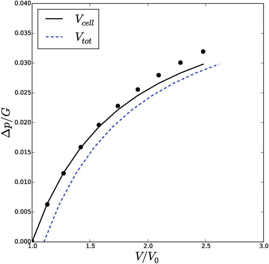
We have performed a series of computations for a range of deformations 1.0 < Λb < 1.4, and cell wall thickness B/R0 = 1.1. We compare these computations on the basis of inflation pressure, Δp/G, versus cell volume V/V0, the hydration at the outer radius of the cell wall ϕb as function of cell size r/R0. These relations can be compared to the analytical solutions for the p–V relation, eqn (12), and for the polymer volume fraction at the outer radius, eqn (13). Results are shown in Fig. 3 and 4. As one can observe the numerical solution quite follows the analytical solution, except for high inflation of the cell. As shown in Fig. 5, we have also computed the relative amount of water in the cell wall (RWC), which decreases from 25% to 15%. The decrease of the polymer volume fraction 〈ϕ〉 does show that the absolute amount of water is increasing, but not as fast as in the inflating cell (Fig. 4).
 | ||
| Fig. 3 Cell volume, Vcell and total volume of a spherical cell and its cell wall, Vtot, as function of turgor pressure Δp. The volumes are scaling with the cell volume in the stress free state, V0, and the pressure with the elastic modulus G of the cell in the reference state. | ||
 | ||
| Fig. 4 Average polymer volume fraction, 〈ϕ〉/ϕ0, as function of cell size r/R0, as follows from the numerical solution (symbols) and compared to the analytical solution for ϕbcf.eqn (13). | ||
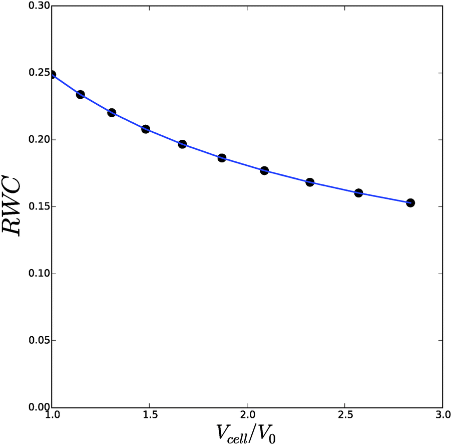 | ||
| Fig. 5 The relative cell wall water content (RWC) as function of the spherical cell volume Vcell/V0. Symbols follow from the numerical solution, and the line follows from the analytical solution. | ||
2.2 Cylindrical shells
For cylindrical geometries the principal directions for mechanical deformation are the radial direction, the circumferential direction, and the axial direction. The principal stretches are indicated with λr, λθ and λz for the radial, circumferential and axial direction respectively. For sake of simplicity we first like to investigate the two-dimensional problem with a constant axial stress, cf. ref. 42 The axial stretch is assumed equal to that of the zero stress state: . The solution method follows similar lines as the spherical case.
The incompressiblity condition for cylinders is:42
| λθλrλz = 1 | (14) |
 | (15) |
Using the condition of incompressibility, eqn (14), the stress difference becomes:
 | (16) |
 | (17) |
 | (18) |
 | (19) |
 | (20) |
 | (21) |
 | (22) |
 | (23) |
. We have also found this for the spherical case.
An approximate solution for the volume fraction , follows from the boundary condition at the outer surface, rr(r = b) = 0:
| ≈ b = (αΛb2Λz2)−1/(β+1) | (24) |
, Δp and Λa for any given inflation of the cylindrical shell Λb. We will compare these analytical expressions with the numerical solution, which is computed with the method described in the ESI.† We solve the problem for a range of stretches of the outer surface 1 < Λb < 1.6, and for a cell wall thickness of 5% of the cell radius. In Fig. 6 and 7 we have compared the numerical solutions with the analytical approximations for respectively (a) the distribution of the polymer fraction, (b) the turgor pressure – cell volume relation. The numerical results are comparable with the analytical results, except for high stretching of the cell wall. Deviations are due to the assumptions of homogeneous swelling in the analytical solutions. Comparing these figures with those for the spherical case, we observe little difference in the general trends – but there is a stronger deviation of the numerical solutions from the analytical solutions. The deviation of the average polymer fraction 〈ϕ〉 with that at the outer radius ϕb is of course a good indication of the inhomogeneity of deformation and hydration.
 | ||
| Fig. 6 Volume of the cell Vcell and the total volume, Vtot, as function of the turgor pressure in the cell Δp for an inflated cylindrical shell. The symbols indicate the analytical solution of the pressure–volume relation, eqn (23), assuming a homogeneous swelling and axial stretch of the gel. | ||
 | ||
| Fig. 7 Average polymer volume fraction at the outer radius of an inflated cylindrical shell, as function of cell size r/R0. Symbols indicate the numerical solution, and the solid line is the analytical solution for ϕb, cf.eqn (24). | ||
3 Advanced models
Real cell walls are composite materials showing more complex mechanical behaviour, such as strain hardening and anisotropic deformation, due to presence of aligned microfibers. In this section we investigate these kinds of mechanical behaviour. Strain hardening will be investigated for spherical cells, and anisotropic swelling for cylindrical cells.The modelling of this complex behaviour requires more elaborate strain energy functions, formulated in terms of the tensor invariants of the Cauchy tensor C = FTF, with F the deformation tensor, indicating the deformation of control volume elements. In absence of rotational deformation, the deformation tensor is a diagonal tensor containing the principal stretches λi, which are its eigenvalues. The eigenvalues of the Cauchy tensor are λi2. The tensor invariants of the Cauchy tensor are:
 | (25) |
3.1 Strain hardening
The first model incorporating strain hardening has been formulated by Fung,62,63 where | (26) |
0. Hence, at zero stress conditions it holds I1 = I1,0 = 3Λ02. A more proper expression of the strain energy function for strain hardening of swelling materials is: | (27) |
Recall that for swelling spherical shells holds λθ2λr = 1/, and hence
| I1 = (2λ2 + −2λ−4 − 3) | (28) |
 | (29) |
 | (30) |
The numerical results concerning the p–V relation are shown in Fig. 8, which are compared to experimental data for cells of bell pepper leaves. The experimental data has been fitted by estimating V0/Vmax = 3 and G = 100 kPa, using an assumed ratio of k/G = 5, and B/R0 = 1.06. Vmax is the maximal cell volume at full turgor. One can observe that the model now follows the experimental trend. At large strains (V/V0) further deformation of the cell requires an increasingly larger turgor pressure. This behaviour is quite opposite to inflating Neo-Hookean spherical shells, whose behaviour we have shown in Fig. 3. There, deformation at large strains requires increasingly smaller increments of turgor pressure. The latter behaviour is also well known for rubber balloons, but is absent in biological cells, thanks to the presence of microfibrils. For spherical cells the microfibrils are randomly oriented, leading to strain hardening, but isotropic deformation.
 | ||
| Fig. 8 Total volume of the cell Vtot as function of the turgor pressure in a spherical cell p, with strain hardening cell wall material. Experimental data (symbols) hold for pepper,60 and simulation data (line) hold for the modified Fung model eqn (27), with k/G = 5. The experimental data are rescaled with estimates of V0/Vmax = 3 and G = 100 kPa, which fitted the data. | ||
Viewing the debate in plant science on the amount of bound water, it is instructive to analyse the relative water content of the cell wall as function of the inflation. The change in RWC following the previous simulation are shown in Fig. 9. We observe large differences in RWC between hydrated and elastomeric shells at low values of inflation. RWC of the elastomeric shell varies only between 2% and 5%, while the RWC of the hydrated shell varies from 16% to 2%. The change of RWC of the strain hardening, hydrated shell with inflation is opposite to the change of a hydrated Neo-Hookean shell, where hydration increases with inflation. In real biological tissue the strain hardening prevents this phenomenon. The consequences of this behaviour will be discussed in the next section, after we have considered the effect of fibrils.
 | ||
| Fig. 9 Relative water content (RWC) in the cell wall as a function of cell volume Vcell/V0, computed for a hydrated and elastomeric shell. The elastomeric shell does not absorb water and thus retain a constant volume, which is taken equal to that of the hydrated shell at maximal inflation (Vcell/V0 = 3). | ||
3.2 Anisotropic deformation
We consider anisotropic deformation due to oriented fibrils in cylindrical cells. This cell model is representative for hyphen of fungi. Particular, we take the situation of the fruiting body of the Agaricus bisporus mushroom, which we have investigated earlier.8 In these hyphen chitin microfibrils are particularly oriented in the circumferential direction, while in mature cells we find also β-glucans, which predominantly oriented along the cylinder-axis.61 Effectively, we assume that the fibers have an orientation of ψ0 ≈ π/4.Strain energy functions for composite materials with oriented microfibrils have been developed in particular for arteries.65,78 The strain energy function has two contributions, W = Wiso + Waniso. The first part describes the isotropic deformation of the gel-like matrix, Wiso = Wiso(I1, I2, I3), while the second part describes the anisotropic deformation, which is a function of other invariants I4, I5, I6. These higher order invariants measure the stretch in the particular fibre direction t0 = (cos![[thin space (1/6-em)]](https://www.rsc.org/images/entities/char_2009.gif) ψ0, sinψ0), with ψ0 the fibre direction with respect to the cylinder rotational axis. The invariant is defined as:79
ψ0, sinψ0), with ψ0 the fibre direction with respect to the cylinder rotational axis. The invariant is defined as:79
| I4 = t0·Ct0 = λθ2cos2ψ0 + λz2sin2ψ0 | (31) |
 | (32) |
−2/30. Similar to the previous section we impose that at ϕ = ϕ0 the material is stress free.
The principle stresses are equal to:
 | (33) |
 | (34) |
 | ||
| Fig. 10 Volume of the cell Vcell and the total volume of cell and cell wall, Vtot, as function of the turgor pressure in the cell Δp for a swelling cylindrical shell reinforced with fibers. | ||
 | ||
| Fig. 11 Axial stretch Λz and radial stretch Λa at r = a of a swelling cylindrical shell reinforced with fibers, as function of the cell volume. The orientation angle of the fibers is θ ≈ π/4 leading to restricted expansion in radial direction, in comparison to the axial direction. | ||
 | ||
| Fig. 12 Relative water content (RWC) of the cell wall during inflation of cylindrical cell with fibers. | ||
It is interesting to note in simulations with small fiber angles ψ0 < π/8 (with data shown in ESI†), the behaviour is quite different, where the cell predominantly expands in the axial direction. This fiber configuration definitely promotes the growth of hyphen in axial direction, as has been observed experimentally.61
4 Impact of cellular structure on water holding capacity of plant food materials
The hydration behaviour of most plant food materials will be in line with Fig. 8. At harvest the cells are expected to be in full turgor. At full turgor the polymers the microfibrils in the cell wall are in tension, and render the strain hardening. A small, but not-negligible part of the water held in the tissue is held by the cell wall material. Because of the highly stretched state of the biopolymer network, with ϕ ≪ ϕ0, it is far less hydrated than in the stress free state. The behaviour of mushrooms, having cylindrical cells with oriented microfibrils, is more complicated. Though, the pressure–volume relation is similar to that of plant foods with more spherical cells. Its different behaviour is more apparent in the stretching in the axial direction, which extends during strain hardening – a reflection of the propensity of the hyphens to grow in axial direction. Due to the axial extension the change in RWC is much less pronounced as for spherical cells.Many foods will be processed prior to consumption, via cutting, heating or freezing. This processing makes that the cell membrane looses its integrity. Consequently, solutes from the vacuole will diffuse out of the cell, and the osmotic and turgor pressure are lost. The cell wall will return to the zero-stress state. In this state the cell volume V0 is much less than in the full turgor state. However, in the stress-free state the cell wall is more hydrated than in the full turgor state, see Fig. 8 and 12. Furthermore, the solutes from the vacuole will diffuse into the cell wall. Hence, they will improve the hydration of the cell wall material via increase of the water activity.7,8 Consequently, a significant part of the water liberated by the loss of cell volume, will be resorbed by the unstressed cell wall material and solutes diffused into the cell wall material. After loosing the cell membrane integrity, the water held inside the cell will be held in pores in between the plasmolyzed cell and cell wall. This water is held by capillary forces, and is easily lost via gravity or via the mechanical load during oral processing.
Often, the net effect of processing is that the water holding will be less than for the fresh food, having intact cell membranes. In practice, this loss of water holding is noticed via the water loss (drip) after thawing of frozen plant foods.17 The effect of cooking is more complicated because proteins denature and crosslinks in the cell wall material will be hydrolysed. Proteins denaturation will lower water holding,11 while hydrolysis of crosslinks will increase it. At temperatures above 80 degrees there is thermal hydrolysis of pectin, which will lower the number of crosslinks in the polymer network – which will increase the water holding. However, if the heating is performed slowly, enzymes like PME (Pectin-Methyl-Esterase) will be activated around 50 degrees, which will increase the crosslinks if calcium is present.80
It appears that freezing is more appropriate to study the effect of the cellular structure on the water holding capacity.81 However, during freezing the cell walls of several cells will be collapsed on top of each other (due to the growing ice crystals).82 During compression new crosslinks will be formed. This becomes apparent due to the inability of the cells to reswell completely during rehydration after freeze-drying.83 A more appropriate method will be electroporation of the cell membranes as with the Pulsed Electric Field method, provided that the temperature rise due to Joule heating is limited.84
Also for plant science it is important to note the ability of the cell wall material to retain more water in situations, where the cell wall is less stressed than at full turgor. This situation occurs during drought stress. During loss of turgor the amount of symplasmatic water decreases, but a significant part of it can be resorbed by the apoplast because of its enhanced hydration. Our findings show that the hypothesis in plant science that bound water is independent of cell volume should be reconsidered.
Summarizing, this study implies that in models for water relations in plants one needs account for the water held in the apoplast. The models similar to those presented in this paper can be used for this purpose.
5 Conclusions
In this paper we have presented hyper-elastic models for the investigation of the hydration of cellular tissue. We have used pressurized, spherical and cylindrical shells as model systems for walled cells, as can be found in plants and fungi. The pressurized internal cavity represent the cell bounded by the cell wall, that is impermeable to solutes inside the vacuole. The internal pressure represents the turgor pressure. The shell represents the polymeric material of the cell: the cytoplasm and cell wall. The shell has been modelled as a hydrogel and a composite material with microfibrils. We have solved these models numerically, and obtained how the cell volume changes as function of the internal pressure.Furthermore, the hydration of the cell wall changes with cell volume. The composite character of the cell wall leads to strain hardening, and anisotropic deformation in case of cylindrical cells. Strain hardening of the cell wall becomes apparent if the cell is in the full turgor state. For cells in this state, it requires a much larger increase of pressure to obtain cell volume change, than compared with cells in the zero stress state. Anisotropic deformation is induced to microfibrils with a preferred orientation.
We have interpreted the results for the impact of the cellular structure on the water holding capacity of plant food materials. From the comparison of the cell volume and the hydration of the cell wall of cells in the zero stress state and the full turgor state, we conclude that the cellular structure, and particularly the integrity of the cell membrane has a significant impact on the water holding capacity. This aspect has hardly been acknowledged in food science, dealing with water holding capacity. The theory we are developing for water holding capacity of foods, definitely has to be extended to account for the cellular structure. The presented hyperelastic models provide the proper framework for that.
The found results have significant impact for other scientific fields. One such field is in plant science, dealing with water relations. There, the hydration of cell wall material is hardly acknowledged – but our results show that the cell wall (or rather apoplast) gives a significant contribution to the hydration of the tissue.15 Its significance is even larger under drought stress. Moreover, mucilage-like apoplast in cactus stems and plant roots have clearly a function to attract and store water, almost the similar amount as stored in the cells.85,86 Furthermore, water transport in plants is mainly via the apoplast (the connected cell walls of all cells in the tissue), and is enhanced if the cells are dehydrated. Another field is the post harvest biology, where one has found that cell wall hydration and swelling are higly relevant processes for of fruit ripening.26,87 Next to ripening, the softening of fruit is also controlled by moisture loss via evaporation. Recently, the water transport problem in fruit are approached with hyperelastic models, but which neglect the water holding capacity and swelling/shrinkage of the cell wall material.88–90 These models can be extended like the models presented in this paper. The multiscale simulation approach for the water transport in fruit, extended with more appropriate microscale models as presented here, is also the proper framework for modelling drying and shrinkage of any food material, based on cellular tissue.
The model system used, of an pressurized elastic, hydrated shell is also usefull for bubble expansion during bread baking, and snacks frying.91–93 The internal pressure is generated by the gas inside the bubble. The expansion will be restrained by the visco-elasticity of the matrix, which can be regarded as a hydrated biopolymer network. One often associates strain hardening to the gluten matrix in bread dough, which is important for the stability of bubbles during proofing.94 The presented models are well suited for these problems, if extended for the viscous properties of the matrix.
For the field of responsive gels the presented model can also mean a step forward. The current models in this field are largely based on the Flory–Huggins theory for the osmotic pressure, Πmix, and the Neo-Hookean strain energy function.95–97 But in more advanced models, incorporating strain hardening or anisotropic deformation due to fibrils, swelling has not been taken into account. This paper shows examples how to extend that. Furthermore, the use of the expression of the osmotic pressure from the Cloizeaux scaling law could benefit the field, because (1) it allows for more analytical solutions given simple geometries – instead of analytical taylor series expansions,98 and (2) it has less model parameters. One should note that the Cloizeaux scaling is only applicable in the semi-dilute regime. However, for (biopolymeric) hydrogels in the concentrated regime also the Flory–Huggins theory must be modified via making the interaction parameter dependent on the polymer volume fraction – to account for effects of hydrogen bonding.58,99
References
- M. T. Tyree and P. G. Jarvis, Water in tissues and cells, Physiological plant ecology II, Springer, 1982, pp. 35–77 Search PubMed.
- A. S. Szczesniak and R. Ilker, The meaning of textural charcteristics-juiciness in plant foodstuffs, J. Texture Stud., 1988, 19(1), 61–78 CrossRef PubMed.
- E. Huff-Lonergan and S. M. Lonergan, Mechanisms of water-holding capacity of meat: the role of postmortem biochemical and structural changes, Meat Sci., 2005, 71(1), 194–204 CrossRef CAS PubMed.
- P. Gervais and P. Molin, The role of water in solid-state fermentation, Biochem. Eng. J., 2003, 13(2), 85–101 CrossRef CAS.
- R. G. M. van der Sman, Modeling cooking of chicken meat in industrial tunnel ovens with the flory–rehner theory, Meat Sci., 2013, 95(4), 940–957 CrossRef CAS PubMed.
- R. G. M. van der Sman, E. Paudel, A. Voda and S. Khalloufi, Hydration properties of vegetable foods explained by flory–rehner theory, Food Res. Int., 2013, 54(1), 804–811 CrossRef CAS PubMed.
- R. G. M. van der Sman, F. J. Vergeldt, H. Van As, G. Van Dalen, A. Voda and J. P. M. Van Duynhoven, Multiphysics pore-scale model for the rehydration of porous foods, Innovative Food Sci. Emerging Technol., 2014, 24, 69–79 CrossRef PubMed.
- E. Paudel, R. M. Boom and R. G. M. van der Sman, Change in water-holding capacity in mushroom with temperature analyzed by flory-rehner theory, Food Bioprocess Technol., 2014, 1–11 Search PubMed.
- P. J. Flory and J. Rehner Jr, Statistical mechanics of cross-linked polymer networks ii. swelling, J. Chem. Phys., 1943, 11(11), 521–526 CrossRef CAS PubMed.
- R. G. M. Van der Sman, Moisture transport during cooking of meat: an analysis based on flory–rehner theory, Meat Sci., 2007, 76(4), 730–738 CrossRef CAS PubMed.
- R. G. M. van der Sman, Thermodynamics of meat proteins, Food Hydrocolloids, 2012, 27(2), 529–535 CrossRef CAS PubMed.
- H. H. Wiebe, Matric potential of several plant tissues and biocolloids, Plant Physiol., 1966, 41(9), 1439–1442 CrossRef CAS PubMed.
- J. H. McClendon, The balance of forces generated by the water potential in the cell-wall-matrix–a model, Am. J. Bot., 1981, 1263–1268 CrossRef.
- S. P. Hardegree, Derivation of plant cell wall water content by examination of the water-holding capacity of membrane-disrupted tissues, J. Exp. Bot., 1989, 40(10), 1099–1104 CrossRef PubMed.
- I. F. Wardlaw, Viewpoint: consideration of apoplastic water in plant organs: a reminder, Funct. Plant Biol., 2005, 32(6), 561–569 CrossRef.
- A. R. Rahman, W. L. Henning and D. E. Westcott, Histological and physical changes in carrots as affected by blanching, cooking, freezing, freeze drying and compression, J. Food Sci., 1971, 36(3), 500–502 CrossRef PubMed.
- S. Phothiset and S. Charoenrein, Effects of freezing and thawing on texture, microstructure and cell wall composition changes in papaya tissues, J. Sci. Food Agric., 2014, 94(2), 189–196 CrossRef CAS PubMed.
- A. Rascio, G. Nicastro, E. Carlino and N. Di Fonzo, Differences for bound water content as estimated by pressure–volume and adsorption isotherm curves, Plant Sci., 2005, 169(2), 395–401 CrossRef CAS PubMed.
- M. Santakumari and G. A. Berkowitz, Protoplast volume: water potential relationship and bound water fraction in spinach leaves, Plant Physiol., 1989, 91(1), 13–18 CrossRef CAS PubMed.
- M. Barg, M. V. Agüero, A. Yommi and S. I. Roura, Evolution of plant water status indices during butterhead lettuce growth and its impact on post-storage quality, J. Sci. Food Agric., 2009, 89(3), 422–429 CrossRef CAS PubMed.
- S. Maatallah, M. E. Ghanem, A. Albouchi, E. Bizid and S. Lutts, A greenhouse investigation of responses to different water stress regimes of laurus nobilis trees from two climatic regions, J. Arid Environ., 2010, 74(3), 327–337 CrossRef PubMed.
- F. R. Harker, M. G. H. Stec, I. C. Hallett and C. L. Bennett, Texture of parenchymatous plant tissue: a comparison between tensile and other instrumental and sensory measurements of tissue strength and juiciness, Postharvest Biol. Technol., 1997, 11(2), 63–72 CrossRef.
- M. U. H. Joardder, R. J. Brown, C. Kumar and M. A. Karim, Effect of cell wall properties on porosity and shrinkage of dried apple, Int. J. Food Prop., 2015, 18(10), 2327–2337 CrossRef PubMed.
- D. M. Bruce, Mathematical modelling of the cellular mechanics of plants, Philos. Trans. R. Soc. London, Ser. B, 2003, 358(1437), 1437–1444 CrossRef PubMed.
- R. Ilker and A. S. Szczesniak, Structural and chemical bases for texture of plant foodstuffs, J. Texture Stud., 1990, 21(1), 1–36 CrossRef CAS PubMed.
- R. J. Redgwell, E. MacRae, I. Hallett, M. Fischer, J. Perry and R. Harker, In vivo and in vitro swelling of cell walls during fruit ripening, Planta, 1997, 203(2), 162–173 CrossRef CAS.
- L. R. G. Treloar, The elasticity and related properties of rubbers, Rep. Prog. Phys., 1973, 36(7), 755 CrossRef CAS.
- L. R. G. Treloar, The physics of rubber elasticity, Oxford University Press, 1975 Search PubMed.
- L. R. G. Treloar, Swelling of bonded-rubber cylinders, Polymer, 1976, 17(2), 142–146 CrossRef CAS.
- D. R. P. Hettiaratchi and J. R. O'callaghan, A membrane model of plant cell extension, J. Theor. Biol., 1974, 45(2), 459–465 CrossRef CAS.
- H. I. Wu and P. J. H. Sharpe, Stomatal mechanics ii*: material properties of guard cell walls, Plant, Cell Environ., 1979, 2(3), 235–244 CrossRef PubMed.
- H. Wu, R. D. Spence, P. J. H. Sharpe and J. D. Goeschl, Cell wall elasticity: I. a critique of the bulk elastic modulus approach and an analysis using polymer elastic principles, Plant, Cell Environ., 1985, 8(8), 563–570 CrossRef CAS PubMed.
- D. R. P. Hettiaratchi and J. R. O'Callaghan, Structural mechanics of plant cells, J. Theor. Biol., 1978, 74(2), 235–257 CrossRef CAS.
- M. A. J. Chaplain, The strain energy function of an ideal plant cell wall, J. Theor. Biol., 1993, 163(1), 77–97 CrossRef.
- W. Hong, Z. Liu and Z. Suo, Inhomogeneous swelling of a gel in equilibrium with a solvent and mechanical load, Int. J. Solids Struct., 2009, 46(17), 3282–3289 CrossRef CAS PubMed.
- W. Hong, X. Zhao and Z. Suo, Large deformation and electrochemistry of polyelectrolyte gels, J. Mech. Phys. Solids, 2010, 58(4), 558–577 CrossRef CAS PubMed.
- S. Cai and Z. Suo, Mechanics and chemical thermodynamics of phase transition in temperature-sensitive hydrogels, J. Mech. Phys. Solids, 2011, 59(11), 2259–2278 CrossRef CAS PubMed.
- J. Klier and N. A. Peppas, Anomalous penetrant transport in glassy polymers: 4. stresses in partially swollen polymers, Polymer, 1987, 28(11), 1851–1859 CrossRef CAS.
- R. S. Harland, J. Klier and N. A. Peppas, Thermodynamic models for swelling of heterogeneous networks, J. Appl. Polym. Sci., 1990, 41(1–2), 249–265 CrossRef CAS PubMed.
- N. A. Peppas and J. Klier, Controlled release by using poly (methacrylic acid-g-ethylene glycol) hydrogels, J. Controlled Release, 1991, 16(1), 203–214 CrossRef CAS.
- B. Amsden, A model for osmotic pressure driven release from cylindrical rubbery polymer matrices, J. Controlled Release, 2003, 93(3), 249–258 CrossRef CAS PubMed.
- T. J. Pence and H. Tsai, Swelling-induced microchannel formation in nonlinear elasticity, IMA journal of applied mathematics, 2005, 70(1), 173–189 CrossRef.
- T. J. Pence and H. Tsai, Swelling-induced cavitation of elastic spheres, Math. Mech. Solids, 2006, 11(5), 527–551 CrossRef PubMed.
- F. P. Duda, A. C. Souza and E. Fried, Solvent uptake and cavitation, J. Mech. Phys. Solids, 2011, 59(11), 2341–2354 CrossRef CAS PubMed.
- R. Marcombe, S. Cai, W. Hong, X. Zhao, Y. Lapusta and Z. Suo, A theory of constrained swelling of a ph-sensitive hydrogel, Soft Matter, 2010, 6(4), 784–793 RSC.
- A. Goriely and M. Tabor, Biomechanical models of hyphal growth in actinomycetes, J. Theor. Biol., 2003, 222(2), 211–218 CrossRef.
- M. B. Amar and A. Goriely, Growth and instability in elastic tissues, J. Mech. Phys. Solids, 2005, 53(10), 2284–2319 CrossRef PubMed.
- A. Goriely, D. E. Moulton and R. Vandiver, Elastic cavitation, tube hollowing, and differential growth in plants and biological tissues, EPL, 2010, 91(1), 18001 CrossRef.
- Y.-P. Cao, B. Li and X.-Q. Feng, Surface wrinkling and folding of core–shell soft cylinders, Soft Matter, 2012, 8(2), 556–562 RSC.
- B. Li, G.-K. Xu and X.-Q. Feng, Tissue–growth model for the swelling analysis of core–shell hydrogels, Soft Mater., 2013, 11(2), 117–124 CrossRef PubMed.
- Z. Liu, S. Swaddiwudhipong and W. Hong, Pattern formation in plants via instability theory of hydrogels, Soft Matter, 2013, 9(2), 577–587 RSC.
- M. Warner, B. L. Thiel and A. M. Donald, The elasticity and failure of fluid-filled cellular solids: theory and experiment, Proc. Natl. Acad. Sci. U. S. A., 2000, 97(4), 1370–1375 CrossRef CAS PubMed.
- M. Amon and C. D. Denson, A study of the dynamics of foam growth: analysis of the growth of closely spaced spherical bubbles, Polym. Eng. Sci., 1984, 24(13), 1026–1034 CAS.
- H. X. Zhu and J. R. Melrose, A mechanics model for the compression of plant and vegetative tissues, J. Theor. Biol., 2003, 221(1), 89–101 CrossRef CAS.
- S. L. Everitt, O. G. Harlen and H. J. Wilson, Bubble growth in a two-dimensional viscoelastic foam, J. Non-Newtonian Fluid Mech., 2006, 137(1), 46–59 CrossRef CAS PubMed.
- J. D. Cloizeaux, The lagrangian theory of polymer solutions at intermediate concentrations, J. Phys., 1975, 36(4), 281–291 Search PubMed.
- P.-G. De Gennes, Scaling concepts in polymer physics, Cornell university press, 1979 Search PubMed.
- R. G. M. van der Sman, Biopolymer gel swelling analysed with scaling laws and flory–rehner theory, Food Hydrocolloids, 2015, 48, 94–101 CrossRef CAS PubMed.
- G. O. Michalenko, H. R. Hohl and D. Rast, Chemistry and architecture of the mycelial wall of agaricus bisporus, J. Gen. Microbiol., 1976, 92(2), 251–262 CrossRef CAS.
- H.-i. Wu, R. D. Spence and P. J. H. Sharpe, Plant cell wall elasticity ii: polymer elastic properties of the microfibrils, J. Theor. Biol., 1988, 133(2), 239–253 CrossRef.
- P. C. Mol, C. A. Vermeulen and J. G. H. Wessels, Diffuse extension of hyphae in stipes of agaricus bisporus may be based on a unique wall structure, Mycol. Res., 1990, 94(4), 480–488 CrossRef.
- Y. C. Fung, K. Fronek and P. Patitucci, Pseudoelasticity of arteries and the choice of its mathematical expression, Am. J. Physiol.: Heart Circ. Physiol., 1979, 237(5), H620–H631 CAS.
- Y.-C. Fung, Biomechanics, Springer, 1990 Search PubMed.
- K. A. Erk, K. J. Henderson and K. R. Shull, Strain stiffening in synthetic and biopolymer networks, Biomacromolecules, 2010, 11(5), 1358–1363 CrossRef CAS PubMed.
- G. A. Holzapfel, T. C. Gasser and R. W. Ogden, A new constitutive framework for arterial wall mechanics and a comparative study of material models, Journal of elasticity and the physical science of solids, 2000, 61(1–3), 1–48 CrossRef.
- H. Demirkoparan and T. J. Pence, Swelling of an internally pressurized nonlinearly elastic tube with fiber reinforcing, Int. J. Solids Struct., 2007, 44(11), 4009–4029 CrossRef PubMed.
- H. Demirkoparan and T. J. Pence, Torsional swelling of a hyperelastic tube with helically wound reinforcement, J. Elast., 2008, 92(1), 61–90 CrossRef.
- T. M. Beecher, N. Magan and K. S. Burton, Water potentials and soluble carbohydrate concentrations in tissues of freshly harvested and stored mushrooms (agaricus bisporus), Postharvest Biol. Technol., 2001, 22(2), 121–131 CrossRef CAS.
- H.-H. Dai and Z. Song, Some analytical formulas for the equilibrium states of a swollen hydrogel shell, Soft Matter, 2011, 7(18), 8473–8483 RSC.
- H. Hinsken and W. Borchard, Continuous swelling pressure equilibria of the systemκ-carrageenan/water, Colloid Polym. Sci., 1995, 273(10), 913–925 CAS.
- A. R. Khokhlov, Swelling and collapse of polymer networks, Polymer, 1980, 21(4), 376–380 CrossRef CAS.
- M. Quesada-Pérez, J. A. Maroto-Centeno, J. Forcada and R. Hidalgo-Alvarez, Gel swelling theories: the classical formalism and recent approaches, Soft Matter, 2011, 7(22), 10536–10547 RSC.
- J. Li, Y. Hu, J. J. Vlassak and Z. Suo, Experimental determination of equations of state for ideal elastomeric gels, Soft Matter, 2012, 8(31), 8121–8128 RSC.
- J. Li, Z. Suo and J. J. Vlassak, A model of ideal elastomeric gels for polyelectrolyte gels, Soft Matter, 2014, 10(15), 2582–2590 RSC.
- T. Hino and J. M. Prausnitz, Swelling equilibria for heterogeneous polyacrylamide gels, J. Appl. Polym. Sci., 1996, 62(10), 1635–1640 CrossRef CAS.
- M. Shibayama, Y. Shirotani, H. Hirose and S. Nomura, Simple scaling rules on swollen and shrunken polymer gels, Macromolecules, 1997, 30(23), 7307–7312 CrossRef CAS.
- M. A. Zulliger, P. Fridez, K. Hayashi and N. Stergiopulos, A strain energy function for arteries accounting for wall composition and structure, J. Biomech., 2004, 37(7), 989–1000 CrossRef PubMed.
- Y. Zhu, X. Y. Luo and R. W. Ogden, Nonlinear axisymmetric deformations of an elastic tube under external pressure, Eur. J. Mech. A Solids, 2010, 29(2), 216–229 CrossRef PubMed.
- W. G. Li, J. Going, N. A. Hill and X. Y. Luo, Breaking analysis of artificial elastic tubes and human artery, Int. J. Appl. Mech. Eng., 2013, 5, 1350024 CrossRef.
- H. Kunzek, R. Kabbert and D. Gloyna, Aspects of material science in food processing: changes in plant cell walls of fruits and vegetables, Z. Lebensm.-Unters. -Forsch. A, 1999, 208(4), 233–250 CrossRef CAS.
- F. Gómez and I. Sjöholm, Applying biochemical and physiological principles in the industrial freezing of vegetables: a case study on carrots, Trends Food Sci. Technol., 2004, 15(1), 39–43 CrossRef PubMed.
- A. Voda, N. Homan, M. Witek, A. Duijster, G. van Dalen, R. van der Sman, J. Nijsse, L. van Vliet, H. Van As and J. van Duynhoven, The impact of freeze-drying on microstructure and rehydration properties of carrot, Food Res. Int., 2012, 49(2), 687–693 CrossRef CAS PubMed.
- F. J. Vergeldt, G. van Dalen, A. J. Duijster, A. Voda, S. Khalloufi, L. J. van Vliet, H. Van As, J. P. M. van Duynhoven and R. G. M. van der Sman, Rehydration kinetics of freeze-dried carrots, Innovative Food Sci. Emerging Technol., 2014, 24, 40–47 CrossRef PubMed.
- M. Bazhal, N. Lebovka and E. Vorobiev, Optimisation of pulsed electric field strength for electroplasmolysis of vegetable tissues, Biosyst. Eng., 2003, 86(3), 339–345 CrossRef.
- P. S. Nobel, J. Cavelier and J. L. Andrade, Mucilage in cacti: its apoplastic capacitance, associated solutes, and influence on tissue 5, J. Exp. Bot., 1992, 43(5), 641–648 CrossRef PubMed.
- M. E. McCully and J. S. Boyer, The expansion of maize root-cap mucilage during hydration. 3. changes in water potential and water content, Physiol. Plant., 1997, 99(1), 169–177 CrossRef CAS PubMed.
- C. Frenkel and T. G. Hartman, Decrease in fruit moisture content heralds and might launch the onset of ripening processes, J. Food Sci., 2012, 77(10), S365–S376 CrossRef CAS PubMed.
- W. A. Aregawi, T. Defraeye, P. Verboven, E. Herremans, G. De Roeck and B. M. Nicolai, Modeling of coupled water transport and large deformation during dehydration of apple tissue, Food Bioprocess Technol., 2013, 6(8), 1963–1978 CrossRef.
- S. W. Fanta, M. K. Abera, W. A. Aregawi, Q. T. Ho, P. Verboven, J. Carmeliet and B. M. Nicolai, Microscale modeling of coupled water transport and mechanical deformation of fruit tissue during dehydration, J. Food Eng., 2014, 124, 86–96 CrossRef CAS PubMed.
- W. A. Aregawi, M. K. Abera, S. W. Fanta, P. Verboven and B. Nicolai, Prediction of water loss and viscoelastic deformation of apple tissue using a multiscale model, J. Phys.: Condens. Matter, 2014, 26(46), 464111 CrossRef PubMed.
- P. Babin, G. D. Valle, H. Chiron, P. Cloetens, J. Hoszowska, P. Pernot, A. L. Réguerre, L. Salvo and R. Dendievel, Fast x-ray tomography analysis of bubble growth and foam setting during breadmaking, J. Cereal Sci., 2006, 43(3), 393–397 CrossRef PubMed.
- R. G. M. van der Sman and J. Broeze, Effects of salt on the expansion of starchy snacks: a multiscale analysis, Food Funct., 2014, 5(12), 3076–3082 CAS.
- R. G. M. van der Sman and J. Broeze, Multiscale analysis of structure development in expanded starch snacks, J. Phys.: Condens. Matter, 2014, 26(46), 464103 CrossRef CAS PubMed.
- B. J. Dobraszczyk and C. A. Roberts, Strain hardening and dough gas cell-wall failure in biaxial extension, J. Cereal Sci., 1994, 20(3), 265–274 CrossRef.
- S. Cai, D. Chen, Z. Suo and R. C. Hayward, Creasing instability of elastomer films, Soft Matter, 2012, 8(5), 1301–1304 RSC.
- D. Okumura, T. Kuwayama and N. Ohno, Effect of geometrical imperfections on swelling-induced buckling patterns in gel films with a square lattice of holes, Int. J. Solids Struct., 2014, 51(1), 154–163 CrossRef CAS PubMed.
- A. D. Drozdov, Equilibrium swelling of core–shell composite microgels, Meccanica, 2015, 1–14 CAS.
- X. Chen and H.-H. Dai, Asymptotic solutions and new insights for cylinder and core–shell polymer gels in a solvent, Soft Matter, 2013, 9(36), 8664–8677 RSC.
- R. G. M. van der Sman and M. B. J. Meinders, Prediction of the state diagram of starch water mixtures using the flory–huggins free volume theory, Soft Matter, 2011, 7(2), 429–442 RSC.
Footnote |
| † Electronic supplementary information (ESI) available. See DOI: 10.1039/c5sm01032b |
| This journal is © The Royal Society of Chemistry 2015 |