
 Open Access Article
 This Open Access Article is licensed under a Creative Commons Attribution-Non Commercial 3.0 Unported Licence
A model for aging under deformation field, residual stresses and strains in soft glassy materials†
Yogesh M.
Joshi
*
Department of Chemical Engineering, Indian Institute of Technology Kanpur, Kanpur 208016, India. E-mail: joshi@iitk.ac.in
First published on 23rd February 2015
Abstract
A model is proposed that considers aging and rejuvenation in a soft glassy material as, respectively, a decrease and an increase in free energy. The aging term is weighted by an inverse of characteristic relaxation time suggesting that greater mobility of the constituents induces faster aging in a material. A dependence of relaxation time on free energy is proposed, which under quiescent conditions leads to a power law dependence of relaxation time on waiting time as observed experimentally. The model considers two cases, namely, a constant modulus when aging is entropy controlled and a time dependent modulus. In the former and the latter cases the model has, respectively, two and three experimentally measurable parameters that are physically meaningful. Overall, the model predicts how the material undergoes aging and approaches a rejuvenated state under the application of a deformation field. In particular, the model proposes distinctions between various kinds of rheological effects for different combinations of parameters. Interestingly, when the relaxation time evolution is stronger than linear, the model predicts various features observed in soft glassy materials such as thixotropic and constant yield stress, thixotropic shear banding, and the presence of residual stress and strain.
I. Introduction
Glassy soft materials such as concentrated suspensions and emulsions, foams, colloidal gels and a variety of different pastes are routinely used in industry as well as in everyday life. In this class of materials either the crowding of constituting entities and/or inter-particle attractive/repulsive interactions kinetically restrict the same from achieving equilibrium structures.1–3 However, microscopic mobility of the constituents arising from the thermal energy induces slow but steady structural evolution to form progressively more stable structures. This process of structural recovery is also known as physical aging,3 wherein the free energy of a material decreases as a function of time. If such a material is subjected to a deformation field, the structure evolved during aging gets altered, which usually causes the reversal of physical aging.4 The corresponding process is termed as rejuvenation. The rheological behavior of soft glassy materials (SGMs) is determined by competition between aging and rejuvenation for a given deformation field, which leads to many unusual and sometimes opposite effects such as time dependent yield stress,5–8 viscosity bifurcation,9,10 shear banding,5,11–14 delayed yielding,15,16 delayed solidification,17,18 overaging,19–21 presence of residual stresses22 and strains,23,24etc. In this paper we present a model that accounts for aging and rejuvenation in terms of evolution of free energy influenced by the deformation field. In addition to describing many of the above mentioned experimental behavior, the model prescribes a criterion for their occurrence based on the behavior under quiescent conditions.In the process of physical aging the relaxation time and sometimes elastic modulus of a glassy material evolve as a function of time while attaining progressively lower free energy states.24–29 As a result the solid-like character of a glassy material increases gradually as a function of time. Application of a deformation field attenuates the rate of evolution of relaxation time and eventually causes a decrease in relaxation time. In the limit of a sufficiently strong deformation field, the time evolution of the material stops and the material (shear) melts to form a liquid.15,24,27 Subsequent to the shear melting the physical aging reinitiates in a material. In the rheology literature this phenomenon is represented as thixotropy.30 SGMs also demonstrate yield stress; and depending on whether the yield stress evolves with time or remains constant, the materials are termed as thixotropic and simple yield stress materials, respectively.5 While the recent literature indeed proposes the existence of real yield stress in both thixotropic and simple yield stress materials, it has long been argued in the rheology literature that the existence of real yield stress is a myth and in reality a material only undergoes transition from a weak flowing regime to a strong flowing regime leading to so called engineering yield stress.7
SGMs have also been observed to demonstrate shear banding.31 In thixotropic yield stress materials, constitutionally the stress does not exist for strain rates below the critical value.5,13 Consequently, the imposition of a strain rate below the critical value leads to banding, wherein one band flows with the critical strain rate while the other does not flow. The relative width of each band depends on the values of imposed and critical strain rates. The existence of thixotropic yield stress also leads to viscosity bifurcation wherein the application of stress below the threshold value cannot stop the divergence of viscosity.9 On the other hand, the application of stress above the threshold causes the viscosity to achieve a finite value as a function of time. Rather than showing viscosity bifurcation, some materials show delayed solidification or delayed yielding. In the former, the application of stress, no matter how large it is, leads to either constant viscosity or a decrease in viscosity for a prolonged period before showing sudden enhancement.17 In delayed yielding, on the other hand, the application of stress cannot restrict enhancement in viscosity as a function of time in the initial period. However, in the limit of long times, the material undergoes sudden yielding thereby inducing fluidity.15,16
Under the application of a strong deformation field a material rejuvenates, and consequently the material is in a liquid state. The aging of a material subsequent to rejuvenation can be monitored by applying no stress or constant strain. In the former case of no stress, strain recovers as a function of time. Interestingly, however, if a material is subjected to creep during the period of strain recovery, the resultant strain may show a non-monotonic dependence on time, causing an apparent paradox as observed experimentally.23,24,32 Instead, if the strain is kept constant subsequent to the rejuvenation, the stress relaxes. However, depending on the characteristic feature of an SGM, the stress may show complete relaxation, power law dependence on time or a non-zero plateau (residual stress) in the limit of long times.22 However, the effect of aging on both of the phenomena, stress relaxation as well as strain recovery, has not been studied theoretically.
Various models that capture the rheological behavior of thixotropic materials have been proposed in the rheology literature.33 According to Mewis and Wagner,30 there are three aspects common in such modeling approaches. The first one is the evolution equation of the empirical structure parameter (usually represented by λ), which indicates the instantaneous state of a material. The second aspect is a relationship between λ and the rheological properties; while the third aspect is a constitutive equation that relates stress, strain and their derivatives through the rheological properties. The evolution equation of λ essentially contains two terms: a buildup term and a destruction term representing aging and rejuvenation, respectively. A comprehensive list of various expressions representing the build up and destruction terms along with the constitutive equations have been reported in the literature.30,33 Coussot proposed that the models in this class can be represented by a simple evolution expression for an arbitrary structure parameter λ, given by:34
 | (1) |
This expression suggests that the structure builds up with a constant timescale T0, while the destruction term is proportional to the strain rate ![[small gamma, Greek, dot above]](https://www.rsc.org/images/entities/i_char_e0a2.gif) with a prefactor Q that grows with λ. Coussot and coworkers9 showed that steady state stress and strain rate show a non-monotonic relation for a suitable choice of Q(λ) and viscosity (η(λ)). A class of models has also been proposed by representing λ as a fluidity that is an inverse of characteristic relaxation time.35,36 By considering various functional forms for the decrease in fluidity as a function of time (aging) and increase in the same as a function of deformation field (rejuvenation), Derec et al.35 and Picard et al.36 proposed different kinds of relationships between steady state stress and strain rate, including non-monotonic, which lead to variety of rheological phenomena shown by SGMs. Particularly the non-monotonic relation between steady state stress and strain rate leads to the qualitative prediction of various important types of rheological behavior reported for SGMs such as viscosity bifurcation, thixotropic yield stress and shear banding.
with a prefactor Q that grows with λ. Coussot and coworkers9 showed that steady state stress and strain rate show a non-monotonic relation for a suitable choice of Q(λ) and viscosity (η(λ)). A class of models has also been proposed by representing λ as a fluidity that is an inverse of characteristic relaxation time.35,36 By considering various functional forms for the decrease in fluidity as a function of time (aging) and increase in the same as a function of deformation field (rejuvenation), Derec et al.35 and Picard et al.36 proposed different kinds of relationships between steady state stress and strain rate, including non-monotonic, which lead to variety of rheological phenomena shown by SGMs. Particularly the non-monotonic relation between steady state stress and strain rate leads to the qualitative prediction of various important types of rheological behavior reported for SGMs such as viscosity bifurcation, thixotropic yield stress and shear banding.
While thixotropy/fluidity models tend to capture the essence of the physics associated with soft glassy dynamics, more rigorous models such as the soft glassy rheology (SGR) model and mode coupling theory (MCT) have been developed to study soft glassy dynamics. MCT is developed, in principle, for colloidal glasses wherein cage diffusion is known to become progressively sluggish as the particle concentration increases.37 MCT considers that since the cages are nothing but the surrounding particles, whose diffusion is also similarly affected, there exists a forward feedback mechanism that impedes relaxation of the fluctuations in density. Consequently, at a certain concentration the relaxation time diverges causing glass transition. MCT predicts the onset of glass transition well, and has been modified to include the effect of deformation field.6 The present versions of MCT, however, do not demonstrate any physical aging. The SGR model,38 on the other hand, is primarily based on aging dynamics considered in Bouchaud's trap model.39 The SGR model divides a material into mesoscopic domains and tracks the evolution of each as a function of time for a given deformation field. The effect of deformation field in the SGR model is considered through strain and is modeled as an activated process. The relaxation time of an individual mesoscopic element directly depends on strain as:  where E is the depth of the energy well in which an element is trapped, τ0 is the inverse of attempt frequency and
  is the energy gained by the element due to strain γ. The noise temperature x suggests the energy available for activation, and in a normalized form x = 1 is a point of glass transition below which the material shows physical aging. Upon cage diffusion elements get trapped in a new cage whose depth is obtained from a prior distribution. For a given deformation field and at any point in time, the distribution of energy well depths, in which elements are trapped, is related to stress which gives the constitutive equation. Both MCT and the SGR model demonstrate many experimentally observed rheological behaviors of SGMs;1 and although they are mathematically and computationally demanding, these models render microscopic insight into the glassy dynamics intercepted by the deformation field.
Physical aging takes place not just in SGMs but also in polymer glasses, wherein enthalpy decreases as a function of time.40,41 Aging in polymer glasses is usually modelled by considering the decrease in specific enthalpy to be a first order process.41–43 Typically, the departure from equilibrium is defined as: δh = h − h∞, where h is the specific enthalpy at any instance, while h∞ represents the specific enthalpy at equilibrium. Under isothermal conditions, Kovacs, Aklonis, Hutchinson and Ramos (KAHR) in their seminal contribution proposed that:42,44,45
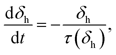 | (2) |
τ = B![[thin space (1/6-em)]](https://www.rsc.org/images/entities/char_2009.gif) exp(C/Tsc), exp(C/Tsc), | (3) |
II. Model
SGMs are thermodynamically out-of-equilibrium materials. Every material which is not at thermodynamic equilibrium has a natural tendency to approach the thermodynamic equilibrium state.49 However, in order to facilitate such an approach, the microscopic constituents of the SGMs need to be sufficiently mobile (thermal energy). Typically, the soft materials are exposed to constant P (pressure) and constant (controlled) T conditions. In addition, by virtue of the incompressible nature of the same, these materials also do not undergo any change in υ (specific volume) as a function of time. Under such conditions, the equilibrium state in these materials can be characterized by the minimization of either the Gibbs (g) or Helmholtz (a) free energy.49 Since g = a + Pυ, when P and υ are constants, the minimization of g and a are equivalent. Therefore, in the analysis below we discuss this scenario only in terms of free energy. In the process of aging, under quiescent conditions, the structure of an arrested soft material undergoes spontaneous evolution such that it progressively attains lower free energy as a function of time.Typically in SGMs solid to liquid transition occurs upon application of a strong deformation field, a process typically known as rejuvenation or shear melting. The completely shear melted samples, immediately after the shear melting is stopped, can be considered to possess the highest free energy: g0. On the other hand, the minimum value of free energy is associated with that of the thermodynamic equilibrium state and is given by: g∞. If the decrease in free energy (g) with respect to time is assumed to be a first order process, we get:
 | (4) |
![[t with combining tilde]](https://www.rsc.org/images/entities/i_char_0074_0303.gif) = t/τ0 is dimensionless time and
= t/τ0 is dimensionless time and ![[small tau, Greek, tilde]](https://www.rsc.org/images/entities/i_char_e0e5.gif) = τ/τ0 is dimensionless relaxation time, where τ0 is the relaxation time of a soft glassy material in its completely rejuvenated state (ϕ = 1). In eqn (4), we assume that the rate of change in free energy is proportional to the excess free energy divided by the time scale of structural rearrangement [(ϕ)] in a material. This time scale is equivalent to the relaxation time of a material, which is suggestive of the mobility of the constituents in a material at any given ϕ. As mentioned before, any material which is out of thermodynamic equilibrium, aspires to achieve the thermodynamic equilibrium. However, a material can be driven out of thermodynamic equilibrium in a trivial sense by perturbing an equilibrium material to high energy states. The consequent response that establishes equilibrium is merely transient and not physical aging if the relaxation time is constant. As suggested by Fielding and coworkers,38 for any process to qualify as physical aging, its relaxation time must increase during the time over which the relaxation takes place. Consequently, (ϕ) must be a decreasing function of ϕ. In SGMs, while physical aging indeed causes a decrease in free energy as a function of time, we cannot associate any thermodynamically measurable variable with a decrease in free energy. Furthermore, SGMs have a variety of different microstructures that demonstrate remarkably similar forms of the dependence of relaxation time on aging time. It is therefore no surprise that no empirical or other relation is available in the literature to relate the structure to free energy and in turn to the relaxation time in SGMs.
= τ/τ0 is dimensionless relaxation time, where τ0 is the relaxation time of a soft glassy material in its completely rejuvenated state (ϕ = 1). In eqn (4), we assume that the rate of change in free energy is proportional to the excess free energy divided by the time scale of structural rearrangement [(ϕ)] in a material. This time scale is equivalent to the relaxation time of a material, which is suggestive of the mobility of the constituents in a material at any given ϕ. As mentioned before, any material which is out of thermodynamic equilibrium, aspires to achieve the thermodynamic equilibrium. However, a material can be driven out of thermodynamic equilibrium in a trivial sense by perturbing an equilibrium material to high energy states. The consequent response that establishes equilibrium is merely transient and not physical aging if the relaxation time is constant. As suggested by Fielding and coworkers,38 for any process to qualify as physical aging, its relaxation time must increase during the time over which the relaxation takes place. Consequently, (ϕ) must be a decreasing function of ϕ. In SGMs, while physical aging indeed causes a decrease in free energy as a function of time, we cannot associate any thermodynamically measurable variable with a decrease in free energy. Furthermore, SGMs have a variety of different microstructures that demonstrate remarkably similar forms of the dependence of relaxation time on aging time. It is therefore no surprise that no empirical or other relation is available in the literature to relate the structure to free energy and in turn to the relaxation time in SGMs.
In particulate suspensions, an increase in the volume fraction (φ) of the suspended particles, which curbs the mobility of the same, is also known to cause an increase in relaxation time (τ). The corresponding relation between τ and φ was proposed by Krieger and Dougherty,50 which has been extensively used in the literature and has been experimentally validated for a variety of suspension systems.37 Furthermore, mode coupling theory (MCT), which predicts the onset of glass transition in colloidal glasses well, also employs an identical functional form to that of Krieger and Dougherty.37 In both the forms τ of suspension diverges according to a power law (τ ∼ [1 − (φ/φ*)]−B) as φ approaches a certain threshold φ* associated with random close packing. On the other hand, in aging glassy materials, under a constant concentration of constituents, the mobility decreases continuously due to a decrease in free energy. In this work, we therefore propose a relation between relaxation time and free energy, which has an equivalent functional form to that proposed by Krieger–Dougherty or in MCT. In the case of some SGMs, including suspensions of particles with hard sphere interactions, the relaxation time may diverge for values of free energy above the minimum (nonzero values of ϕ). If such values of free energy are denoted by ϕ* (at which the constituents do not possess mobility to facilitate relaxation), a generic form of the proposed expression is given by:
 | (5) |
= 1 at ϕ = 1, f(ϕ) = 0 at ϕ = 1. Eqn (4) can be solved using eqn (5) to yield: | (6) |
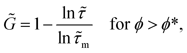
For various values of β, and for any arbitrary functional form of f(ϕ) that satisfies the above two conditions, is expected to show a stronger than linear, weaker than linear or linear dependence on according to eqn (6). Eqn (4) suggests that when is stronger than linear, must diverge before the system reaches the equilibrium state (ϕ* > 0). On the other hand, for a linear or weaker relationship the system must approach the equilibrium state in the limit: → ∞. Eqn (6), therefore, suggests that the value of β is directly related to the strength of evolution of as a function of time, which in turn controls ϕ*. Furthermore, the above discussion imposes another constraint on f(ϕ): (3) at ϕ = 0, f(ϕ), ϕ* and β should assume values such that → ∞ in that limit (it is well known that for many SGMs including a suspension of concentrated monodispersed particles, the lowest free energy state is a crystal state for which the relaxation time is ∞. Therefore, for all those materials wherein aging results in acquiring the lowest free energy state, diverges as the equilibrium state is approached: → ∞ in the limit of ϕ = 0). We propose the following functional form that satisfies all of the above constraints given by:
| f(ϕ) = lnϕ. | (7) |
on under quiescent conditions.
The initial condition to solve eqn (6) can be represented as: ϕ = ϕsm (or = (ϕsm)) at = 0, that is the moment shear melting is stopped (in principle, if shear melting tends to rejuvenate the material completely, ϕsm = 1 (or = 1); however as shown below such a possibility exists only if shear melting is carried out at shear rates → ∞). Assuming A = (1 − β)/lnϕ*, the solution of eqn (6) for a mentioned initial condition is given by:
| = [(ϕsm) + A]μ, | (8) |
≫ 1), to give:| ≈ (A)μ, A ≫ 1. | (9) |
In dimensional form eqn (9) is represented by: τ ≈ Aμτ0(t/τ0)μ. Interestingly, the relaxation times of many glassy materials, which include soft, molecular and spin glasses, demonstrate a power law dependence on time given by eqn (9).24,28,38,41,51,52 It is therefore interesting to see that the proposed relation between and ϕ given by eqn (5) with an assumption of eqn (7) leads to an experimentally observed power law dependence. It should be noted that values of μ < 1 represent sub-aging, μ > 1 represent hyper-aging, while μ = 1 represents a full aging scenario.1,2Eqn (5) can be rewritten in terms of μ and A as:
 | (10) |
 | (11) |
| = ϕ−A, μ = 1. | (12) |
→ ∞ as ϕ → ϕ*, where ϕ* is given by:| ϕ* = exp(1/A(1 − μ)) for μ > 1, | (13) |
Among various power law dependencies represented by eqn (10)–(12), the linear dependence of relaxation time on waiting time (μ = 1) has important practical significance. Firstly, the linear dependence is observed experimentally for a very broad class of SGMs in the absence of a deformation field. Such a dependence is also observed for molecular as well as spin glasses.41,52 In addition, from a scaling point of view it is often argued that in the absence of any externally dominating time scale, which is a typical case in glassy materials, the only naturally available imposed time scale is the waiting time, which is the time elapsed since either thermal quench (molecular glasses) or mechanical quench/shear melting (SGMs).19 Consequently the relaxation time scales as the waiting time. In the literature, however, various SGMs have been reported to show sub-aging (μ < 1) or hyper-aging (μ > 1) behavior.26,29 Such behavior can originate from the imposition of another field on a material, which tends to increase or decrease the characteristic timescale of a material beyond that which can be achieved by merely a physical aging process. In the case where the process of time dependent decrease in free energy is not entirely physical, but partly chemical so that it is irreversible, the material tends to show hyper-aging dynamics.29,53
It is usually observed that in an aging process, the modulus of the glassy material either remains constant or increases as a function of time. However, even in the latter case, the enhancement in the modulus is usually not as spectacular as that of the relaxation time. The scaling argument suggests that if E is the average depth of the energy wells in which the constituents of a soft glass are arrested, the modulus can be represented as the energy density: G = cE/b3, where b is the characteristic length-scale (such as average inter-particle distance or network length) associated with a material and c is the constant of proportionality.46 Consequently, if E remains constant throughout the aging process, the modulus of a material will remain constant even if the relaxation time shows an increase as per eqn (9). Such a possibility arises if the aging behavior of a system is purely entropic. Such a scenario is observed for particulate colloidal glasses with hard sphere interactions, wherein the energy is identical for all of the states, and aging is controlled by maximization of entropy (s). Such a case can also be equivalently represented by minimization of the free energy as: g = h − Ts, as for entropic systems h is constant throughout the aging process under isothermal and isobaric conditions. Therefore, for purely entropy controlled aging systems the modulus can be represented as:
![[G with combining tilde]](https://www.rsc.org/images/entities/i_char_0047_0303.gif) = 1, = 1, | (14) |
= G/G0 is the dimensionless modulus and G0 is the constant modulus.
For materials wherein the constituents share energetic interactions with each other, the mean energy well depth E increases as a function of time. In the limit of either equilibrium state (ϕ → 0) or high free energy ‘frozen’ state (ϕ → ϕ*), E saturates to a constant value E*. In the regime where E increases as a function of time, we assume that the mean relaxation time has an Arrhenius dependence on E, given by: τ = τmexp(E/kBT), where τm is the microscopic relaxation time.38 However as ϕ → ϕ* or ϕ → 0, the relaxation time no longer obeys an Arrhenius relationship, as even though → ∞, E saturates to a finite value E*. Such behavior is often observed for molecular glasses, wherein the relaxation time dependence deviates from Arrhenius-to-MCT-to-Vogel–Fulcher as the glass transition is approached.37 Consequently, in a limit where the Arrhenius relation is obeyed (for ϕ > ϕ* ≥ 0), the dependence of the modulus on relaxation is easily obtained as:
 | (15) |
m = τm/τ0 (it should be noted that m < 1 as discussed below, while ≥ 1), = G/G0 is the dimensionless modulus where G0 is the modulus associated with the state: ϕ = 1, and is given by: G0 = −(ckBT/b3)lnm. However, as the frozen state is approached (ϕ → ϕ*), the modulus saturates to a finite value while → ∞.
Application of the deformation field increases ϕ. We assume that the rate of increase of ϕ is directly proportional to the rate of strain (V) associated with the viscous (dissipative) flow weighted by 1 − ϕ. Here V is the second invariant of the rate of strain tensor ![[small gamma, Greek, dot above]](https://www.rsc.org/images/entities/b_i_char_e0a2.gif) V associated with the viscous flow, given by:
V associated with the viscous flow, given by:  54 Consequently, eqn (4) can be modified for evolution under the application of a deformation field as:
 | (16) |
 is the strain rate in a dimensionless form. Eqn (16) is the evolution equation for ϕ under the application of a deformation field. The strain rate associated with viscous flow can be directly related to the stress tensor as: σ = ηV. Viscosity η = Gτ is a product of the relaxation time and modulus, which can be represented by eqn (10)–(12) and eqn (14) or (15), respectively. For a simple shear flow field eqn (16) can therefore be modified to:
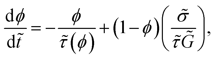 | (17) |
![[small sigma, Greek, tilde]](https://www.rsc.org/images/entities/i_char_e10d.gif) = σ/G0 is the dimensionless shear stress.
= σ/G0 is the dimensionless shear stress.
Usually soft glassy materials are viscoelastic in nature. We can, therefore, use a single mode Maxwell model, which is the simplest constitutive equation for a viscoelastic material. For a time dependent modulus and viscosity a single mode Maxwell model is given by:
 | (18) |
E) in the opposite direction (negative) due to an increase in the modulus or due to recovery. In this case, although E has a negative sign (assuming σ to be positive or zero) its second invariant will always have a positive sign. However, physically such a reverse strain rate cannot cause rejuvenation in a material, further justifying the usage of only the viscous component of the strain rate in eqn (16).
Eqn (16) in a rate controlled form, or eqn (17) in a stress controlled form, is the proposed expression for the evolution of ϕ. On the other hand, eqn (18) is the constitutive equation associated with the model. Furthermore, we assume that the relation: = (ϕ) represented by eqn (10)–(12) is intrinsic in nature and is independent of the nature and the strength of the deformation field. Therefore, the deformation field affects the evolution of relaxation time only through its dependence on ϕ. As discussed before, under quiescent conditions (no deformation field), of a material shows a power law dependence on as observed experimentally. Under the application of a deformation field, however, ϕ is expected to decrease or increase leading to an increase or decrease in .
Interestingly, the evolution of ϕ expressed by eqn (16) can be transformed into a generic functional form given by eqn (1) proposed by Coussot.34 Multiplying eqn (16) by /ϕ leads to eqn (1) with λ = ∫(/ϕ)dϕ and Q = (1 − ϕ)/ϕ. However, unlike various previous approaches that employ arbitrary functional forms for Q = Q(λ) and η = η(λ), the present model only needs the expression of given by eqn (5), which has been derived from physical arguments and complies with the experimental observations under quiescent conditions. For systems whose modulus increases with , the present model has three parameters in a dimensionless form that are physically meaningful. The first is the rate of aging μ, the second is the constant A (which is equal to [(1 − μ)lnϕ*]−1), and the third is τm. However, if the modulus is constant the model needs only the first two parameters: μ and A, which are the characteristics features of an SGM that depend upon the microstructure of the same. Most importantly μ and A can be estimated experimentally by knowing the dependence of the relaxation time on aging time and have the following constraints: μ ≥ 0 and A > 0. Such dependence can be very easily obtained by carrying out creep or stress relaxation experiments at different aging times as discussed in the literature.15,24,27,51,55 In the present model, the microscopic relaxation time (τm) determines the rate at which the modulus evolves with time. Eqn (15) suggests that the smaller the value of τm is, the weaker is the evolution of . In the limit of ϕ = 1, if the mean depth of the energy wells occupied by the constituents of SGM is E0, an Arrhenius relation leads to a relaxation time of that state as: τ0 = τmexp(E0/kBT), which leads to: m = exp(−E0/kBT). Although E0 is the shallowest mean energy depth possible for ϕ = 1, it is always positive. Consequently, m must vary in the limit: 0 < m < 1. (It is important to note that even though as per eqn (15) it appears that in the limit of τm = 0 the modulus remains constant, such a limit exists only if there is no aging. This is because the microscopic relaxation time τm is a unit of time at which a material ages. Even for a material wherein aging is purely entropic, the modulus is constant and τm is nonzero. This is because in such a case the relaxation time does not depend on the energy well depth.)
III. Results
To begin with we shall discuss the results associated with the steady state predictions. In the limit of steady state, sinceE = 0, eqn (16) leads to expressions for the steady state strain rate given by: | (19) |
 | (20) |
ss = (ϕss) given by eqn (10)–(12) and ss = ss(ϕss)). As expected, the steady state relationship between and  is simply:
 | (21) |
![[small eta, Greek, tilde]](https://www.rsc.org/images/entities/i_char_e110.gif) = ssss. In Fig. 1(a) we plot ss as a function of
= ssss. In Fig. 1(a) we plot ss as a function of  for materials that show an enhancement in modulus as a function of time for different values of μ at A = 10 and m = 0.1. It can be seen that the dependence of ss on
  is monotonic for μ = 1 over an explored region, however it becomes non-monotonic with the presence of a minima for the higher values of μ. The region where ss decreases with an increase in
  is known to be unstable.56 In Fig. 1(b) we also plot ss with respect to ϕ by solving eqn (20) for A = 10 and m = 0.1 for different values of μ, which also show non-monotonic relationships except for μ = 1. In the inset of Fig. 1(b) we plot the relation between ss and ϕ for μ = 2 but different values of A and m. It can be seen that with an increase in μ and A, the curves shift to greater values of ss and also shift ϕc (the value of ϕss associated with the minimum in ss) and ϕ* (according to eqn (13)) to higher values. The inset also shows the behavior of the steady state curve at two values of m = 0.1 and 0.001. The increase in m shifts the location of the minima as well as the curve to higher values of ss. As is apparent from eqn (19)–(21), the qualitative dependence of ss on
  is similar to that between ss and ϕss with the minimum in ss in the former relation coinciding with that of the latter.
 | ||
Fig. 1 Relationship between ss and (a)  , (b) ϕ given by eqn (19) and (20) for different values of μ for A = 10 and m = 0.1. From bottom to top μ = 1, 2, 3, 4 and 5. In the inset of (b) ss is plotted against ϕ for μ = 2 and different values of A and m; while for a dotted line: m = 0.001 and A = 0.9. For full lines from top to bottom: m = 0.1 and A = 30, 10, 2.5, 1.5, and 0.9. In all of the plots the part of the curves having a negative slope is an unstable region. The non-dimensional strain rate, stress and free energy associated with the minimum of the curve are represented by , (b) ϕ given by eqn (19) and (20) for different values of μ for A = 10 and m = 0.1. From bottom to top μ = 1, 2, 3, 4 and 5. In the inset of (b) ss is plotted against ϕ for μ = 2 and different values of A and m; while for a dotted line: m = 0.001 and A = 0.9. For full lines from top to bottom: m = 0.1 and A = 30, 10, 2.5, 1.5, and 0.9. In all of the plots the part of the curves having a negative slope is an unstable region. The non-dimensional strain rate, stress and free energy associated with the minimum of the curve are represented by  , c and ϕc, respectively. , c and ϕc, respectively. | ||
In order to obtain the values of the parameters μ, A and m for which flow curves become non-monotonic we solve  by differentiating eqn (21) by
  leading to:
 | (22) |
For a material with a time dependent modulus, the numerical solution of eqn (22) gives ϕc from which  and c (presented in Fig. 1) can be obtained by using eqn (19) and (20), respectively, for ϕss = ϕc. In Fig. 2(a) and (b) we plot
  , c and ϕc as a function of μ for various values of A and m for a time dependent modulus given by eqn (15). It can be seen that, irrespective of the values of A and m, all the three variables:
  , ϕc and c decrease with a decrease in μ; and tend to zero as μ approaches 1. An increase in A as well as m, on the other hand, shifts all of the curves to higher values of the respective ordinates. In Fig. 2(b) we also plot ϕ*, which is the minimum attainable value of ϕ (presented in Fig. 1) given by eqn (13) with respect to μ for different values of A. There is no steady state associated with the values of ϕ in the range ϕ* ≤ ϕ < ϕc as it is an unstable branch. It can be seen that the width of the unstable region represented by ϕc − ϕ* decreases with an increase in A as well as μ (in the limit of μ → 1, both ϕc and ϕ* approach zero). Furthermore, eqn (13) clearly shows that ϕ* is independent of m. Fig. 2(b) also shows that with a decrease in m, ϕc decreases, and it can be shown from eqn (15) and (22) that in the limit of m ≪ 1, ϕc → ϕ*. Importantly Fig. 2 clearly indicates that the steady state stress–strain rate relationship is monotonic for μ ≤ 1.
 | ||
Fig. 2 (a) Dimensionless critical strain rate  and stress (c) (shown in inset) are plotted as a function of μ. The full lines represent different values of A (from top to bottom: 30, 10, 2.5, 1.5, and 0.9.) and m = 0.1. In (b) ϕc (full lines) and ϕ* (dashed lines) [eqn (13)] are plotted as a function of μ. From top to bottom A = 30, 10, 2.5, 1.5, and 0.9. The dotted line in both the figures is for A = 0.9 and m = 0.001. and stress (c) (shown in inset) are plotted as a function of μ. The full lines represent different values of A (from top to bottom: 30, 10, 2.5, 1.5, and 0.9.) and m = 0.1. In (b) ϕc (full lines) and ϕ* (dashed lines) [eqn (13)] are plotted as a function of μ. From top to bottom A = 30, 10, 2.5, 1.5, and 0.9. The dotted line in both the figures is for A = 0.9 and m = 0.001. | ||
Now we consider a case when = 1 during aging, for which eqn (22) clearly indicates that the dependence of ss on  does not show a minimum (ϕc does not exist in the range: 0 ≤ ϕ≤ 1). Consequently, for μ ≤ 1 the dependence of ss on
  must show a monotonic increase. For μ > 1, according to eqn (10) and (13), → ∞ as ϕ → ϕ*. As a result as
  in the limit of → ∞, stress must show a plateau at:
 | (23) |
y is the yield stress. In Fig. 3 we plot ss as a function of  for different values of μ and A at = 1. An observed plateau in ss in the limit of
  indicates the presence of permanent yield stress that is independent of time (non-thixotropic yield stress). As shown in Fig. 3, y can be seen to be increasing with μ as well as A as per eqn (23).
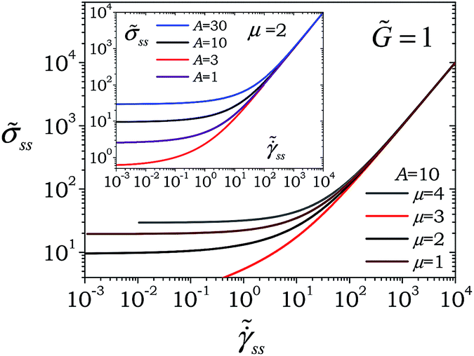 | ||
Fig. 3 Relationship between ss and  given by eqn (19) and (20) for different values of μ (from top to bottom μ = 4, 3, 2 and 1) for A = 10 for a case when the modulus remains constant = 1. It can be seen that for μ > 1, ss shows a plateau in the limit of given by eqn (19) and (20) for different values of μ (from top to bottom μ = 4, 3, 2 and 1) for A = 10 for a case when the modulus remains constant = 1. It can be seen that for μ > 1, ss shows a plateau in the limit of 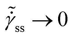 demonstrating the presence of constant yield stress. In the inset ss is plotted against demonstrating the presence of constant yield stress. In the inset ss is plotted against  for μ = 2 and different values of A (from top to bottom, A = 30, 10, 3 and 1). It can be seen that the yield stress increases with μ and A according to eqn (23). for μ = 2 and different values of A (from top to bottom, A = 30, 10, 3 and 1). It can be seen that the yield stress increases with μ and A according to eqn (23). | ||
The presence of yield stress is also characterized by a non-monotonic flow curve, such as that shown in Fig. 1, as there are no steady state values of strain rate  associated with stresses smaller than that corresponding to the minimum represented by c. This concept is described by Fig. 4, wherein we plot ss as a function of
  for A = 10, m = 0.1 and two values of μ: μ = 1 (Fig. 4(a)) and μ = 2 (Fig. 4(b)). We also plot the corresponding values of ϕss on the abscissa. Let us consider a case wherein subsequent to complete shear melting (ϕ = 1), a material is allowed to evolve without applying stress ( = 0). Such evolution is carried out, wherein ϕ decreases as a function of time (according to eqn (16) with
  ), until it reaches a certain value of ϕ = ϕi (initial value of ϕ) at which stress is applied. In Fig. 4(a), we consider a case wherein = 6 is applied to a material. Consequently, if ϕi is in region II, where dϕ/d < 0, ϕ will continue to decrease until it reaches the steady state value associated with the intersection of ss = 6 and the flow curve. If ϕi is in region I, where dϕ/d > 0, ϕ will increase until it reaches the steady state value associated with ss = 6. However, since the flow curve is monotonic, a material will flow irrespective of the value of applied stress (the scenario for a material with constant modulus will be similar to that discussed for Fig. 4(a) as the curves shown in Fig. 3 are also monotonic apart from the fact that they depict a plateau associated with permanent yield stress).
 | ||
| Fig. 4 Steady state flow curves are shown for (a) A = 10, m = 0.1 and μ = 1 and (b) A = 10, m = 0.1 and μ = 2. The corresponding values of ϕss are also shown on the inside part of an abscissa. For a monotonic flow curve a material will yield irrespective of the value of stress. For a non-monotonic flow curve, the application of stress σc on a material will cause yielding (flow) only if ϕi > ϕc. In addition, if ϕi is in the range ϕ* < ϕi < ϕc, the application of stress will cause flow only if dϕ/d, given by eqn (17), is positive. Both the figures are discussed in detail in the text. | ||
For Fig. 4(b), let us assume the applied stress is = 40. In this case the steady state value of ϕ is the one associated with the intersection of ss = 40 and the increasing part of the flow curve. If ϕi is in region III, where dϕ/d < 0, ϕ will continue to decrease until it reaches the steady state value. If ϕi is in region II, where dϕ/d > 0, ϕ will increase until it reaches the steady state value. Therefore, for a given applied stress greater than c, if ϕi lies in regions II and III, a material will eventually attain a steady state. However, if ϕi is in region I where dϕ/d < 0, ϕ will continue to decrease even under application of the stress field until it attains the minimum possible value of ϕ*. Consequently a material will not attain the steady state.
The presence of a non-monotonic flow curve as shown in Fig. 4(b) therefore leads to a natural dependence of yield stress on ϕ given by:
| y = c for ϕi ≥ ϕc | (24) |
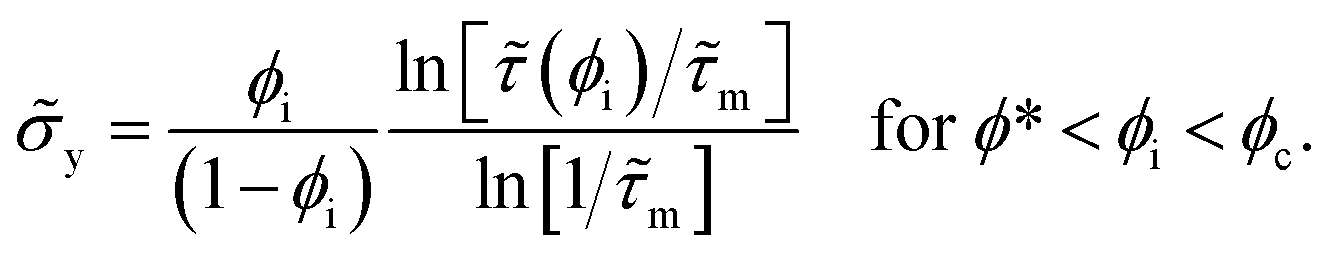 | (25) |
Since ϕi decreases with time, the yield stress y will first remain constant for ϕi ≥ ϕc as shown by eqn (24), and then increase with time for ϕ* < ϕi < ϕc as per eqn (25). In Fig. 5 we plot variation of y with for different values of A, m and μ. It can be seen that y is constant at short times and subsequently shows a logarithmic dependence on . In addition, the dependence of y on becomes stronger with an increase in all of the three variables: A, m and μ. As explained in Fig. 4(b) and as described by eqn (17) and (25), we can propose a thixotropic yielding criterion: upon application of stress σ on a material in a momentary state ϕi, if ϕ continues to decrease towards ϕ* the material will not yield. On the other hand, if the application of stress causes evolution (increase or decrease) of ϕ so that it stabilizes at a value equal to or above ϕc, the material will yield.
 | ||
| Fig. 5 Evolution of dimensionless yield stress is plotted as a function of time for various values of μ for A = 10 and m = 0.1. The dashed line is for μ = 2 and m = 0.001. The inset shows evolution of y for different values of A at μ = 1.5 and m = 0.1. | ||
As described by eqn (17), whether a material yields or not, physical aging is affected by the strength of the stress field. Time evolution of relaxation time under a stress field can be obtained by manipulating eqn (10)–(12) and (16), and is given by:
 | (26) |
= 0, relaxation time dependence described by eqn (8) is recovered (μt = μ). As discussed before, let us consider a case wherein a material is allowed to age without applying stress, such that ϕ spontaneously decreases as per eqn (4), and at ϕ = ϕi stress is applied to the material. If ϕi ≥ ϕc, the term in braces is simply the reciprocal of ss(ϕss = ϕ) (obtained by replacing ϕss in eqn (20) by ϕ). Therefore, eqn (26) can be expressed in a simpler format: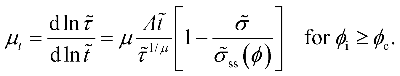 | (27) |
Consequently, if ϕi ≥ ϕc and > c, with an increase in time ss tends to so that μt must approach zero, enabling a material to achieve steady state. For the various values of parameters for which ϕc does not exist according to eqn (22), the evolution of relaxation time is given by either eqn (26) or (27). We present the former case in Fig. 6(a) wherein we plot and μt as a function of time for μ = 1, ϕi = 0.96 (corresponding ss = 28.3) for different values of . It can be seen that for = 0, shows a continuous increase and correspondingly μt approaches 1 in the limit of long times. Furthermore, for nonzero stresses, if < ss the evolution of weakens from the point of application of leading to a step decrease in μt. The corresponding evolution of , however, eventually plateaus out to a constant value causing μt to approach 0 after showing a maximum. If > ss, decreases eventually leading to a plateau value and demonstrating negative values of μt before μt → 0. In Fig. 6(b) we also explore the evolution of and μt for a system with a constant modulus ( = 1), μ = 2, and ϕi = 0.906 (correspondingly y = 9.5, which is constant) for different values of by solving eqn (8) and (27). For = 0, the evolution of , as per eqn (8) with ϕsm = 1, attains μt = 2 in the limit of long times. However, for < y, increases with time but with a weaker dependence and the corresponding μt approaches μ in the limit of long times. Furthermore, since the flow curve for = 1 is monotonic, for y < < ss the behavior of and μt with respect to is expected to be qualitatively similar to that shown in Fig. 6(a) for < ss. For > ss > y, μt continues to decrease and shows a minimum before approaching a steady state value of 0.
 | ||
| Fig. 6 The temporal evolution of and μt is plotted for different values of for (a) A = 10, m = 0.1, and μ = 1 (the stress is applied when ϕi = 0.96 for which σss = 28.3). (b) The evolution of and μt is plotted for a system with = 1, A = 10, μ = 2, and permanent yield stress y = 9.5 (the stress is applied when ϕi = 0.906). The values of stress are shown in the legend. In part (c) the same variables are plotted for A = 10, m = 0.1 and μ = 2 (the stress is applied when ϕi = 0.906 for which y = 46.1). The corresponding positions of ϕi for (a) and (c) are described in Fig. 3(a) and (b), respectively, by dotted lines. | ||
For μ > 1 and in eqn (15), the flow curve is non-monotonic. For such a case if ϕi is such that: ϕ* < ϕi < ϕc, eqn (25) suggests that the term in braces is essentially y(ϕ). Consequently, eqn (26) can be rewritten as:
 | (28) |
We represent this scenario in Fig. 6(c) wherein the time dependent evolution of and μt is plotted for μ = 2, ϕi = 0.906 (corresponding y = 46.1) for different values of . If ≥ y(ϕi), y(ϕ) → causing μt → 0 enabling the material to attain a steady state. For < y(ϕi), continues to increase but with weaker dependence. The corresponding μt shows a step decrease at the point of application of stress, but increases subsequently. Very interestingly at moderately high times μt increases beyond μ = 2, and shows a maximum. Such behavior can be attributed to a decrease in ϕ as a function of time which leads to /y(ϕ) → 0 in the limit of long times. However, owing to impeded increase in τ due to applied , A/1/μ increases beyond unity causing μt to increase beyond μ. Nonetheless as ϕ → ϕ*, A/1/μ again decreases gradually.
The presence of yield stress in thixotropic materials (μ > 1), as shown in Fig. 4(c), on the one hand leads to the continuation of aging for < y. On the other hand, for ≥ y the material eventually undergoes rejuvenation producing a liquid phase. For such conditions, we plot the evolution of strain (γ) under the application of for ϕi in the domain ϕ* < ϕi < ϕc in the inset of Fig. 1S of the ESI.† It can be seen that for < y, γ increases but eventually reaches a plateau. However, for ≥ y, γ shows a sharp increase with time. Application of in the vicinity of y but slightly larger and smaller than y, can be seen to be following a very similar evolution to γ for a significant period of time. However, in the limit of very long times, γ bifurcates. This phenomenon is popularly known as viscosity bifurcation in the literature. For strain curves associated with ≥ y, we can define the time at the point of inflation d2γ/d2 = 0 as the time to yield (dy). In Fig. 1S of the ESI† we plot dy as a function of y. It can be seen that time dy rapidly increases as − y → 0. On the other hand, for ≫ y, dy decreases weakly with an increase in .
In Fig. 2S of the ESI,† we plot the evolution of γ at constant but at different ϕi. This plot is therefore equivalent to carrying out creep experiments at different waiting times after stopping the shear melting. It can be seen that for ϕi smaller than ϕss associated with = ss(ϕss), the system is in region I of Fig. 4(b), consequently the strain eventually reaches a plateau (the plateau is not apparent in Fig. 2S† as it occurs after a very long time). However, if ϕi is larger than ϕss, the application of = ss(ϕss) causes yielding, wherein strain can be seen to be rapidly increasing with time.
Another important characteristic feature of glassy materials in general and SGMs specifically is the presence of residual stresses. Typically SGMs are shear melted by applying a constant shear rate of sufficiently large magnitude prior to carrying out any rheological study. During shear melting a steady state is reached  and the corresponding ss and ϕss are given by eqn (19) and (20). Subsequent to the cessation of shear melting if the strain is kept constant, a decay in stress can be easily estimated by simultaneously solving eqn (16) and (18) with given by eqn (10)–(12) and initial conditions of = ss and
  at = 0, where
  is the dimensionless shear rate associated with shear melting. It should be noted that even though strain is kept constant resulting in = 0, E and V may not be constant leading to: E = −V. As stress relaxes, the spring in the Maxwell model contracts, giving rise to: V = (t)/, where (t) is an instantaneous stress remaining in a material as it relaxes. In Fig. 7 we plot as a function of for a material with a constant modulus ( = 1) with A = 10 and μ = 1.1, 1 and 0.9 for various values of ϕi in the range 0.95 and 0.65. It can be seen that the higher the value of ϕi is, the greater is the plateau value of in the limit of → 0. Furthermore, this value is independent of μ as per eqn (20). Fig. 7 shows that for μ = 0.9 stress decays to 0, while for μ = 1 stress shows a power law decay. For μ = 1.1, on the other hand, stress shows a plateau in the limit of high times describing the presence of residual stress. The most prominent feature of Fig. 7 is that irrespective of the initial value of stress, in the limit of long times all of the stress relaxation curves coincide for a given value of μ. Consequently, according to the present model, the residual stress is independent of the initial stress or state of a material.
 | ||
| Fig. 7 Relaxation of stress subsequent to cessation of shear melting for a material with a constant modulus ( = 1) for different values of shear melting shear rates sm (expressed in terms of ϕi) and μ for A = 10. For a given value of μ, in the limit of → 0 only depends on ϕi. In that limit, from top to bottom: ϕi = 0.95, 0.9, 0.85, 0.8, 0.75, 0.7, and 0.65. The corresponding sm depends on μ and can be obtained from eqn (19). In the limit of → ∞, stress shows a plateau for μ > 1, stress undergoes a power law relaxation for μ = 1, while stress decays to 0 for μ < 1. In the inset is plotted as a function of for μ = 1.1 for two values of ϕi = 0.95 and 0.65. The inset shows that greater initial stress leads to a faster relaxation of stress due to rejuvenation caused by dissipative deformation of the dashpot as a result of the contracting spring. | ||
In addition to the relaxation time, if the modulus of a material also shows an increase, the relaxation of stress shows some further interesting features. It is well known that an increase in the modulus of a spring having constant strain increases the stress induced in the same. Consequently, an increase in the modulus as a function of time impedes the relaxation of stress. In Fig. 8 we plot the relaxation of stress for μ = 1.1, 1 and 0.9 for different values of ϕi. Various features of the observed behavior are qualitatively identical to those for a material with a constant modulus (shown in Fig. 7) for μ ≤ 1. This suggests that irrespective of whether the modulus increases or not, stress must decay completely for μ ≤ 1. However, for μ = 1.1, at longer times the relaxation curves in Fig. 8 are observed to demonstrate a minimum, which can be attributed to a time dependent increase in the modulus. Nonetheless, as mentioned before, as the relaxation time diverges to ∞, the modulus must eventually reach a constant value. Consequently, the residual stress must also reach a constant value. In the inset of Fig. 8, we present a schematic wherein possible scenarios are described. Depending upon when the modulus becomes constant in relation to the increase in relaxation time, stress may or may not show a minimum before reaching a residual stress plateau in the limit of long times. In the limit of very short times, if the modulus shows enhancement, stress may also show an increase in that limit before beginning to relax. Although to best of our knowledge an increase in stress during stress relaxation of aging SGMs has not been reported in the literature, the present work clearly predicts such a possibility, particularly for those materials that show very a prominent increase in modulus as a function of time.
 | ||
| Fig. 8 Stress is plotted as a function of time for a material with a time dependent modulus given by eqn (15) for various model parameters as mentioned. For a given value of μ, in the limit of → 0 only depends on ϕi whose values are same as those mentioned in Fig. 7. It can be seen that since the modulus increases with time, the residual stress in the material with μ > 1 may show an increase at very long times. However, as shown in the inset since the modulus always remains finite, in the limit of long times the stress must show a plateau in that limit even if it shows an increase over a certain period. The inset also shows the possibility that at very early times for ≪ () a possible increase in modulus may show an early increase in stress. | ||
Subsequent to the cessation of shear melting, instead of keeping the strain constant, if stress is removed ( = 0) the material will undergo strain recovery. It is known that upon the removal of stress a single mode Maxwell model undergoes an instantaneous recovery.57 However, in real viscoelastic (including soft glassy) materials recovery occurs over a finite (and sometimes a prolonged) period of time. The period over which recovery takes place is controlled by the retardation timescale associated with a material. Therefore, in order to solve the strain recovery problem, we consider a dashpot (with viscosity ηd) in parallel with the spring. Consequently, the corresponding Voigt element (spring and dashpot in parallel) will have a retardation time given by: τd = G/ηd, where G is the modulus associated with the spring. It should be noted that in addition to the Voigt element there also exists a dashpot with viscosity η in series (same as that of the Maxwell model), by virtue of which the system also has a relaxation time (τ = G/η). However, this series dashpot does not play any role during recovery as the deformation of the same is always permanent, consequently 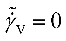 . We assume that τd represents the average retardation time of a material, whose average relaxation time is τ. However, if the relaxation time undergoes a time dependent evolution according to eqn (8), causality demands that the retardation time must also show an identical time dependence.53 As a result, the mean retardation time is given by:53
| d = α, | (29) |
d = τd/τ0. The elastic strain recovery upon the removal of stress subsequent to the cessation of shear melting with initial conditions: at = 0, γ = γsm = ss/ss and  is given by:
 | (30) |
 | (31) |
 | (32) |
The ultimate recovered strain (γ∞) can be obtained from eqn (30)–(32) in the limit of → ∞ and is given by:
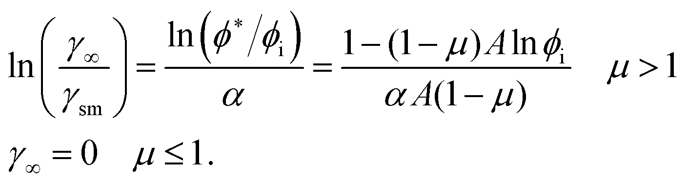 | (33) |
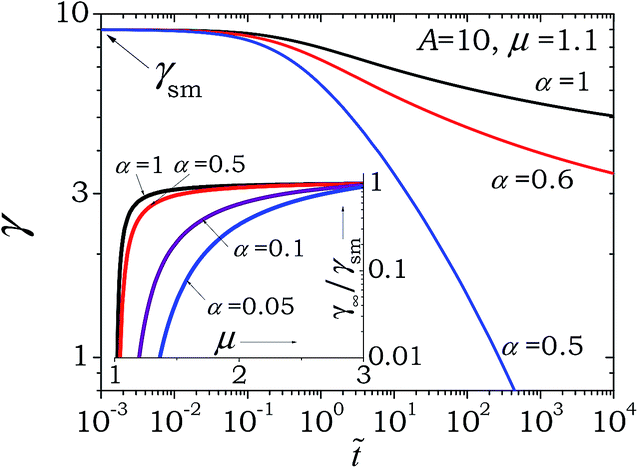
In Fig. 9 we plot (γ − γsm)/γsm as a function of for three values of μ and two values of ϕi as represented by eqn (30)–(32). In the inset we plot identical data in terms of the time dependent recovery of γ. It can be seen that for μ ≤ 1 the total elastic strain γsm indeed gets recovered in the limit of long times. However for μ > 1 only part of the elastic strain gets recovered leading to the presence of residual elastic strain in a material. This is because; owing to aging, the average retardation time of a material diverges converting the dashpot, which is in parallel with the spring, into a rigid rod preventing any further recovery of the spring. In Fig. 10 we plot the effect of average retardation time, by varying factor α, on the recovery behavior. It can be seen that a decrease in α, which corresponds to a decrease in retardation time at any fixed aging time, causes the magnitude as well as the rate of recovery to increase. In the inset we plot γ∞/γsm as a function of μ, which clearly shows that the larger the value of μ or α is, the smaller is the ultimate recovered strain (γ∞). Interestingly in the limit of α → 0 all of the elastic strain is expected to undergo an instantaneous recovery irrespective of the value of μ.
 | ||
| Fig. 9 Evolution of (γ − γsm)/γsm is plotted for various values of μ and ϕi. In the inset identical data is plotted for the elastic strain present in a material as a function of time. It can be seen that for μ ≤ 1 the entire elastic strain is recovered in the limit of long times, however for μ > 1 residual elastic strain remains in a material. | ||
 | ||
| Fig. 10 Elastic strain present in a material is plotted as a function of time for different values of α. It can be seen that an increase in α increases the rate at which strain is recovered. In the inset normalized ultimate elastic strain (residual strain) is plotted as a function of μ, which shows that γ∞ increases with both α and μ. | ||
IV. Discussion
The most prominent result of the proposed model is that for a material with a time dependent modulus for μ > 1, the steady state relation between stress and strain rate is non-monotonic. On the other hand, for a constant modulus with μ > 1 a material shows a plateau of constant stress in the limit of small strain rate, while for μ ≤ 1 the steady state flow curve is always monotonic. We believe that these results are not limited only to the power law dependence of the relaxation time on waiting time. Any dependence between the relaxation time and waiting time, which is stronger than linear, must show a behavior similar to that observed for μ > 1. Conversely, any dependence which is weaker than linear should result in monotonic dependence between the steady state stress and strain rate. The non-monotonic relation between stress and strain rate for the present model gives rise to thixotropic yield stress. As described in Fig. 5, the yield stress remains constant until ϕi becomes larger than ϕc, below which it shows a logarithmic dependence on time. Recently Negi and Osuji58 measured the yield stress and yield strain of a 4 day old 3.5 weight % aqueous suspension of Laponite. They observed that the yield stress indeed showed a constant value for a certain period of time beyond which it showed a logarithmic increase with time. Interestingly, the relaxation time of the studied Laponite suspension showed an exponential dependence on waiting time over the same period for which constant yield stress was observed. At higher times the Laponite suspension showed a power law dependence on waiting time with μ ≈ 1.8. The yield stress in the corresponding regime showed a logarithmic increase with respect to waiting time. According to the present model it appears that for the Laponite suspension studied by Negi and Osuji,58 the relaxation time followed two different dependencies on ϕ: for ϕ > ϕc, τ = τ(ϕ) leads to τ ∼ exp(t/τ0), while for ϕ < ϕc, τ = τ(ϕ) leads to τ ∼ (t/τm)μ. Consequently, similar to the results shown in Fig. 5, the model is indeed expected to predict a constant value of yield stress for ϕ > ϕc followed by a logarithmic increase. It is important to note that the logarithmic increase in the modulus during aging as predicted by the present model using a scaling relation, which in turn is responsible for the logarithmic increase in yield stress, has been observed for many SGMs.32,51,59Negi and Osuji58 also observed that the yield strain decreases in the regime where yield stress is observed to be constant (for short times). On the other hand, the yield strain is observed to be constant in the limit of long times when the yield stress is observed to increase logarithmically. In the present model, considering the yield strain to be: γy = y/, its dependence on can be directly written as:
 | (34) |
 | (35) |
. On the other hand, for ϕ* < ϕi < ϕc, in the limit of long times the term in the braces in eqn (35) tends to 1, leading to a constant value of γy. Overall, the present model explains the yielding behavior of the Laponite suspension reported by Negi and Osuji58 very well.
It is well known that any material that possesses yield stress shows shear banding in a flow field with a gradient of shear stress. The axial flow of yield stress fluid in a pipe is a classic textbook example of shear banding.54 However, even in the absence of a shear stress gradient, a material with a non-monotonic steady state relationship between σss and ss, which is observed for μ > 1, demonstrates (thixotropic) shear banding if the imposed shear rate is less than c (refer to Fig. 4(b)). This is because a negative slope of σss − ss dependence is constitutionally untenable, consequently ss does not exist below c. Let us consider a case of simple shear flow in between parallel plates separated by distance H. If the top plate velocity V is such that V/H < c, shear banding will take place so that a band (or bands) having a (total) thickness h = V/c will flow with c. On the other hand, a band (or bands) with a total thickness H − h will remain stationary. An increase in V will decrease the width of the stationary band(s) and in the limit of V/H = c, the entire sample will flow with a shear rate c. The present model very clearly suggests that thixotropic shear banding is possible only when μ > 1 and increases sufficiently strongly so that the solution of eqn (22) causes ϕc to lie in the range: ϕ* < ϕc < 1. Remarkably, it is indeed observed that a simple concentrated emulsion which shows negligible enhancement in the modulus does not show thixotropic shear banding, but a clay loaded emulsion which shows significant enhancement in the modulus does show thixotropic shear banding13 as suggested by the present model. Interestingly Bécu et al.60 suggested that in a simple concentrated emulsion, if attractive interactions are induced, it shows thixotropic shear banding. Although Bécu et al.60 did not measure the modulus, we believe that attractive interactions will indeed induce evolution of the modulus in accordance with the present model. Experimentally such behavior has also been observed for a variety of SGMs such as suspensions of charged particles including smectite clay61–63 and cement paste,63 for which not only μ is expected to be greater than unity but the modulus also shows prominent increase as a function of time. The present work therefore also suggests that polymeric materials undergoing crosslinking reactions, wherein the relaxation time shows a stronger that linear dependence on time and the modulus shows a prominent increase,53 should also demonstrate shear banding.
The very fact that the steady state relation between stress and strain rate is monotonic for μ ≤ 1 implies an absence of thixotropic yield stress. Consequently, a material with μ ≤ 1 must yield for any value of applied stress. However, as is apparent from Fig. 6(a), even with μ ≤ 1, the smaller the stress is the longer time it takes to stop the enhancement of relaxation time. In practice, the yield stress is estimated by applying a linear or oscillatory stress ramp. Since stress increases from a small value to a large value over a finite time, at a certain stress a material shows a sudden enhancement in strain. As a result, the material shows an apparent yield stress, which is greater than zero. This behavior, therefore, may manifest itself as undergoing weak flow below a certain stress and strong flow above a certain stress, thereby resulting in so called “engineering yield stress.” Furthermore, engineering yield stress is expected to decrease with a decrease in the rate at which stress is increased. The presence of such engineering yield stress has indeed been reported by Derec et al.51 for a moderate concentration (36 to 44 volume %) suspension of 100 nm silica particles with μ = 0.55.
The application of stress also affects the rate of evolution of relaxation time (μt). In the literature, μt has been experimentally estimated as a function of stress for a soft microgel paste24 and an aqueous suspension of Laponite.27 It has been observed that in the limit of small stresses μt → μ, while in the limit of large stresses μt → 0. As shown in Fig. 6, the model predicts this behavior very well. Fig. 6 also shows negative values of μt. Experimentally it is indeed observed that the application of stress not only decreases the rate of change of relaxation time but also the relaxation time itself, thereby justifying the presence of negative values of μt as predicted by the model.
Viscosity bifurcation has been observed for many SGMs such as Laponite suspensions, bentonite suspensions, mustard, hair gel, mayonnaise, foam, quick sand (mixture of fine sand, clay and salt water), physical gels with polymeric backbones, etc.9,10,32,64,65 While for some of these materials the value of the power law exponent μ is not reported, for others it is around or above 1. Strictly speaking the present model predicts viscosity bifurcation for μ > 1. However, the time taken by the material to undergo substantial or noticeable flow is very long. Consequently, even for μ less than but close to 1 the effect of viscosity bifurcation can be observed experimentally.
Another rheological behavior closely related to viscosity bifurcation is delayed yielding, which can occur for two cases. For μ ≤ 1, the smaller the stress is, the more delayed will be the strain induced in a material (apparent yielding). On the other hand, for μ > 1 yielding will get delayed as the yield stress is approached from higher values as shown in Fig. 1S.† Sprakel and coworkers16 studied thermo-reversible stearylated silica gels, and a weak depleted gel of polystyrene particles and observed delayed yielding no matter how small the stress was. Although Sprakel and coworkers16 do not measure the value of μ, since yielding is observed for all of the studied stresses, it could be possible that it is below 1. Sprakel also observed that with a decrease in stress, the time to yield increases faster at small stresses and is slower at large stresses. Interestingly, Fig. 1S† qualitatively captures this behavior. Baldewa and Joshi15 also observed delayed yielding for an around 80 day old aqueous Laponite suspension for which μ under quiescent conditions is observed to be slightly below 1 in agreement with the present model.
In the present model we employ only a single mode, and competition between aging and rejuvenation of the same leads to a decrease and increase in free energy, respectively. As a result, all the rheological effects for which consideration of only a single mode is sufficient can be explained by the model proposed in this work. On the other hand, there are many other important effects that depend strongly on how the shape of the relaxation time spectrum is affected by the competition between the aging and rejuvenating modes. Consequently, effects such as viscosity bifurcation, presence of engineering yield stress, shear banding, which can in principle be explained by a single mode model, are strongly influenced by dynamically changing the relaxation time spectrum. Many SGMs have also been observed to show overaging,20,21 wherein the application of a moderate magnitude of deformation field increases the relaxation time rather than decreasing it. This effect has also been attributed to alteration of the relaxation time distribution.19
It is known that perfectly crystalline materials (or perfect solids) do not relax over any timescale. Consequently, upon the application of step strain, stress induced in the same remains unrelaxed for an indefinite period of time. It is therefore no surprise that the glassy materials including soft glasses, which are in an apparent solid state, cannot relax the induced stress completely over practically measurable time scales. Very recently, Ballauff and coworkers22 studied stress relaxation subsequent to shear melting by using MCT and molecular dynamics simulations as well as by carrying out experiments on two types of SGMs: particulate colloidal glasses with hard sphere interactions and a PS–PNiPAM core shell suspension. They observed that below a certain threshold volume fraction (or above a temperature for MD simulations), stress decays completely while at high volume fractions the materials indeed demonstrate the presence of residual stresses. They observed that for the volume fractions for which the residual stress is observed, stress relaxes by about a factor of ten or less before plateauing out. Importantly, MCT, which does not account for aging, shows residual stress above a certain concentration. However, for such cases, the stress directly attains a plateau without undergoing any relaxation, thereby showing a partial disagreement with the experimental data.
Such residual stress can originate from two factors. It is possible that immediately after shear melting is stopped the particles get arrested in such a fashion that faster modes associated with smaller length-scales are finite but slower modes associated with larger length-scales are practically infinite. However, there is no time dependent evolution of the relaxation modes. Under such a case a material relaxes only up to such an extent allowed by finite modes. The other possibility is that immediately after the cessation of shear melting all of the timescales are finite, which age as a function of time. Eventual divergence of such relaxation timescales over finite time does not allow complete relaxation of stress.
The present model can, in principle, represent both the possibilities, however the match is qualitative since the model is limited by a single mode. The present model can express the first possibility by considering μ ≫ 1, wherein the relaxation time diverges soon after shear melting is stopped. However, in this case owing to the consideration of only a single mode, the relaxation of stress will not be very significant as is the case with MCT. However, since the relaxation modulus is given by: G(t) = ΣGie−t/τi, the consideration of additional finite relaxation modes may represent the decay of stress before it plateaus out. The second case is presented in Fig. 9, wherein a single mode with μ > 1 can be seen to predict the right magnitude of decay. Furthermore, Ballauff and coworkers22 observe that the greater the stress (or shear rate) induced during shear melting, the faster is the relaxation of stress. In the inset of Fig. 9, we plot two relaxation curves subsequent to shear melting at different rejuvenation stresses (or shear rates). The model indeed predicts that the relaxation is faster when the shear melting stress is higher. This is because higher shear stress at the time of cessation of shear melting induces greater  in the dashpot (in the opposite direction), which causes partial rejuvenation leading to a slower increase in relaxation time. This facilitates greater relaxation of stress at early times as shown in the inset of Fig. 9. However, in the limit of long times all of the relaxation curves, irrespective of shear melting stress/strain rate for a given μ, superpose. Consequently, the present model shows that residual stress (or stress in the limit of very long times) is independent of the applied shear melting shear rate. The experiments of Ballauff and coworkers22 show that residual stress shows a weak increase with an increase in the shear melting shear rate, while those systems wherein stress decays completely, stress in the limit of very long but at identical times shows a decrease with a decrease in the shear melting shear rate. We believe that this difference in the model prediction and the experimental results is due to the consideration of only a single mode.
Based on the stress relaxation behavior Fielding and coworkers proposed a distinguishing criterion of weak and strong long term memory for SGMs. They suggested an experiment wherein a material is subjected to step strain at time t0, which is switched off at time t1, and the relaxation of stress is monitored for t > t1. According to their proposal if σ → 0 in the limit of t → ∞, it has a weak long term memory. On the other hand, in that limit if the finite residual stress remains in a material it has a strong long term memory. We solve the present model (with constant modulus) by subjecting it to the suggested flow field as shown in the lower inset of Fig. 11(a). The model prediction for the two cases μ < 1 and μ > 1 is shown in Fig. 11(a) and (b), respectively. The model clearly predicts that materials with μ ≤ 1 have a weak long term memory while materials with μ > 1 have a strong long term memory.
 | ||
| Fig. 11 Stress response to switch on and off strain profiles shown in the lower inset of (a) for a material having = 1. For μ = 0.9, → 0 in the limit → ∞ as shown in part (a), while for μ = 1.1, || > 0 in the limit → ∞. In both of the figures the top inset describes || plotted on a logarithmic scale. This figure therefore suggests that for μ ≤ 1 a material shows a weak long term memory, while for μ > 1 a material shows a strong long term memory. | ||
The strain recovery behavior of many SGMs such as microgel pastes,24 aging surfactant pastes,23 mustard,32 clay suspensions,32 colloidal gels,32etc., has also been studied in the literature. The qualitative nature of the strain recovery in these systems is similar to that described in Fig. 9. The model also predicts the presence of residual strain for materials with μ > 1. However, the experiments cannot report residual strain as it is difficult to distinguish between residual strain and irrecoverable strain due to flow (dissipation). In polymeric glasses, residual strain is known to cause distortion (warpage) of the end product.66,67 Usually soft glassy commercial products are in a macroscopically unstressed state, however, the presence of residual strain may lead to local pockets of residual stress, which may adversely affect the long time behavior of the materials.
The results of the proposed model, though it uses only a single mode, render insight into how variation in the relaxation time (represented by μ and A) and modulus (represented by m) affect various rheological behaviors. Among these parameters, the value of μ, which represents dlnτ/dlnt, is primarily responsible for determining the material behavior. Firstly μ = 0 represents the material in an equilibrium state that does not undergo any evolution as a function of time. If μ ≤ 1, the model shows that the steady state stress–strain rate relationship (flow curve) is monotonically increasing. Consequently, a material flows at all the stresses, and therefore does not demonstrate the presence of true yield stress. However, owing to time dependency a material does demonstrate thixotropy. Furthermore, as μ approaches unity from below, a material may show ‘engineering yield stress’ or ‘apparent delayed yielding’ depending upon the experimental conditions. For μ > 1, the qualitative behavior of the flow curve is different depending upon how the modulus scales with time. For materials whose aging dynamics are purely entropic the modulus remains constant during aging. Under such conditions (constant modulus and μ > 1) the flow curve is monotonic but plateaus out as the strain rate decreases. In this case the material shows thixotropy as well as true yield stress, which is independent of time. If the inter-particle energetic interactions affect the aging behavior, the modulus increases as a function of time. Although the scaling relation derived in this work suggests that the modulus follows eqn (15), the nature of the flow curve can be predicted for any functional form: = (). The key is the location of ϕc given by eqn (22) with respect to the location of ϕ* given by eqn (13). If ϕ* > ϕc, the flow curve would be qualitatively similar to that for a system with a constant modulus. However, if ϕ* < ϕc the flow curve will be non-monotonic as shown in Fig. 4(b) leading to time dependent (thixotropic) yield stress along with thixotropy. A limit of μ ≫ 1 represents an extremely fast evolution of relaxation time as a function of time. Consequently, the relaxation time diverges very rapidly freezing the system kinetically in a high free energy state. An interesting example of such a limit of μ ≫ 1 is a system of dense granular materials. In this system, subsequent to rejuvenation, particles get arrested in a random close packing configuration which is a high free energy state. The limit of μ ≫ 1 is also observed during physical or chemical gelation, wherein owing to bond formation the mobility of the constituents rapidly decreases causing a divergence of relaxation time. Furthermore, even though the present model cannot predict the behaviors such as delayed yielding with a minimum in strain rate as observed by Sprakel et al.16 and delayed solidification, it is expected that an increase in μ would enhance the possibility of delayed solidification while a decrease in μ would enhance the possibility of eventual yielding.
There are important differences between the present model compared to the other models such as fluidity/thixotropic, MCT and SGR. Firstly the primary framework of the present model is the evolution of free energy. Consequently, a material response gets divided into two regimes. In the first one, a material eventually acquires the equilibrium state (μ ≤ 1) and in the other it does not (μ > 1). Importantly this demarcation is physically intuitive and the parameter μ can be experimentally obtainable. In various fluidity/thixotropic models the dependence of viscosity on a structural parameter λ is arbitrarily assumed so as to demonstrate various rheological effects including a non-monotonic steady state flow curve. The present model, on the other hand, proposes a relation between the relaxation time and free energy, which shows an experimentally observed time dependence of relaxation time that in turn shows various rheological effects as discussed. Very importantly, to the best of our knowledge, the present model is the only model that accounts for time dependence of the modulus. Moreover, we actually attribute the non-monotonicity of the steady state flow curve leading to various thixotropic effects to the time dependency of the modulus as vindicated by experiments on many different kinds of SGMs. Consequently, a material’s behavior, in principle, can be guessed a priori simply based on the behavior of relaxation time and modulus, which in our opinion is the most prominent feature of the present model.
Models such as MCT and SGR, on the other hand, are mathematically involved but give greater insight into the glassy dynamics. Out of these models, MCT does not involve aging dynamics, and consequently either shows a glass state or a liquid state based on the concentration. As a result, stress in the glass state does not relax at all as shown by Ballauff and coworkers,22 contrary to experimental behavior, which shows relaxation before plateauing out. While the SGR model is primarily based on aging dynamics, rejuvenation is induced by strain. Consequently, the application of a finite strain rate causes complete rejuvenation in the SGR model. The present framework, on the other hand, considers rejuvenation in terms of strain rate and complete rejuvenation, therefore, is possible only in the limit of infinite strain rate. Furthermore, the SGR model considers only a full aging scenario (μ = 1), unlike the present model, that considers μ as a parameter. Consequently, the SGR model does not predict residual stress at all, which also is the case with the present model for μ = 1. In addition, the SGR model also does not predict various effects arising from the time dependent modulus. The most significant feature of the SGR model is the rigor involved in the analysis which leads to consideration of the relaxation time spectrum and a realistic prediction of alteration of the same under the application of various kinds of deformation fields. The present model is based on simple first order kinetics leading to the evolution of a single mode relaxation time, whose effect along with time dependent modulus is considered through a Maxwell model. We feel that these features of the model are an advantage, as it clearly indicates rheological behaviors for which consideration of the first order kinetics and a single mode are sufficient.
V. Conclusion
SGMs are thermodynamically out of equilibrium materials. Consequently, they undergo aging wherein the microstructure progressively relaxes to attain low free energy structures as a function of time. During rejuvenation, on the other hand, the application of a deformation field either slows down or reverses the structural recovery. The rheological behavior of SGMs therefore strongly depends on the competition between aging and rejuvenation, which is responsible for many fascinating effects. In this work we present a model that considers the rate of change in free energy to be a first order process and is equated to the sum of decreasing (aging) and increasing (rejuvenation) contributions. The aging contribution is assumed to be proportional to the excess free energy divided by the timescale associated with structural rearrangement or the relaxation time (τ). Consequently, at smaller τ, due to the greater mobility of the constituents, structural recovery is faster and vice a versa. The rejuvenation term is considered to be proportional to the viscous component (dissipative) of the rate of the applied deformation field. We propose a dependence of τ on the free energy, which has the same functional form as that proposed by the Krieger–Dougherty equation or mode coupling theory for the dependence of τ on volume fraction in particulate suspensions. Remarkably, the proposed relation leads to a power law dependence of τ on time with exponent μ in the absence of any external deformation field as observed experimentally for a variety of glassy materials. We consider two cases for the modulus. In the first case we consider the modulus to be constant as observed for entropic aging systems. In the second case, we derive an expression for the time dependence of the modulus based on simple scaling arguments. The availability of relaxation time and modulus scale naturally leads to consideration of the single mode Maxwell model as a constitutive relation. The model has two and three parameters depending upon whether the modulus remains constant or not, respectively. All of the three parameters can be estimated experimentally.Interestingly, for μ > 1, it is observed that the steady state relationship between the stress and strain rate is monotonic with a low shear rate stress plateau when the modulus is constant, while it is non-monotonic for a time dependent modulus. The former scenario leads to thixotropy with true but constant yield stress. On the other hand, non-the monotonic relation implies the presence of a thixotropic (time dependent) yield stress as well as shear banding. Irrespective of the nature of the modulus, for μ > 1, the model predicts the presence of a residual stress as well as strain. For 0 < μ ≤ 1, on the other hand, a material is observed to be merely thixotropic without thixotropic yield stress. Interestingly, the model also predicts a decrease in μt (value of dlnτ/dlnt under deformation field) with an increase in applied stress at any given time as observed experimentally, and how μt evolves under the application of stress. Finally and importantly, the present model allows differentiation of various kinds of thixotropic behaviors based on different combinations of model parameters.
Acknowledgements
This work is supported by the department of atomic energy – science research council (DAE-SRC), Government of India.References
- Y. M. Joshi, Annu. Rev. Chem. Biomol. Eng., 2014, 5, 181–202 CrossRef CAS PubMed.
- L. Cipelletti and L. Ramos, J. Phys.: Condens. Matter, 2005, 17, R253–R285 CrossRef CAS.
- G. L. Hunter and E. R. Weeks, Rep. Prog. Phys., 2012, 75, 066501 CrossRef PubMed.
- G. B. McKenna, T. Narita and F. Lequeux, J. Rheol., 2009, 53, 489–516 CrossRef CAS.
- P. Moller, A. Fall, V. Chikkadi, D. Derks and D. Bonn, Philos. Trans. R. Soc., A, 2009, 367, 5139–5155 CrossRef PubMed.
- M. E. Cates, in Jamming, Yielding, and Irreversible Deformation in Condensed Matter, ed. M. C. Miguel and M. Rubi, Springer-Verlag, 2006, vol. 688, ch. 2, pp. 3–21 Search PubMed.
- H. A. Barnes, J. Non-Newtonian Fluid Mech., 1999, 81, 133–178 CrossRef CAS.
- A. Shaukat, A. Sharma and Y. M. Joshi, J. Non-Newtonian Fluid Mech., 2012, 167–168, 9–17 CrossRef CAS PubMed.
- P. Coussot, Q. D. Nguyen, H. T. Huynh and D. Bonn, J. Rheol., 2002, 46, 573–589 CrossRef CAS.
- P. Coussot, Q. D. Nguyen, H. T. Huynh and D. Bonn, Phys. Rev. Lett., 2002, 88, 1755011 Search PubMed.
- K. S. Vasu, R. Krishnaswamy, S. Sampath and A. K. Sood, Soft Matter, 2013, 9, 5874–5882 RSC.
- J. D. Martin and Y. Thomas Hu, Soft Matter, 2012, 8, 6940–6949 RSC.
- J. Paredes, N. Shahidzadeh-Bonn and D. Bonn, J. Phys.: Condens. Matter, 2011, 23, 284116 CrossRef PubMed.
- R. L. Moorcroft, M. E. Cates and S. M. Fielding, Phys. Rev. Lett., 2011, 106, 055502 CrossRef.
- B. Baldewa and Y. M. Joshi, Soft Matter, 2012, 8, 789–796 RSC.
- J. Sprakel, S. B. Lindström, T. E. Kodger and D. A. Weitz, Phys. Rev. Lett., 2011, 106, 248303 CrossRef.
- Y. M. Joshi, A. Shahin and M. E. Cates, Faraday Discuss., 2012, 158, 313–324 RSC.
- A. Shukla and Y. M. Joshi, Chem. Eng. Sci., 2009, 64, 4668–4674 CrossRef CAS PubMed.
- V. Viasnoff, S. Jurine and F. Lequeux, Faraday Discuss., 2003, 123, 253–266 RSC.
- V. Viasnoff and F. Lequeux, Phys. Rev. Lett., 2002, 89, 065701 CrossRef.
- R. Bandyopadhyay, H. Mohan and Y. M. Joshi, Soft Matter, 2010, 6, 1462–1468 RSC.
- M. Ballauff, J. M. Brader, S. U. Egelhaaf, M. Fuchs, J. Horbach, N. Koumakis, M. Kruger, M. Laurati, K. J. Mutch, G. Petekidis, M. Siebenburger, T. Voigtmann and J. Zausch, Phys. Rev. Lett., 2013, 110, 215701 CrossRef CAS.
- Y. Auffret, D. C. D. Roux, N. El Kissi, F. Caton, I. Pignot-Paintrand, D. E. Dunstan and C. Rochas, Eur. Phys. J. E, 2009, 29, 51–60 CrossRef CAS PubMed.
- M. Cloitre, R. Borrega and L. Leibler, Phys. Rev. Lett., 2000, 85, 4819–4822 CrossRef CAS.
- M. Bellour, A. Knaebel, J. L. Harden, F. Lequeux and J.-P. Munch, Phys. Rev. E: Stat., Nonlinear, Soft Matter Phys., 2003, 67, 031405 CrossRef CAS.
- A. S. Negi and C. O. Osuji, Phys. Rev. E: Stat., Nonlinear, Soft Matter Phys., 2009, 80, 010404 CrossRef.
- Y. M. Joshi and G. R. K. Reddy, Phys. Rev. E: Stat., Nonlinear, Soft Matter Phys., 2008, 77, 021501–021504 CrossRef.
- A. Shahin and Y. M. Joshi, Phys. Rev. Lett., 2011, 106, 038302 CrossRef CAS.
- A. Shahin and Y. M. Joshi, Langmuir, 2012, 28, 5826–5833 CrossRef CAS PubMed.
- J. Mewis and N. J. Wagner, Adv. Colloid Interface Sci., 2009, 147–148, 214–227 CrossRef CAS PubMed.
- S. M. Fielding, Rep. Prog. Phys., 2014, 77, 102601 CrossRef CAS PubMed.
- P. Coussot, H. Tabuteau, X. Chateau, L. Tocquer and G. Ovarlez, J. Rheol., 2006, 50, 975–994 CrossRef CAS.
- J. Mewis and N. J. Wagner, Colloidal Suspension Rheology, Cambridge University Press, Cambridge, 2012 Search PubMed.
- P. Coussot, Soft Matter, 2007, 3, 528–540 RSC.
- C. Derec, A. Ajdari and F. Lequeux, Eur. Phys. J. E: Soft Matter Biol. Phys., 2001, 4, 355–361 CrossRef CAS.
- G. Picard, A. Ajdari, L. Bocquet and F. Lequeux, Phys. Rev. E: Stat., Nonlinear, Soft Matter Phys., 2002, 66, 051501 CrossRef.
- R. G. Larson, The Structure and Rheology of Complex Fluids, Clarendon Press, Oxford, 1999 Search PubMed.
- S. M. Fielding, P. Sollich and M. E. Cates, J. Rheol., 2000, 44, 323–369 CrossRef CAS.
- J. P. Bouchaud, J. Phys. I, 1992, 2, 1705–1713 CrossRef.
- I. M. Hodge, Science, 1995, 267, 1945–1947 CAS.
- L. C. E. Struik, Physical Aging in Amorphous Polymers and Other Materials, Elsevier, Houston, 1978 Search PubMed.
- I. M. Hodge, J. Non-Cryst. Solids, 1994, 169, 211–266 CrossRef CAS.
- A. J. Kovacs, J. Polym. Sci., 1958, 30, 131–147 CrossRef CAS.
- M. T. Shaw and W. J. MacKnight, Introduction to Polymer Viscoelasticity, Wiley, New York, 2005 Search PubMed.
- A. J. Kovacs, J. J. Aklonis, J. M. Hutchinson and A. R. Ramos, J. Polym. Sci., Polym. Phys. Ed., 1979, 17, 1097–1162 CrossRef CAS.
- R. A. L. Jones, Soft Condensed Matter, Oxford University Press, Oxford, 2002 Search PubMed.
- J. M. Hutchinson and A. J. Kovacs, J. Polym. Sci., Polym. Phys. Ed., 1976, 14, 1575–1590 CrossRef CAS.
- A. K. Doolittle, J. Appl. Phys., 1951, 22, 1471–1475 CrossRef CAS PubMed.
- H. B. Callen, Thermodynamics and an introduction to thermostatistics, John Wiley & Sons, New York, 1985 Search PubMed.
- I. M. Krieger and T. J. Dougherty, Trans. Soc. Rheol., 1959, 3, 137–152 CrossRef CAS.
- C. Derec, G. Ducouret, A. Ajdari and F. Lequeux, Phys. Rev. E: Stat., Nonlinear, Soft Matter Phys., 2003, 67, 061403 CrossRef.
- G. F. Rodriguez, G. G. Kenning and R. Orbach, Phys. Rev. Lett., 2003, 91, 037203 CrossRef CAS.
- M. Kaushal and Y. M. Joshi, Macromolecules, 2014, 47, 8041–8047 CrossRef CAS.
- R. B. Bird, R. C. Armstrong and O. Hassager, Dynamics of Polymeric Liquids, Volume 1. Fluid Mechanics, Wiley-Interscience, New York, 1987 Search PubMed.
- R. Gupta, B. Baldewa and Y. M. Joshi, Soft Matter, 2012, 8, 4171 RSC.
- R. I. Tanner, Engineering Rheology, Oxford University Press, New York, 2000 Search PubMed.
- J. D. Ferry, Viscoelastic Properties of Polymers, John Wiley & Sons, New York, 1980 Search PubMed.
- A. S. Negi and C. O. Osuji, Phys. Rev. E: Stat., Nonlinear, Soft Matter Phys., 2010, 82, 031404 CrossRef.
- A. Shahin and Y. M. Joshi, Langmuir, 2012, 28, 15674–15686 CrossRef CAS PubMed.
- L. Bécu, S. Manneville and A. Colin, Phys. Rev. Lett., 2006, 96, 138302 CrossRef.
- F. Ianni, R. Di Leonardo, S. Gentilini and G. Ruocco, Phys. Rev. E: Stat., Nonlinear, Soft Matter Phys., 2008, 77, 031406 CrossRef CAS.
- P. C. F. Møller, S. Rodts, M. A. J. Michels and D. Bonn, Phys. Rev. E: Stat., Nonlinear, Soft Matter Phys., 2008, 77, 041507 CrossRef.
- G. Ovarlez, S. Rodts, X. Chateau and P. Coussot, Rheol. Acta, 2009, 48, 831–844 CrossRef CAS PubMed.
- A. Khaldoun, E. Eiser, G. H. Wegdam and D. Bonn, Nature, 2005, 437, 635 CrossRef CAS PubMed.
- A. Malkin, S. Ilyin, T. Roumyantseva and V. Kulichikhin, Macromolecules, 2012, 46, 257–266 CrossRef.
- S.-J. Liu, Polym. Eng. Sci., 1996, 36, 807–818 CAS.
- M.-Y. Tsai, C.-Y. Chiang, C.-Y. Huang and S.-S. Yang, IEEE Trans. Compon. Packag. Technol., 2010, 33, 71 CrossRef.
Footnote |
| † Electronic supplementary information (ESI) available. See DOI: 10.1039/c5sm00217f |
| This journal is © The Royal Society of Chemistry 2015 |