An alumina stabilized graphene oxide wrapped SnO2 hollow sphere LIB anode with improved lithium storage†
Xiang Liua,
Qian Suna,
Alan M. C. Ngab,
A. B. Djurišić*a,
Maohai Xiea,
Baohu Daic,
Jinyao Tangc,
Charles Suryad,
Changzhong Liaoe and
Kaimin Shihe
aDepartment of Physics, University of Hong Kong, Pokfulam Road, Hong Kong, China. E-mail: dalek@hku.hk
bDepartment of Physics, South University of Science and Technology of China, Shenzhen, China
cDepartment of Chemistry, University of Hong Kong, Pokfulam Road, Hong Kong, China
dDepartment of Electronic and Information Engineering, Hong Kong Polytechnic University, Hung Hom, Kowloon, Hong Kong, China
eDepartment of Civil Engineering, University of Hong Kong, Pokfulam Road, Hong Kong, China
First published on 18th November 2015
Abstract
SnO2 hollow spheres were stabilized by graphene oxide wrapping, by alumina coating deposited via atomic layer deposition (ALD), or the combination of the two methods and used in lithium ion battery anodes. We found that graphene oxide wrapping provides a better buffering of volume changes and results in reduced electrode pulverization and better preservation of the electrode morphology compared to bare SnO2 hollow spheres. On the other hand, ALD coating provides a significant improvement in the rate performance of the anodes, and it could also improve the adhesion of the metal oxide to the conductive additive since the coating is applied to the entire electrode. The combination of the two techniques results in anodes with superior cycling and rate performance, with specific capacity of 1176 mA h g−1 after 60 cycles at 0.1 A g−1 (compared to 115 mA h g−1 for bare hollow SnO2 nanospheres) and specific capacity of 329 mA h g−1 at 2 A g−1 charge/discharge rate (compared to 7 mA h g−1 for bare SnO2 hollow spheres). The improvement in the performance was attributed to the superior preservation of anode morphology after cycling.
Introduction
Metal oxides, in particular metal oxide hollow structures,1 and graphene2 represent very promising materials for lithium ion battery (LIB) anode applications. Several metal oxides exhibit much higher theoretical specific capacity compared to the commonly used graphite anodes (372 mA h g−1).1 SnO2 for example is an attractive candidate for an anode material due to its high theoretical capacity of ∼780 mA h g−1,3,5 as well as low cost.5 The biggest disadvantage of metal oxide materials is poor cycling performance and rapid capacity decrease due to large volume changes upon lithium intercalation/deintercalation.1 Hollow structures have the advantage of high surface area, low density and high loading capacity which makes them of interest for LIB applications.1 More importantly, hollow interior allows for significant improvements in accommodating volume variations and easing strain, resulting in reduced electrode pulverization.1 Despite improved performance of hollow structures compared to solid metal oxides, further improvements in the performance are needed for practical applications.Consequently, various strategies have been employed to date to prepare SnO2 (and semiconductor or metal oxide in general) based LIB anodes,3–24 for example morphology optimization of the SnO2.3–6,9,14 The preparation of SnO2–carbon and metal oxide–carbon composites in general is another strategy for preparing materials for improved LIB anodes, as well as other applications.4,7,8,10–13,15–23 Among different forms of carbon, graphene is a particularly interesting material25 for a variety of applications, including those in lithium ion batteries.26–28 Although graphene has exceptional properties, it is typically grown by chemical vapour deposition and it is considerably easier to produce chemically modified graphene (graphene oxide or reduced graphene oxide) in large quantities.27 Consequently, these materials have been used in LIB electrodes.27 It has been shown that graphene oxide encapsulation or wrapping is a particularly promising strategy,19,20,22 and it yields improved performance compared to simple component mixing.19 Furthermore, it has been shown that graphene wrapping can result in improvement in the reduction of particle aggregation and the accommodation of volume changes and thus improvements in the cycling performance.2 In addition to preparing metal oxide composites with carbon, atomic layer deposition (ALD) can also be used to prepare LIB electrode (both anode and cathode) materials with improved performance by thin coating of another material, usually metal oxide.14,29–40 ALD has an important advantage of producing uniform and conformal coating with a precisely controlled thickness.29 Among different oxide materials used for stabilization of LIB electrodes, alumina is commonly employed.29–31,33–36,38
In this work, we compared the two common SnO2 stabilization techniques, namely carbon composite (graphene oxide wrapping)19,20 and atomic layer deposition of alumina layer,29 as well as their combination. These two techniques have both been proposed to improve battery performance of metal oxide anodes, but direct comparisons of the improvements achieved by one of the two techniques or their combination have been scarce. Here we show that the two techniques have different effects on the cycling and rate performances, and their combination yields optimal performance. Since graphene oxide wrapping gives better preservation of SnO2 morphology compared to ALD coating, while ALD coating can improve adhesion to conductive material in the anode, the combination of the two techniques results in significant improvement in the performance.
Experimental
Synthetic procedures
SnO2 hollow nanospheres were synthesized by a previously reported template assisted method using carbon nanospheres as templates.16 Briefly, 0.4 g cetyltrimethyl ammonium bromide (CTAB) and 6.0 g D-glucose were dissolved in 60 mL deionized water. After stirring for 30 min, the solution was transferred to a Teflon-lined autoclave and placed in an oven at 180 °C for 10 h. Then the dark precipitates were washed by water and ethanol several times, collected and dried at 75 °C. To prepare SnO2 hollow spheres, the as-prepared carbon nanospheres (0.5 g) were then dispersed in 250 mL ethylene glycol by ultrasonication for about 2 h. Tin acetate (354.8 mg) was added in the solution and the solution was maintained at 120 °C for 12 hours at oil bath on a hotplate. After the tin precursor loading, the samples were washed and dried again, and then annealed in air at 500 °C for 4 hours (3 °C min−1 ramping rate) to remove the carbon.Graphene oxide nanosheet (GO) was synthesized from graphite (325 mesh) through a modified Hummers method.10 Briefly, 180 mL concentrated H2SO4 and 20 mL H3PO3 were mixed in a beaker in an ice bath. At the same time, 1.5 g graphite powder and 9 g KMnO4 were evenly mixed in a 500 mL round-bottomed flask. Then, the acid mixture was transferred into the flask slowly. Then the flask was placed into an oil bath at 50 °C and stirred overnight. After that, 200 mL cold water was added into the solution while stirring. Subsequently, H2O2 was added into the solution drop by drop until the color of the solution became brilliant yellow. Then after stirring for another 3 h, the mixture was washed with 0.05 M HCl (250 mL), de-ionized water and absolute ethanol respectively to remove unwanted ions. Finally, the graphene oxide nanosheets were collected and dried at 60 °C for 12 h. Since GO nanosheets can be readily dispersed in water, they have been used directly for preparing GO wrapped hollow spheres. In addition to GO, reduced GO (rGO) can also be considered as an anode material, but it requires additional synthesis steps (annealing or an addition of reducing agent during synthesis process), which adds to the process complexity and time needed for synthesis. Due to higher conductivity of rGO, it may represent a promising strategy for further improvements.
The GO wrapped SnO2 hollow spheres were synthesized by a modified previously reported method.17 Typically, 0.1 g of as-prepared SnO2 hollow spheres were dispersed into isopropanol (10 mL) by ultra-sonication for 5 min. Then 0.1 mL (3-aminopropyl)triethoxysilane (APTES) was added into the solution and the solution was mildly stirred for 24 h at room temperature. After that the products were washed with ethanol several times, and the APTES modified SnO2 hollow sphere were dried and collected. To prepare GO wrapped SnO2 hollow sphere, 0.1 g dried APTES modified SnO2 hollow spheres were dispersed in 30 mL de-ionized water via ultra-sonication, and 20 mL of aqueous GO suspension (1 mg mL−1) was added. After mildly stirring for another 3 h, the GO wrapped SnO2 hollow spheres were finally obtained.
Al2O3 ultrathin layer was coated directly on the prepared electrode by a Cambridge NanoTech Savannah 200 Atomic Layer Deposition System. It was previously shown that direct coating of the electrode results in better battery performance compared to the coating of the powder.34 Trimethylaluminum (TMA) was used as aluminum precursor, while H2O was used as the oxidizer. The deposition temperature was set at 200 °C, and the growth rate was 0.11 nm per cycle. 10 and 30 cycles were used to get different thicknesses of coating layer.
The morphologies of electrodes before and after cycling were examined by scanning electron microscopy (SEM) using a Hitachi S4800 FEG System. Transmission electron microscopy (TEM) and energy dispersive X-ray (EDX) mapping were measured using a FEI Tecnai G2 20 S-TWIN and JEOL JEM-2011 Scanning Transmission Electron Microscope System. The active materials were mixed with the conductive carbon additives (carbon black, Super-P@Li, Timcal) and the binder (polyvinylidene fluoride, PVDF, MTI) in a weight ratio of 8![[thin space (1/6-em)]](https://www.rsc.org/images/entities/char_2009.gif) :
:![[thin space (1/6-em)]](https://www.rsc.org/images/entities/char_2009.gif) 1
1![[thin space (1/6-em)]](https://www.rsc.org/images/entities/char_2009.gif) :
:![[thin space (1/6-em)]](https://www.rsc.org/images/entities/char_2009.gif) 1. The loading amount of active material was about 1 mg cm−2, and the specific capacity was calculated using an actual weight of the active material. Electrochemical measurements were conducted using a coin-cell (CR2032) with lithium metal as a counter-electrode. After coating and drying, electrodes were cut into 14 mm in diameter disks. Cells were assembled in Ar-filled glove box. The electrolyte consisting of 1 M LiPF6 in a 1
1. The loading amount of active material was about 1 mg cm−2, and the specific capacity was calculated using an actual weight of the active material. Electrochemical measurements were conducted using a coin-cell (CR2032) with lithium metal as a counter-electrode. After coating and drying, electrodes were cut into 14 mm in diameter disks. Cells were assembled in Ar-filled glove box. The electrolyte consisting of 1 M LiPF6 in a 1![[thin space (1/6-em)]](https://www.rsc.org/images/entities/char_2009.gif) :
:![[thin space (1/6-em)]](https://www.rsc.org/images/entities/char_2009.gif) 1
1![[thin space (1/6-em)]](https://www.rsc.org/images/entities/char_2009.gif) :
:![[thin space (1/6-em)]](https://www.rsc.org/images/entities/char_2009.gif) 1 (in volume) mixture of ethylene carbonate (EC)/dimethyl carbonate (DMC)/diethyl carbonate (DEC) was purchased from MTI Corporation. Cyclic-voltammetry (CV) measurement was conducted at the rate of 0.1 mV s−1 in the range 0.005–3.0 V using a BioLogic VMP3 electrochemical workstation. The galvanostatic charge/discharge cycles were tested with a Neware BTS3000 battery test system at different current densities of 100 mA g−1 to 2 A g−1 between 3.0 and 0.005 V. EIS measurements were performed using BioLogic VMP3 electrochemical workstation by employing an ac voltage of 5 mV amplitude in the frequency range of 0.01–100 kHz.
1 (in volume) mixture of ethylene carbonate (EC)/dimethyl carbonate (DMC)/diethyl carbonate (DEC) was purchased from MTI Corporation. Cyclic-voltammetry (CV) measurement was conducted at the rate of 0.1 mV s−1 in the range 0.005–3.0 V using a BioLogic VMP3 electrochemical workstation. The galvanostatic charge/discharge cycles were tested with a Neware BTS3000 battery test system at different current densities of 100 mA g−1 to 2 A g−1 between 3.0 and 0.005 V. EIS measurements were performed using BioLogic VMP3 electrochemical workstation by employing an ac voltage of 5 mV amplitude in the frequency range of 0.01–100 kHz.
Results and discussion
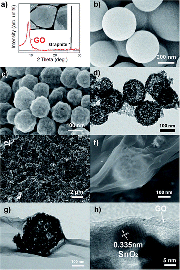
The samples in all steps of the synthesis were characterized in detail using electron microscopy and/or X-ray diffraction. Fig. 1 shows the XRD patterns of graphite and reduced graphene oxide, as well as TEM image of graphene oxide. SEM images of carbon spheres, as well as SEM images of hollow SnO2 spheres (labeled SnO2 HS) are also shown. It is obvious that the spheres are hollow and consist of very small SnO2 nanoparticles. Successful graphene wrapping is obvious from both SEM and TEM images of graphene wrapped hollow spheres, labeled SnO2 HS/GO. Additional SEM and TEM images are shown in ESI, Fig. S1 and S2.†TEM image, EDX spectrum and element mapping of SnO2 HS/GO samples after ALD alumina coating are shown in Fig. 2. It can be observed that aluminium is present in the samples, and that the element distribution is in agreement with the expectations from the sample composition.
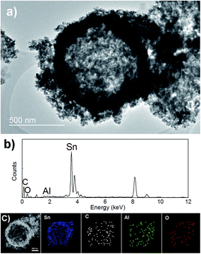 | ||
| Fig. 2 (a) TEM image of Al2O3 coated SnO2 HS/GO composite. (b and c) EDX spectrum and element mapping images of Al2O3 coated SnO2 HS/GO composite. | ||
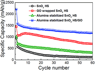
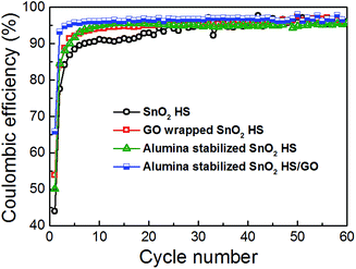
Cycling performance and coulombic efficiency of the samples are shown in Fig. 3 and 4, respectively. For SnO2 hollow spheres, initial capacity of 939 mA h g−1 drops to 571 mA h g−1 by 2nd cycle, 357 mA h g−1 by 10th cycle, and 115 mA h g−1 at 60th cycle. From the obtained results, it is obvious that simple hollow morphology is insufficient to stabilize the electrode. Initial coulombic efficiency of SnO2 HS samples of 44% increases to 95% by 24th cycle. With graphene oxide wrapping, we can observe improvements in the performance. Initial specific capacity is much higher, 1447 mA h g−1, likely due to lithium storage contribution of GO. By 2nd cycle it drops to 1059 mA h g−1, and by 20th cycle it still remains at 1143 mA h g−1 although by 60th cycle it drops to 700 mA h g−1. Initial efficiency of 54% increases to 95% by 14th cycle.
For alumina-coated SnO2 HS samples, initial capacity is similar to bare hollow spheres, 1008 mA h g−1. By second cycle it drops to 707 mA h g−1, and by 10th cycle it drops to 571 mA h g−1. After 60 cycles, the specific capacity is 309 mA h g−1, which is an obvious improvement over bare hollow spheres, but not as good as graphene wrapped hollow spheres. The initial efficiency of these samples was 50%, and it increased to 95% by 9th cycle. Finally, the samples with combined graphene wrapping and ALD coating exhibited the best performance with initial capacity of 2209 mA h g−1 (1582 mA h g−1 in the 2nd cycle) and the capacity of 1176 mA h g−1 after 60 cycles. The initial efficiency was 66%, and it rapidly increases to 96% by 5th cycle. It can be observed that the initial coulombic efficiency of SnO2 is the lowest at 44%, while with GO wrapping and ALD coating it improves to 54% and 50% respectively. Both GO wrapping and ALD coating result in 66% initial coulombic efficiency. This can likely be attributed to the improvement in the electrode stability (structural integrity)36 and the reduction of the SEI formation. It was previously reported that ALD deposition of alumina coating directly on the electrode results in a stable artificial SEI layer.34
The rate performance of different anodes is illustrated in Fig. 5. It can be observed that both SnO2 HS and SnO2 HS/GO samples exhibit inferior performance at high charge/discharge rates. For SnO2 HS we obtain 98 mA h g−1 at 1 A g−1 and 7 mA h g−1 at 2 A g−1. Graphene oxide wrapping resulted only in a small improvements at high rates with 137 mA h g−1 at 1 A g−1 and 8 mA h g−1 at 2 A g−1. On the other hand, alumina coating significantly improves the rate performance, with capacities of 417 mA h g−1 at 1 A g−1 and 211 mA h g−1 at 2 A g−1. The rate performance is further improved with the employment of both GO wrapping and ALD coating, with specific capacities of 604 mA h g−1 at 1 A g−1 and 329 mA h g−1 at 2 A g−1. It was reported that graphene wrapping of cobalt oxide hollow spheres improved both cycling and rate performance.41 However, no rate performance improvement was obtained by simple mixing, although stable cycling performance was obtained.41 It was also previously reported that ALD coating improved cycle life but reduced capacity at high rates, which was attributed to the fact that ALD layer served as a barrier to ion mobility.35 In other works however, ALD coating resulted in improvements in both cycling and rate performance.32,36,40 However, there was a difference in the effect of ALD coating in the rate performance of coated graphene and carbon nanotube samples.40 Thus, it is likely that the morphology of the material and the thickness and properties of ALD coating would affect the overall electrochemical behavior.
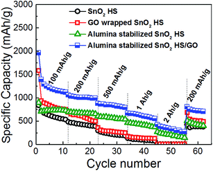 | ||
| Fig. 5 Rate performance of different electrodes at charge/discharge rates from 100 mA g−1 to 2 A g−1. | ||
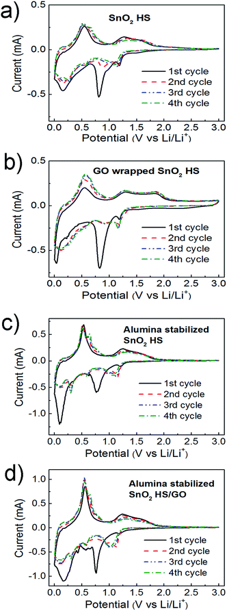
To obtain further insight into the mechanisms responsible for performance improvements for different electrode stabilization approaches, CV measurements were performed at the scan rate is 0.1 mV s−1 in the range between 5 mV to 3.0 V, as shown in Fig. 6. Electrochemical storage mechanism of SnO2 can be described as:5,6,10,22,24
| SnO2 + 4Li+ + 4e− → Sn + 2Li2O | (1) |
| Sn + xLi+ + xe− ↔ LixSn (0 ≤ x ≤ 4.4) | (2) |
In the first cathodic/anodic scans of all samples, several reduction/oxidation peaks can be resolved. The peaks in the range 0–0.6 V in the cathodic scan and the corresponding peaks in the region 0.4–0.9 V of the anodic scan can be attributed to Li–Sn alloying/dealloying processes.4–6,10,12,13,24 Low voltage feature at ∼0.01–0.1 V can also be partially due to Li intercalation into carbon.24 For all samples, we can observe a significant peak at ∼0.7–0.8 V in the first cathodic scan, which can be attributed to the irreversible reactions and the formation of the SEI layer.10,12,13 This is in agreement with the significant capacity loss in the first cycle, which is commonly attributed to irreversible reactions and SEI formation.3,4 The features at ∼0.9–1.2 V in the cathodic scan and the corresponding feature at ∼1.3 V in the anodic scan are due to partially reversible reduction of SnO2 and oxidation of Sn, respectively.4–7,13 For both GO wrapping and ALD alumina deposition, C–V curves in the second and subsequent cycles remain stable and exhibit the same shape, in agreement with literature reports on electrode stabilization by morphology optimization or ALD deposition.11,32,33
To further investigate the performance of different electrodes, we performed electron microscopy on the electrodes after cycling. Obtained SEM images are shown in Fig. 7. We can observe that a better preservation of the original morphology is obtained after graphene wrapping, which is further improved by alumina stabilization. Mitigation of the mechanical degradation of the electrode by graphene nanosheet wrapping of hollow cobalt oxide spheres was identified as a significant contributor to the stable performance of such hybrid electrodes.41 This is in agreement with the obtained results for cycling performance. It was reported that enclosing the metal oxide into an elastic and conductive carbon improves the performance by reinforcing the hollow structure and preventing aggregation.4 While ALD coating is also expected to reduce electrode pulverization due to volume changes upon lithiation/delithiaton,39 very few intact spheres can be observed in samples with ALD coating only and without graphene wrapping. However, ALD coating was reported to create adhesion to the conductive additive, which would provide performance stabilization.39 We also tried to deposit thicker alumina layers in an attempt to improve morphology stabilization by ALD coating. However, we found that significantly lower specific capacities are obtained for 3 nm (30 ALD cycles) coating of alumina compared to 1 nm (100 ALD cycles), as shown in ESI, Fig. S3.† In the case of SnO2 HS/GO samples, while comparable performance is obtained for SnO2 HS samples. This is likely due to the fact that too thick alumina layer can block lithium diffusion.30 In addition, alumina is an insulating material, and consequently there is an optimal thickness for good performance.
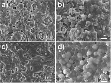 | ||
| Fig. 7 SEM images of different SnO2 HS-based electrodes after 60 cycles (a) SnO2 HS, (b) GO wrapped SnO2 HS, (c) alumina stabilized SnO2 HS, and (d) alumina stabilized GO wrapped SnO2 HS. | ||
To further investigate the effects of cycling on the morphology in alumina stabilized SnO2 HS/GO samples, TEM imaging was performed. Obtained results are shown in Fig. 8, while additional TEM images can be seen in ESI, Fig. S4.† It can be observed that SnO2 spheres after cycling no longer appear hollow. The size distribution of spheres is also changed, as illustrated in SEM images in Fig. 9. The change in the morphology from hollow porous spheres to dense spheres could possibly explain the initial irreversible capacity loss which would occur due to a significant reduction in the available surface area.
 | ||
| Fig. 8 A typical TEM image of alumina stabilized SnO2 HS/GO electrode after 60 cycles (the inset is the relevant diffraction pattern of a single SnO2 HS). | ||
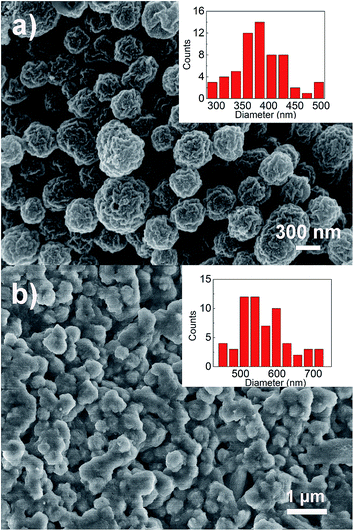 | ||
| Fig. 9 SEM images of (a) as prepared SnO2 HS (b) alumina stabilized SnO2 HS/GO electrode after 60 cycles. The inset shows the sphere diameters. | ||
Conclusions
Graphene oxide wrapping and ALD coating methods for stabilization of LIB electrodes consisting of SnO2 hollow spheres are compared. Graphene oxide wrapping provides a better buffering of volume changes and results in reduced electrode pulverization and better preservation of the original electrode morphology. On the other hand, ALD coating provides a significant improvement in the rate performance of the anodes, and it could also improve the adhesion of the metal oxide to the conductive additive since the coating is applied to entire electrode. Combination of the two stabilization techniques results in anodes with superior performance and a high degree of reversibility of the electrochemical reactions.Acknowledgements
Financial support from the Strategic Research Theme on Clean Energy and Seed Funding for Basic Research Grant of the University of Hong Kong and National Science Fund of China (NSFC no. 21403103) is acknowledged. The authors would like to thank Prof. K. Y. Chan for the use of the electrochemical workstation.Notes and references
- Z. Y. Wang, L. Zhou and X. W. Lou, Adv. Mater., 2012, 24, 1903 CrossRef CAS PubMed
.
- F. Bonaccorso, L. Colombo, G. H. Yu, M. Stoller, V. Tozzini, A. C. Ferrari, R. S. Ruoff and V. Pellegrini, Science, 2015, 347, 1246501 CrossRef PubMed
.
- V. Etacheri, G. A. Serisenbaeva, J. Caruthers, G. Daniel, J. M. Nedelec, V. G. Kessler and V. G. Pol, Adv. Energy Mater., 2015, 5, 1401289 Search PubMed
.
- L. Zhang, H. B. Wu, B. Liu and X. W. Lou, Energy Environ. Sci., 2014, 7, 1013 Search PubMed
.
- A. Bhaskar, M. Deepa and T. N. Rao, Nanoscale, 2014, 6, 10762 RSC
.
- P. Gurunathan, P. M. Ette and K. Ramesha, ACS Appl. Mater. Interfaces, 2014, 6, 16556 CAS
.
- J. Liang, X. Y. Yu, H. Zhou, H. B. Wu, S. J. Ding and X. W. Lou, Angew. Chem., Int. Ed., 2014, 53, 12803 CrossRef CAS PubMed
.
- Z. Q. Zhu, S. W. Wang, J. Du, Q. Jin, T. R. Zhang, F. Y. Cheng and J. Chen, Nano Lett., 2014, 14, 153 CrossRef CAS PubMed
.
- S. J. Han, B. Jang, T. Kim, S. M. Oh and T. Hyeon, Adv. Funct. Mater., 2005, 15, 1845 CrossRef CAS
.
- Y. F. Dong, Z. B. Zhao, Z. Y. Wang, Y. Liu, X. Z. Wang and J. S. Qiu, ACS Appl. Mater. Interfaces, 2015, 7, 2444 CAS
.
- Q. H. Tian, Z. X. Zhang, L. Yang and S. I. Hirano, J. Power Sources, 2015, 279, 528 CrossRef CAS
.
- Q. H. Tian, Y. Tian, Z. X. Zhang, L. Yang and S. Hirano, J. Power Sources, 2015, 280, 397 CrossRef CAS
.
- Y. Li, Q. Meng, J. Ma, C. L. Zhu, J. R. Cui, Z. X. Chen, Z. P. Guo, T. Zhang, S. M. Zhu and D. Zhang, ACS Appl. Mater. Interfaces, 2015, 7, 11146 CAS
.
- C. Guan, X. H. Wang, Q. Zhang, Z. X. Fan, H. Zhang and H. J. Fan, Nano Lett., 2014, 14, 4852 CrossRef CAS PubMed
.
- P. Wu, H. Wang, Y. W. Tang, Y. M. Zhou and T. H. Lu, ACS Appl. Mater. Interfaces, 2014, 6, 3546 CAS
.
- J. Yue, X. Gu, L. Chen, N. Wang, X. L. Jiang, H. Y. Xu, J. Yang and Y. T. Qian, J. Mater. Chem. A, 2014, 2, 17421 CAS
.
- D. H. Wei, J. w. Liang, Y. C. Zhu, Z. Q. Yuan, N. Li and Y. T. Qian, Part. Part. Syst. Charact., 2013, 30, 143 CrossRef CAS
.
- J. S. Lee, K. H. You and C. B. Park, Adv. Mater., 2012, 24, 1084 CrossRef CAS PubMed
.
- S. B. Yang, X. L. Feng, S. Ivanovici and K. Müllen, Angew. Chem., Int. Ed., 2010, 49, 8408 CrossRef CAS PubMed
.
- Y. T. Xu, Y. Guo, C. Li, X. Y. Zhou, M. C. Tucker, X. Z. Fu, R. Sun and C. P. Wong, Nano Energy, 2015, 11, 38 CrossRef CAS
.
- M. Shahid, N. Yesibolati, M. C. Reuter, F. M. Ross and H. N. Alshareef, J. Power Sources, 2014, 263, 239 CrossRef CAS
.
- H. Yang, Z. H. Hou, N. B. Zhou, B. H. He, J. G. Cao and Y. F. Kuang, Ceram. Int., 2014, 40, 13903 CrossRef CAS
.
- J. Zhu, G. H. Zhang, X. Z. Yu, Q. H. Li, B. G. Lu and Z. Xu, Nano Energy, 2014, 3, 80 CrossRef CAS
.
- X. Liu, F. Z. Liu, Q. Sun, A. M. C. Ng, A. B. Djurišić, M. H. Xie, C. Z. Liao and K. M. Shih, ACS Appl. Mater. Interfaces, 2014, 6, 13478 CAS
.
- A. K. Geim, Science, 2009, 324, 1530 CrossRef CAS PubMed
.
- R. J. Chen, T. Zhao, T. Tian, S. Cao, P. R. Coxon, K. Xi, D. Fairen-Jimenez, R. V. Kumar and A. K. Cheetham, APL Mater., 2014, 2, 124109 CrossRef
.
- J. Hassoun, F. Bonaccoro, M. Agostini, M. Angelucci, M. G. Betti, R. Cingolani, M. Gemmi, C. Mariani, S. Panero, V. Pellegrini and B. Scrosati, Nano Lett., 2014, 14, 4901 CrossRef CAS PubMed
.
- E. Quesnel, F. Roux, F. Emieux, P. Faucherand, E. Kymaki, G. Volonakis, F. Giustino, B. Martin-Garcia, I. Moreels and S. A. Gursel, et al., 2D Mater., 2015, 2, 030204 CrossRef
.
- J. Liu and X. L. Sun, Nanotechnology, 2015, 26, 024001 CrossRef CAS PubMed
.
- Y. He, X. Q. Yu, Y. H. Wang, H. Li and X. J. Huang, Adv. Mater., 2011, 23, 4938 CrossRef CAS PubMed
.
- M. P. Yu, A. J. Wang, Y. S. Wang, C. Li and G. Q. Shi, Nanoscale, 2014, 6, 11419 RSC
.
- N. Yesibolati, M. Shahid, W. Chen, M. N. Hedhili, M. C. Reuter, F. M. Ross and H. N. Alshareef, Small, 2014, 10, 2849 CrossRef CAS PubMed
.
- D. N. Wang, J. L. Yang, J. Liu, X. F. Li, R. Y. Li, M. Cai, T. K. Sham and X. L. Sun, J. Mater. Chem. A, 2014, 2, 2306 CAS
.
- Y. S. Jung, A. S. Cavanagh, L. A. Riley, S. H. Kang, A. C. Dillon, M. D. Groner, S. M. George and S. H. Lee, Adv. Mater., 2010, 22, 2172 CrossRef CAS PubMed
.
- L. A. Riley, S. K. Atta, A. S. Cavanagh, Y. F. Yan, S. M. George, P. Liu, A. C. Dillon and S. H. Lee, J. Power Sources, 2011, 196, 3317 CrossRef CAS
.
- T. Hu, M. Xie, J. Zhong, H. T. Sun, X. Sun, S. Scott, S. M. George, C. S. Liu and J. Lian, Carbon, 2014, 76, 141 CrossRef CAS
.
- C. M. Ban, M. Xie, X. Sun, J. J. Travis, G. Wang, H. T. Sun, A. C. Dillon, J. Lian and S. M. George, Nanotechnology, 2013, 24, 424002 CrossRef PubMed
.
- Y. S. Jung, P. Lu, A. S. Cavanagh, C. M. Ban, G. H. Kim, S. H. Lee, S. M. George, S. J. Harris and A. C. Dillon, Adv. Energy Mater., 2013, 3, 213 CrossRef CAS
.
- L. A. Riley, A. S. Cavanagh, S. M. George, Y. S. Jung, Y. F. Yan, S. H. Lee and A. C. Dillon, ChemPhysChem, 2010, 11, 2124 CrossRef CAS PubMed
.
- X. Sun, M. Xie, J. J. Travis, G. K. Wang, H. T. Sun, J. Lian and S. M. George, J. Phys. Chem. C, 2013, 117, 22497 CAS
.
- H. T. Sun, X. Sun, T. Hu, M. P. Yu, F. Y. Lu and J. Lian, J. Phys. Chem. C, 2014, 118, 2263 CAS
.
Footnote |
| † Electronic supplementary information (ESI) available: TEM and SEM images, comparison of cycling performance with 1 nm and 3 nm ALD alumina coating. See DOI: 10.1039/c5ra22482a |
| This journal is © The Royal Society of Chemistry 2015 |

