Effect of molybdenum carbide concentration on the Ni/ZrO2 catalysts for steam-CO2 bi-reforming of methane†
Weizuo Li,
Zhongkui Zhao*,
Panpan Ren and
Guiru Wang
State Key Laboratory of Fine Chemicals, Department of Catalysis Chemistry and Engineering, School of Chemical Engineering, Dalian University of Technology, Dalian 116024, P.R. China. E-mail: zkzhao@dlut.edu.cn; Fax: +86-411-84986354
First published on 11th November 2015
Abstract
The effect of the molybdenum carbide concentration, in the range of 0.2–3.0 wt% (nominal loading), on modified supported nickel catalysts on ZrO2 (Mo2C–Ni/ZrO2) for steam-CO2 bi-reforming of methane was investigated by correlating the various characterization results, including X-ray photoelectron spectroscopy (XPS), X-ray diffraction (XRD), transmission electron microscopy (TEM), N2 physisorption (BET), H2 temperature-programmed reduction (H2-TPR), inductively coupled plasma atomic emission spectroscopy (ICP-AES) and thermogravimetric analysis (TGA), to the catalytic performance. It was found that the Ni dispersion increased with an increase in Mo2C loading, which might lead to the strong Ni–ZrO2 interactions confirmed by XPS. However, an appropriate Mo2C loading is required to obtain a high surface Mo(II) content that may promote the reforming reaction by serving as another active species besides Ni. The optimized modified Ni/ZrO2 with 0.5 wt% nominal Mo2C loading exhibits higher catalytic activity than the others for steam-CO2 bi-reforming of methane, which is ascribed to an increased Ni dispersion and a higher Mo(II) content. Moreover, the developed 0.5 wt% Mo2C–10 wt% Ni/ZrO2 catalyst shows higher catalytic stability in comparison with the unmodified 10 wt% Ni/ZrO2 catalyst, which is ascribed to the different coke types caused by the diverse strength of the Ni–ZrO2 interactions for the modified and unmodified catalysts.
1. Introduction
Methane is one of the most significant C1 resources from natural gas hydrates, natural gas, coalbed gas, shale gas, methane hydrates, livestock excretion, fermented wastes, and other sources, but it is also an important greenhouse gas besides CO2. Therefore, much attention has been focused on CO2 reforming of methane for synthesis gas production owing to both resource utilization and environmental issues. In particular, due to depleted crude oil resources, the gas to liquid (GTL) process has been considered as an alternative technology to produce clean synthesized fuel and other chemicals from methane via the Fischer–Tropsch synthesis in large-scale production.1–8 For the GTL process, it’s highly desirable to develop an economic and efficient method for synthesis gas production since it accounts for about 60% of the total capital cost. Moreover, it is required to produce synthesis gas with variable H2/CO ratios according to the target process, such as Fischer–Tropsch or methanol synthesis.9–11The commonly used methane transformation technologies for synthesis gas production, steam reforming, dry reforming, or partial oxidation, produce a synthesis gas mixture composed of a H2/CO ratio close to 3, 1 or 2, respectively. Additional steps are required to adjust the H2/CO ratio to satisfy the specific requirement for the downstream transformation of the synthesis gas. Therefore, it’s highly desirable to develop an efficient synthesis gas production method to overcome the drawbacks of the conventional reforming processes. Recently, combined reforming technologies including bi and tri-reforming of methane have attracted extensive interest owing to the elimination of the additional process of adjusting the H2/CO ratio.12,13 Partial oxidation of methane is an energy-saving exothermic reaction and it has attracted much attention.14–20 However, many issues such as difficult to control, easily-produced hot spots and the associated dangers of explosion limit the large-scale application of combined reforming processes involving partial oxidation reforming. Steam-CO2 bi-reforming of methane has been considered as a judicious approach for potential industrial application in synthesis gas production as the H2/CO ratio can be easily adjusted by controlling the H2O/CO2 ratio in the feed and the catalyst has an improved coke-resistance due to the introduction of steam.2–9,21–23 Thus it is essential to develop a robust mixed reforming catalyst with high catalytic activity and good coke resistance. In the bi-reforming process, Ni-based catalysts have been extensively employed as promising catalysts owing to their low cost but high activity, comparable to noble metal catalysts for reforming of methane.2,3,8,24–27
However, Ni-based catalysts are faced with some barriers, including quick deactivation owing to metal sintering and coke deposition in the severe reforming operating conditions. Therefore, many efforts have been focused on ways to inhibit the metal sintering and coke deposition. Some interesting and efficient approaches such as employing diverse preparation methods, steam treatment, changing the support type and introducing additives have been performed to improve the catalytic stability by minimizing coke formation and inhibiting the thermal sintering of the Ni metal.2,8,28,29 In particular, recent studies demonstrated that the catalytic activity and stability of Ni-based catalysts can be significantly improved through the introduction of a small amount of noble metals, such as Rh and Pt, resulting from the improved dispersion and reducibility of NiO, enhanced sintering-resistance, and suppressed coke deposition.21,25–29 The noble metal modification of Ni-based catalysts could be considered as a fascinating approach to improve the catalytic performance, especially the stability, of Ni-based reforming catalysts. However, this approach is limited in its large scale application owing to the high cost and the poor availability of noble metals. There is an urgent need to develop efficient but low cost alternatives to noble metals for improving the catalytic stability of Ni-based catalysts in the reforming process.
Fortunately, non-precious transition-metal carbides, such molybdenum carbide, as Pt-like metals, have attracted much attention as promising materials due to their outstanding bulk and surface physicochemical properties.25,26 In previous reports, metal carbides, as alternatives to noble metals, have been demonstrated as efficient catalysts and have been widely used in many reactions such as the decomposition of hydrazine, ammonia and methanol, Fischer–Tropsch synthesis, hydrogenolysis, water–gas shift, reduction of nitroarenes, electrocatalysis and reforming of diverse substrates.30,31 According to the literature, we found that the studies focused on the use of carbides as the main active component, and the added Ni just acts as a promoter to modify the catalyst structure and catalytic performance, or the use of small amounts of metal oxide to modify the Ni-based catalyst and decrease the rate of coking in dry or steam methane reforming.32–37 However, there is no report on the use of small amounts of metal carbide in Ni-based catalysts to improve their stability in steam-CO2 bi-reforming of methane. Based on the excellent thermal and chemical stability, high oxygen mobilization, basicity and redox properties, ZrO2 has been extensively used as a promising support for reforming catalysts.18
Herein, we first report the molybdenum carbide modified Ni/ZrO2 catalyst for steam-CO2 bi-reforming of methane (SCRM). Through adding the appropriate amount of molybdenum carbide to the supported Ni catalyst, the catalytic activity and stability of Ni-based catalysts can be significantly improved. Various characterization techniques such as XRD, TEM, BET, ICP-AES, and TGA were employed to investigate the effect of the Mo2C concentration on the Ni/ZrO2 catalysts for synthesis gas production. Results show that the developed molybdenum carbide modified supported nickel catalyst, prepared by the urea-assisted hydrothermal process, incipient wetness impregnation, and subsequent reduction carburization approach in this work, shows much superior catalytic stability for steam-CO2 bi-reforming of methane, which makes it a promising candidate for syngas production via steam-CO2 bi-reforming of methane, a key process in the gas to liquid process. Moreover, it was also found that the addition of a small amount of Mo2C into the supported Ni catalyst significantly improved the catalytic stability, which may be ascribed to the improved NiO dispersion and suppression of carbon shell formation resulting from the strong Ni–Mo2C interactions.
2. Experimental
2.1. Catalyst preparation
The ZrO2 support was synthesized using a modified hydrothermal method.38 In a typical synthesis, 13.7 g of Zr(NO3)4·5H2O (Sinopharm Chemical Reagent Co., Ltd) and 19.2 g of urea were dissolved in deionized water. The solution was vigorously stirred for 1 h at room temperature, and was then transferred into a Teflon-lined stainless-steel autoclave, maintained at 180 °C for 20 h, and subsequently cooled to room temperature. The resulting precipitate was collected and then washed with deionized water until the filtrate became neutral. Then, the sample was dried at 105 °C for 12 h, following calcination at 400 °C for 4 h, and then the ZrO2 support was obtained. The as-synthesized ZrO2 support with a 141.2 m2 g−1 BET surface area was obtained.The series of modified 10 wt% Ni/ZrO2 catalysts with diverse Mo2C loadings from 0.2 to 3 wt% (nominal content, calculated on the amount of Mo2C added) were prepared by the incipient wetness impregnation and subsequent reduction carburization method (IWI–RC). For comparison, the unmodified Ni/ZrO2 catalyst was prepared by the same procedure but in the absence of ammonia heptamolybdate ((NH4)6Mo7O24·4H2O) in the IWI process. Generally, the aqueous solution of nickel nitrate (Ni(NO3)2·6H2O) and (NH4)6Mo7O24·4H2O were impregnated onto the ZrO2 support. The obtained sample was dried at 105 °C for 12 h and subsequently calcined at 550 °C for 6 h in a muffle furnace to prepare NiO–MoOx/ZrO2. The resultant NiO–MoOx/ZrO2 was subjected to the reduction carburization process in CH4–H2 (20 vol% CH4) with the heating process as follows: from room temperature to 300 °C at a ramp rate of 5 °C min−1, then from 300 °C to 850 °C at a ramp rate of 2 °C min−1, and maintaining this temperature for 30 min. The resulting Mo2C–Ni/ZrO2 samples were passivated in a mixture of 1% O2/Ar for 12 h, and the series of Mo2C modified Ni/ZrO2 catalysts was obtained. As is seen from Table 1, a smaller specific surface area of the Mo2C modified Ni/ZrO2 in comparison to the unmodified catalyst can be observed, although the unmodified sample was also subjected to the RC process. The increase in the nominal Mo2C loading doesn’t lead to a visible change in the surface area.
| x (%) | SBETa (m2 g−1) | CSNib | WCCPc | NXPSd | |||
|---|---|---|---|---|---|---|---|
| Fresh | Spent | Ni (wt%) | Mo (wt%) | Ni/Zr | Mo/Zr | ||
| a BET specific surface area from N2 physisorption.b The average crystallite sizes of Ni estimated from the Scherrer equation according to the Ni (111) plane.c Weight content from ICP-AES measurements.d Surface atomic ratio from XPS analysis. | |||||||
| 0 | 57 | 16.8 | 24.3 | 7.53 | — | 0.21 | — |
| 0.2 | 37 | 16.5 | — | 7.51 | 0.14 | 0.23 | 0.0025 |
| 0.5 | 39 | 14.8 | 22.1 | 7.49 | 0.33 | 0.22 | 0.0067 |
| 1.0 | 38 | 14.4 | — | 7.50 | 0.71 | 0.22 | 0.0124 |
| 2.0 | 38 | 13.5 | — | 7.52 | 1.44 | 0.23 | 0.0263 |
| 3.0 | 39 | 13.3 | — | 7.51 | 2.11 | 0.22 | 0.0396 |
2.2. Catalyst characterization
The XRD patterns were collected from 10 to 80° at a step width of 0.02° using a Rigaku Automatic X-ray Diffractometer (D/Max 2400) equipped with a Cu Kα source (λ = 1.5406 Å). The average crystallite sizes were estimated on the basis of the Scherrer formula over the multiple characteristic diffraction peaks by the MDI Jade 5 software. The XPS experiments were carried out on an ESCALAB 250 XPS system with a monochromatized Al Kα X-ray source (15 kV, 150 W, 500 μm, pass energy = 50 eV). The binding energy was calibrated according to the C 1s photoelectron peak at 284.6 eV, and the binding energy of Mo 3d was analyzed at 220–240 eV using the Shirley baseline-correction method. HRTEM images were obtained using a Tecnai F30 HRTEM instrument (FEI Corp.) at an acceleration voltage of 300 kV. The impregnation of the catalyst was investigated by measuring the Ni and Mo contents (Table 2) using the ICP-AES technique on the ICP spectrometer (Optima 2000DV, Perkin Elmer). H2-TPR experiments were performed in an in-house constructed system equipped with a TCD (thermal conductivity detector) to measure H2 consumption. A quartz tube was loaded with 50 mg of catalyst pretreated by calcination in Ar at 300 °C for 30 min and was then cooled down to ambient temperature in Ar. After that, it was reduced with a 10 vol% H2–Ar mixture (30 ml min−1) by heating up to 850 °C at a ramp rate of 10 °C min−1. TGA analysis was conducted to study the amount of coke deposited on the spent LA-Ni/ZrO2 and Ni/ZrO2 catalysts using a Perkin-Elmer STA 6000 instrument at a heating rate of 10 °C min−1 from 30 to 800 °C in an air stream.| x (%) | Mo(II)a (%) | Mo(IV)a (%) | Mo(V)a (%) | Mo(VI)a (%) | NMo(II)/Zrb | Zr(IV)c (%) | Zr(III)c (%) | NNi(0)/Nid (%) |
|---|---|---|---|---|---|---|---|---|
| a Percentage of diverse Mo species in the total Mo content.b The atomic ratio of Mo(II) to total Zr from XPS, calculated by the Mo(II) percentage in the total Mo content multiplied by the atomic ratio of surface Mo to Zr calculated from XPS.c Percentage of diverse Zr species in the total Zr content.d The atomic ratio of Ni(0) to total Ni calculated from XPS. | ||||||||
| 0 | — | — | — | — | — | 65.7 | 34.3 | 51.7 |
| 0.2 | 100 | — | — | — | 0.0025 | 62.7 | 37.3 | 49.9 |
| 0.5 | 85.2 | — | — | 14.8 | 0.0057 | 56.4 | 43.6 | 41.0 |
| 1.0 | 41.6 | — | 12.5 | 45.9 | 0.0054 | 53.4 | 46.6 | 34.9 |
| 2.0 | 19.4 | 25.3 | 11.8 | 43.5 | 0.0051 | 50.0 | 50.0 | 31.9 |
| 3.0 | 12.3 | 25.0 | 6.8 | 55.5 | 0.0049 | 48.0 | 52.0 | 29.9 |
2.3. Catalytic performance measurement
The catalytic performance measurements were performed in a quartz tube fixed-bed continuous reactor (6 mm O.D.) at atmospheric pressure. In each test, 50 mg catalyst with a 60–80 mesh particle size was loaded between two quartz wool plugs. The temperatures were measured using K-type thermocouples and controlled by a PID controller (Xiamen Yudian). Before the reaction, the catalyst was reduced at 700 °C for 2 h under a mixture of 20% H2 in N2 at a flow rate of 30 ml min−1. The reaction feed was controlled by the mass flow controllers (Huibolong Co.). The reactions over the diverse modified Ni/ZrO2 catalysts were performed at 700 °C, and the feed (1.0![[thin space (1/6-em)]](https://www.rsc.org/images/entities/char_2009.gif) :
:![[thin space (1/6-em)]](https://www.rsc.org/images/entities/char_2009.gif) 0.4
0.4![[thin space (1/6-em)]](https://www.rsc.org/images/entities/char_2009.gif) :
:![[thin space (1/6-em)]](https://www.rsc.org/images/entities/char_2009.gif) 0.8
0.8![[thin space (1/6-em)]](https://www.rsc.org/images/entities/char_2009.gif) :
:![[thin space (1/6-em)]](https://www.rsc.org/images/entities/char_2009.gif) 1.0 of CH4/CO2/H2O/N2) was introduced into the reactor at 36
1.0 of CH4/CO2/H2O/N2) was introduced into the reactor at 36![[thin space (1/6-em)]](https://www.rsc.org/images/entities/char_2009.gif) 000 ml h−1 g−1 gas hourly space velocity (GHSV). N2 was used as an internal standard to calculate the CH4 and CO2 conversion. The effluent gas was passed through a trap to condense the residual steam and then analyzed using a gas chromatograph on-line with a molecular sieve column and a Porapaq Q column. The data were taken at 30 min for the initial performance measurement. For the stability test, the reaction conditions are as follows: 50 mg catalyst, 1.0
000 ml h−1 g−1 gas hourly space velocity (GHSV). N2 was used as an internal standard to calculate the CH4 and CO2 conversion. The effluent gas was passed through a trap to condense the residual steam and then analyzed using a gas chromatograph on-line with a molecular sieve column and a Porapaq Q column. The data were taken at 30 min for the initial performance measurement. For the stability test, the reaction conditions are as follows: 50 mg catalyst, 1.0![[thin space (1/6-em)]](https://www.rsc.org/images/entities/char_2009.gif) :
:![[thin space (1/6-em)]](https://www.rsc.org/images/entities/char_2009.gif) 0.4
0.4![[thin space (1/6-em)]](https://www.rsc.org/images/entities/char_2009.gif) :
:![[thin space (1/6-em)]](https://www.rsc.org/images/entities/char_2009.gif) 0.8
0.8![[thin space (1/6-em)]](https://www.rsc.org/images/entities/char_2009.gif) :
:![[thin space (1/6-em)]](https://www.rsc.org/images/entities/char_2009.gif) 1.6 of CH4/CO2/H2O/N2 and 60
1.6 of CH4/CO2/H2O/N2 and 60![[thin space (1/6-em)]](https://www.rsc.org/images/entities/char_2009.gif) 000 ml h−1 g−1 GHSV at 850 °C.
000 ml h−1 g−1 GHSV at 850 °C.
The CH4 conversion, CO2 conversion, and H2/CO molar ratio were calculated on the basis of the following equations:
CH4 conversion
CO2 conversion
H2/CO molar ratio
3. Results and discussion
3.1. Characterization of catalysts
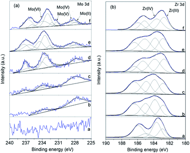
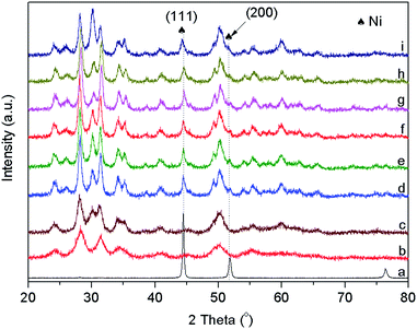
The surface components and chemical state of the Mo2C modified and unmodified Ni/ZrO2 were measured by XPS analysis. The XPS spectra are presented in Fig. 1 and S1,† and the quantitative analytical results are shown in Tables 1 and 2. From Table 1, a diverse loading of Mo was successfully introduced into the modified catalysts. From ref. 39–45 the Mo 3d region was deconvoluted to analyze the distribution of the molybdenum oxide states, and the peaks at approximately 228.2, 229.0, 231.4, and 234.0 eV can be assigned to Mo(II), Mo(IV), Mo(V), and Mo(VI) of the Mo 3d5/2 region. No XPS peak corresponding to metallic Mo appearing at about 227.0 eV (Mo 3d5/2) can be detected for any samples. From Table 2, the molar ratio of Mo(II) to Zr (NMo(II)/Zr, denoted as surface Mo(II) content) increases as the nominal Mo loading rises, and reaches a maximum for the 0.5 wt% Mo2C–Ni/ZrO2 sample, but it decreases as the nominal Mo loading is further increased from 0.5 to 3.0 wt%. Mo(II) corresponds to Mo2C,46 which could be an active species for reforming of methane. The Zr 3d was fitted into four peaks at approximately 182.7, 183.8, 185.1, and 186.4 eV. The former two peaks can be assigned to Zr(III) and Zr(IV) of Zr 3d5/2 (the latter two are in the Zr 3d3/2 region). From Table 2, the Zr(III) percentage in the total Zr containing Zr(III) and Zr(IV) monotonously increases with the increase in the introduced Mo2C, and as a corresponding result, the molar ratio of Ni(0) to total Ni decreases. The formation of Zr(III) could result from two possible processes: one is the reduction of Zr(IV) under the reduction atmosphere in the RC process for the preparation of Mo2C–Ni/ZrO2; the other is the solid state reaction of Ni and ZrO2 in the RC process.47 From Fig. S2,† the ZrO2 was hardly reduced by hydrogen even when the temperature was increased up to 850 °C. That is to say, only a very small amount of Zr(IV) can be reduced to Zr(III) in the above mentioned RC process and the large amount of Zr(III) on the Mo2C modified Ni/ZrO2 catalysts confirmed by the XPS analysis (Table 2) must result from the solid state reaction of the reduced Ni and Zr(IV). The continuous increase in Zr(III) content with the increase in Mo content suggests that the introduced Mo can enhance this solid state reaction, which might be ascribed to the intensified Ni–ZrO2 interaction. Furthermore, from Table 2, the amount of surface Mo(II), denoted as Mo2C, reaches a maximum on 0.5 wt% Mo2C–Ni/ZrO2, and then decreases as the Mo content is further increased. However, the percentage of Zr(III) continuously increases with the increase of Mo content, suggesting that all Mo species can enhance the solid state reaction between Ni and Zr(IV), and not just Mo2C. The above analysis presents evidence that the introduction of Mo can facilitate the Ni–ZrO2 interaction. Then why does the Mo introduction lead to stronger Ni–ZrO2 interactions? The XRD results provide one of the reasons.From Fig. 2, the metallic Ni phase is identified (JCPDS no. 03-1051), and the average crystalline size of Ni was estimated by the Scherrer equation (Table 1). However, no XRD peak corresponding to the Mo2C phase can be found, which is ascribed to the very low content of Mo2C in the catalysts (generally it is invisible when the content is not more than 4%) or the possible insertion of Mo2C into Ni or ZrO2. From Table 1, the average crystalline size decreases from 16.8 to 13.3 nm as the nominal Mo2C content is increased from 0 to 3.0 wt%. The decrease in Ni crystalline size may strengthen the interactions of Ni with the ZrO2 support, which is consistent with the results from XPS analysis.
3.2. Catalytic activity for steam-CO2 reforming of methane
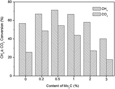
Fig. 3 displays the catalytic activity of the Mo2C modified and unmodified Ni/ZrO2 for the SCRM reaction. The catalytic activity increases as the nominal Mo2C loading is increased, and reaches the maximum conversion for both CH4 and CO2 when 0.5 wt% Mo2C is used. However, a further increase in Mo2C leads to a decreased catalytic activity. Correlating the reaction results to the catalyst’s nature, the promoting effect of the addition of an appropriate amount of Mo2C onto the catalytic performance of the supported Ni catalysts is independent of the surface area since the change in Mo loading doesn’t vary the surface area. Moreover, it was found that Mo(II) can efficiently enhance the SCRM reaction. For one thing, the decrease in Ni crystalline size with the increase in Mo loading, confirmed by XRD (Table 1), favors the reaction. However, many inactive MoOx species may cover the active sites.46,48 In addition, Mo(II) (Mo2C) may also provide active sites for the reforming reaction as Mo2C has Pt-like electronic properties and Pt is active for reforming. As a consequence, 0.5 wt% nominal Mo2C loading is required for higher catalytic activity.3.3. Stability for steam-CO2 reforming of methane
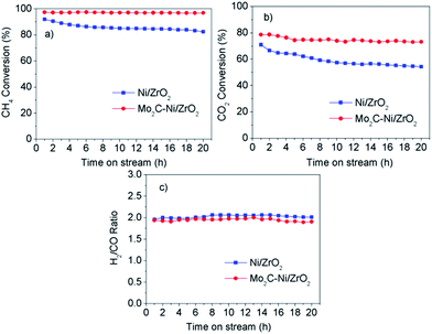
The development of stable SCRM catalysts is a major concern for their industrial application. Herein, the effect of Mo2C addition on the catalytic stability of the Ni/ZrO2 catalysts for the SCRM reaction was investigated, and the results are displayed in Fig. 4. The optimized catalyst (0.5 wt% Mo2C–10 wt% Ni/ZrO2) exhibits higher catalytic stability than the unmodified Ni/ZrO2, and no obvious decrease in the CH4 and CO2 conversions can be observed as the time on stream is extended to 20 h. This makes it a potential candidate for use in synthesis gas production via the SCRM reaction.Generally, the sintering of metallic particles and carbon deposition on the catalysts are responsible for catalyst deactivation in methane reforming.24 XRD, TEM, and TGA were thus employed to reveal the reason why the addition of Mo2C can improve the catalyst’s stability for the SCRM reaction.
Fig. 5 presents the XRD patterns of the fresh and spent supported Ni catalysts on ZrO2 with and without Mo2C modification, and the average crystalline size of Ni was estimated on the basis of the Ni (111) plane by the Scherrer equation (Table 1). From Fig. 5 and Table 1, the sintering phenomenon exists on both the modified and unmodified Ni/ZrO2 after they are subjected to the high temperature SCRM reaction process, and the addition of Mo2C doesn’t cause a visible sintering-resistance. This is different from the effect of adding precious metals that can inhibit Ni sintering,21 although Mo2C is a precious metal-like material. Thus the superior stability may result from the unique coke behaviour. Fig. 6 presents the TGA/DSC profiles of the two spent catalysts. From Fig. 6, the amount of coke deposition on the modified catalyst is not less than that on the unmodified one, and therefore the higher stability of the modified Ni/ZrO2 catalyst may result from the coke properties. Furthermore, from the DTG curves, the coke on both of the spent samples is of two chemical structures: one is amorphous carbon (α-carbon, at around 300 °C) and the other is graphitized (γ-carbon, at around 600 °C), which is consistent with the reported results.49 It’s worth mentioning that the peak corresponding to γ-carbon over the modified catalyst shifts to a lower temperature in comparison with that over the unmodified one, suggesting a lower degree of graphitization. This confirms that the coke on the two spent catalysts is of different chemical structures, which may be responsible for the different catalytic stability. Although the amount of coke on the developed catalyst is not less than on the unmodified one, the modified catalyst shows superior catalytic stability as shown in Fig. 4.
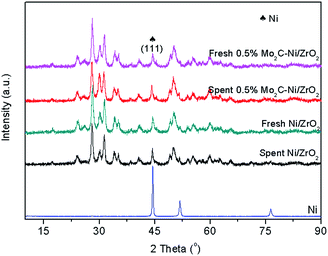 | ||
| Fig. 5 XRD patterns of fresh and spent supported Ni catalysts on ZrO2 with and without Mo2C modification. | ||
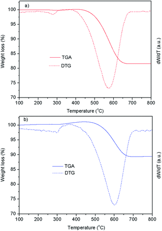 | ||
| Fig. 6 TGA/DTG profiles of spent supported Ni catalysts on ZrO2 with (a) and without (b) Mo2C modification. | ||
The difference in the coke deposited on the two spent catalysts was further confirmed by TEM analysis. Fig. 7 presents the TEM images of the spent Ni/ZrO2 catalysts with and without modification. From Fig. 6, the coke deposited on the spent Mo2C–Ni/ZrO2 catalyst is completely different from that on the unmodified one. It can be observed that two kinds of carbon are deposited: whisker-like carbon on the modified catalyst and shell-like coke encapsulating the Ni particles. It was previously reported50 that the different strengths of Ni-support interactions can lead to different coke morphologies, and a weak Ni-support interaction can result in shell-like coke encapsulating Ni, owing to the Ni being lifted up by the coke species. However, for the supported Ni catalysts with strong metal–support interactions, the Ni cannot detach from the support, which results in whisker-like coke formation. In this work, whisker-like coke is deposited on the Mo2C modified Ni/ZrO2 catalyst while shell-like coke is observed on the unmodified catalyst, which is ascribed to the different strength of the Ni–ZrO2 interactions as confirmed by the above XPS analysis.
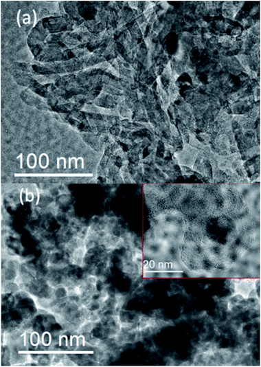 | ||
| Fig. 7 TEM images of coke on the spent Mo2C–Ni/ZrO2 (a) and Ni/ZrO2 (b) catalysts. Inset in Fig. 7b is magnified shell-like carbon. | ||
Scheme 1 illustrates the proposed mechanism for the effect of the coke morphology on the SCRM reaction. For the whisker-like coke on the modified Ni/ZrO2 catalyst, the Ni active sites are still accessible to the reaction mixture (Scheme 1). However, the shell-like coke encapsulating the Ni active sites of the unmodified Ni/ZrO2 catalyst would hinder the access of the reaction feed to the active sites. As a consequence, the modified Ni/ZrO2 catalyst exhibited much higher catalytic stability for the SCRM reaction in comparison to the unmodified catalyst.
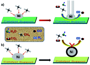 | ||
| Scheme 1 Schematic illustration for steam-CO2 bi-reforming over Mo2C modified (a) and unmodified (b) supported Ni catalysts on ZrO2. | ||
4. Conclusions
In summary, the effect of the addition of low-content Mo2C on the catalyst nature and catalytic performance in SCRM was investigated. The Mo2C modified Ni/ZrO2 exhibits superior catalytic activity and stability for the SCRM reaction compared to the unmodified one, which is ascribed to the catalysis of Mo2C, improved Ni dispersion and the different coke morphologies caused by the change in the Ni–ZrO2 interactions. An appropriate Mo2C loading is required. Moreover, it was found that the promoting effect of the addition of an appropriate amount of Mo2C on the catalytic performance of the supported Ni catalysts is independent of the surface area since the change in Mo loading doesn’t vary the surface area. The improving effect of adding Mo2C to the SCRM catalyst, with low cost in comparison with precious metals, makes it a promising approach for preparing excellent SCRM catalysts with industrial prospects.Acknowledgements
This work is financially supported by the Joint Fund of Coal, set up by National Natural Science Foundation of China and Shenhua Co., Ltd. (grant no. U1261104), and the National Natural Science Foundation of China (grant no. 21276041), and also sponsored by the Chinese Ministry of Education via the Program for New Century Excellent Talents in University (grant no. NCET-12-0079), the Natural Science Foundation of Liaoning Province (grant no. 2015020200) and the Fundamental Research Funds for the Central Universities (grant no. DUT15LK41).Notes and references
- A. T. Ashcroft, A. K. Cheetham, M. L. H. Green and P. D. F. Vernon, Nature, 1991, 352, 225–226 CrossRef CAS
.
- I. H. Son, S. J. Lee, A. Soon, H.-S. Roh and H. Lee, Appl. Catal., B, 2013, 134–135, 103–109 CrossRef CAS
.
- H.-S. Roh, K. Y. Koo, U. D. Joshi and W. L. Yoon, Catal. Lett., 2008, 125, 283–288 CrossRef CAS
.
- X. Du, D. Zhang, R. Gao, L. Huang, L. Shi and J. Zhang, Chem. Commun., 2013, 49, 6770–6772 RSC
.
- Q. H. Zhang, Y. Li and B. Q. Xu, Catal. Today, 2004, 98, 601–605 CrossRef CAS
.
- Y. J. Lee, S.-I. Hong and D. J. Moon, Catal. Today, 2011, 174, 31–36 CrossRef CAS
.
- T. Xie, L. Shi, J. Zhang and D. Zhang, Chem. Commun., 2014, 50, 7250–7253 RSC
.
- K. Y. Koo, H.-S. Roh, U. H. Jung and W. L. Yoon, Catal. Today, 2012, 185, 126–130 CrossRef CAS
.
- G. A. Olah, A. Goeppert, M. Czaun and G. K. S. Prakash, J. Am. Chem. Soc., 2013, 135, 648–650 CrossRef CAS PubMed
.
- B. Bao, M. M. El-Halwagi and N. O. Elbashir, Fuel Process. Technol., 2010, 91, 703–713 CrossRef CAS
.
- C. Song and W. Pan, Catal. Today, 2004, 98, 463–484 CrossRef CAS
.
- M.-S. Fan, A. Z. Abdullah and S. Bhatia, ChemCatChem, 2009, 1, 192–208 CrossRef CAS
.
- E. F. Sousa-Aguiar, F. B. Noronhac and A. Faro, Catal. Sci. Technol., 2011, 1, 698–713 Search PubMed
.
- D. Park, D. J. Moon and T. Kim, Fuel Process. Technol., 2013, 112, 28–34 CrossRef CAS
.
- D. V. Demidov, I. V. Mishin and M. N. Mikhailov, Int. J. Hydrogen Energy, 2011, 36, 5941–5950 CrossRef CAS
.
- J. G. Jakobsen, T. L. Jørgensen, I. Chorkendorff and J. Sehested, Appl. Catal., A, 2010, 377, 158–166 CrossRef CAS
.
- C. Chettapongsaphan, S. Charojrochkul, S. Assabumrungrat and N. Laosiripojana, Appl. Catal., A, 2010, 386, 194–200 CrossRef CAS
.
- A. Khan, T. Sukonket, B. Saha and R. Idem, Energy Fuels, 2012, 26, 365–379 CrossRef CAS
.
- S.-C. Baek, J.-W. Bae, J. Y. Cheon, K.-W. Jun and K.-Y. Lee, Catal. Lett., 2011, 141, 224–234 CrossRef CAS
.
- S. Li, C. Zhang, Z. Huang, G. Wu and J. Gong, Chem. Commun., 2013, 49, 4226–4228 RSC
.
- M. García-Dieguez, I. S. Pieta, M. C. Herrera, M. A. Larrubia and L. J. Alemany, Catal. Today, 2011, 172, 136–142 CrossRef
.
- T. H. Gardner, J. J. Spivey, E. L. Kugler and D. Pakhare, Appl. Catal., A, 2013, 455, 129–136 CrossRef CAS
.
- K. Y. Koo, H.-S. Roh, Y. T. Seo, D. J. Seo, W. L. Yoon and S. B. Park, Appl. Catal., A, 2008, 340, 183–190 CrossRef CAS
.
- D. Li, Y. Nakagawa and K. Tomishige, Appl. Catal., A, 2011, 408, 1–24 CrossRef CAS
.
- Z. Hao, Q. Zhu, Z. Jiang, B. Hou and H. Li, Fuel Process. Technol., 2009, 90, 113–121 CrossRef CAS
.
- Ş. Özkara-Aydınoğlu and A. E. Aksoylu, Int. J. Hydrogen Energy, 2011, 36, 2950–2959 CrossRef
.
- K. Takehira, J. Nat. Gas Chem., 2009, 18, 237–259 CrossRef CAS
.
- B. Huang, X. Li, S. Ji, B. Lang, F. Habimana and C. Li, J. Nat. Gas Chem., 2008, 17, 225–231 CrossRef CAS
.
- M. Ocsachoque, F. Pompeo and G. Gonzalez, Catal. Today, 2011, 172, 226–231 CrossRef CAS
.
- M. Łaniecki, M. Małecka-Grycz and F. Domka, Appl. Catal., A, 2000, 196, 293–303 CrossRef
.
- Q. Zhu, B. Zhang, J. Yang, J. Wang, J. Zhao, S. Ji and H. Wang, New J. Chem., 2003, 27, 1633–1638 RSC
.
- J. B. Claridge, A. P. E. York, A. J. Brungs, C. Marquez-Alvarez, J. Sloan, S. C. Tsang and M. L. H. Green, J. Catal., 1998, 180, 85–100 CrossRef CAS
.
- J. Cheng, W. Huang, J. Huang and P. Ji, Fuel Process. Technol., 2011, 92, 1868–1875 CrossRef
.
- A. Zhang, A. Zhu, B. Chen, S. Zhang, C. Au and C. Shi, Catal. Commun., 2011, 12, 803–807 CrossRef CAS
.
- P. K. Cheekatamarla and W. J. Thomson, J. Power Sources, 2006, 158, 477–484 CrossRef CAS
.
- T. G. Kelly, A. L. Stottlemyer, H. Ren and J. G. Chen, J. Phys. Chem. C, 2011, 115, 6644–6650 CAS
.
- A. A. Lemonidou, M. A. Goula and I. A. Vasalos, Catal. Today, 1998, 46, 175–183 CrossRef CAS
.
- S. Wang, K. Yin, Y. Zhang and H. Liu, ACS Catal., 2013, 3, 2112–2121 CrossRef CAS
.
- F. Solymosi, J. Cserenyi, A. Szöke, T. Bansagi and A. Oszko, J. Catal., 1997, 165, 150–161 CrossRef CAS
.
- D. Wang, J. H. Lunsford and M. P. Rosynek, J. Catal., 1997, 169, 347–358 CrossRef CAS
.
- T. P. S. Clair, S. T. Oyama, D. F. Cox, S. Otani, Y. Ishizawa, R.-L. Lo, K.-I. Fukui and Y. Iwasawa, Surf. Sci., 1999, 426, 187–198 CrossRef
.
- M. Kaltchev and W. Tysoe, J. Catal., 2000, 196, 40–45 CrossRef CAS
.
- A. C. Lausche, J. A. Schaidle and L. T. Thompson, Appl. Catal., A, 2011, 401, 29–36 CrossRef CAS
.
- M. Shimoda, T. Hirata, K. Yagisawa, M. Okochi and A. Yoshikawa, J. Mater. Sci. Lett., 1989, 8, 1089–1091 CrossRef CAS
.
- Z. Z. Wei, P. Grange and B. Delmon, Appl. Surf. Sci., 1998, 135, 107–114 CrossRef CAS
.
- C. Shi, A. Zhang, X. Li, S. Zhang, A. Zhu, Y. Ma and C. Au, Appl. Catal., A, 2012, 431, 164–170 CrossRef
.
- W. Wang, H. T. Guo, J. P. Gao, X. H. Dong and Q. X. Qin, J. Mater. Sci., 2000, 35, 1495–1499 CrossRef CAS
.
- S. S. Maluf and E. M. Assaf, Fuel, 2009, 88, 1547–1553 CrossRef CAS
.
- N. Wang, K. Shen, L. Huang, X. Yu, W. Qian and W. Chu, ACS Catal., 2013, 3, 1638–1651 CrossRef CAS
.
- T. Huang, W. Huang, J. Huang and P. Ji, Fuel Process. Technol., 2011, 92, 1868–1875 CrossRef CAS
.
Footnote |
| † Electronic supplementary information (ESI) available. See DOI: 10.1039/c5ra22237k |
| This journal is © The Royal Society of Chemistry 2015 |


