
 Open Access Article
 This Open Access Article is licensed under a
 Creative Commons Attribution 3.0 Unported Licence
One-pot synthesis of nanosheet-assembled hierarchical MoSe2/CoSe2 microcages for the enhanced performance of electrocatalytic hydrogen evolution†
C. H.
Mu‡
a,
H. X.
Qi‡
ab,
Y. Q.
Song
*a,
Z. P.
Liu
*b,
L. X.
Ji
b,
J. G.
Deng
b,
Y. B.
Liao
a and
F.
Scarpa
c
aSchool of Energy Science and Engineering, University of Electronic Science and Technology of China, Chengdu 610054, China. E-mail: yuanqiangsong@uestc.edu.cn
bInstitute of Chemical Materials, China Academy of Engineering Physics (CAEP), Mianyang 621900, China. E-mail: zhongpingliu0816@gmail.com
cBristol Centre for Nanoscience and Quantum Information, University of Bristol, BS8 1TR Bristol, UK
First published on 15th December 2015
Abstract
Highly active noble metal-free hydrogen evolution catalysts are critical for the development of more energy and cost-efficient hydrogen production. We report for the first time a novel nanosheet-assembled tube-like hierarchical MoSe2/CoSe2 microcage synthesized via a very simple and facile one-pot hydrothermal method for the electrocatalytic hydrogen evolution reaction (HER). The hierarchical structure of the MoSe2/CoSe2 microcage can be easily tuned by merely varying the Mo/Co ratio. Compared against pure MoSe2 and CoSe2 nano compounds synthesized by following the same procedure, the MoSe2/CoSe2 with an optimized composition shows a significantly enhanced HER activity, with a much lower onset of overpotential, larger cathodic current, and a smaller Tafel slope. The HER improvement is attributed to the increase in conductivity originating from the hierarchical tube-like structure, as well as by the nano defects induced by the Mo/Co synergic effect. This work opens a new class of nanomaterials for the development of an efficient hybrid HER catalyst.
Introduction
As a clean energy source, hydrogen has been considered as a promising candidate to replace fossil fuels, and electrochemical water splitting is a promising and viable approach to produce H2. Highly active electrocatalysts used for the hydrogen evolution reaction (HER) are critical to reduce the energy consumption during the electrolysis of H2O into H2. Although platinum (Pt) and its alloys have been proven to be superior electrocatalysts in HER processes,1–5 the scarcity of Pt limit their commercialisation. For this reason the development of alternative catalysts to replace the correspondent ones made from precious metals is an attractive research activity, both from the scientific and engineering point of view.7Over the past few years many potential alternatives to precious metal-based electrocatalysts have been developed, including transition metal sulfides,8–12 selenides,13–17 borides,18 carbides,19 nitrides,20 phosphides,21,22 as well as a family of molecular catalysts.23–25 Among all these alternatives a type of efficient electrocatalysts based on transition-metal dichalcogenide (TMD) has recently received significant attention, owing to its exotic electronic structure and physical properties.6,26–33 TMD is prone to form two-dimensional (2D) sheets due to the graphite-like sandwich structure and the weak van der Waals interactions between two adjacent layers.34–37 The 2D structure can offer both large surface area for ion adsorption and active sites on its edge.38–42 Both experimental and theoretical studies have confirmed that the HER activity of electrocatalysts correlates with the number of catalytically active edge sites.43–51 It has also proved that the edges of the TMD sheets play an important role in HER process. The edges have a large presence of unsaturated bonds and therefore unpaired electrons, whereas the basal surfaces of the sheets are catalytically inert. Therefore, the increase number of active sites by forming the nanosheets or nanoparticles with particular morphologies have been found to be an efficient pathway to enhance the HER activity.8,13,28,31,43,44,49 However, with the introduction of the active edge sites the nanosized particles or sheets would intensively reduce the intrinsic electric conductivity of the catalysts, with a consequent degradation of the electrons transport during the catalytic process.52–54 It is therefore critical to develop electrocatalysts with both active edges and good conductivity to achieve high HER performance. As an example, nanostructured MoS2 exhibits poor overall HER performance due to its weak conductivity,36 whereas a metallic 1T-MoS2 catalyst with extremely low charge-transfer resistance shows highly enhanced HER activity.55 High active HER electrocatalysts have also been developed by growing TMD nanocomposites on high conductive carbon materials.52–54,56–66 In the experiments cited above the TMD induces a low value of over potential (OP) for the HER, while the high conductive carbon media provides a channel for electrons transportation. These phenomena gives evidence that a simultaneous optimization of the active sites and an increase of the conductivity of the electrocatalysts should be considered to achieve an overall improvement of the HER activity. Moreover, synergistic regulations have been found an effective way to enhance the HER process in hybrid electrocatalysts.67–72 Recently Gao et al. have described perhaps the most efficient MoS2/CoSe2 hybrid catalyst for HER.73 In their study graphene-like MoS2 nanosheets were grown on pre-synthesized CoSe2 nanobelts. Within this particular morphology the active sites for HER can be provided by the MoS2 nanosheets, while the dense CoSe2 nanobelts provide a fast electrons transport channel.
Typical layered-TMD materials like MoSe2 and CoSe2 have been extensively investigated for HER due to their low-cost and electrochemical stability.13,50,60,61,74,75 Molybdenum chalcogenides is prone to evolve into a hierarchical structure composed of ultrathin nanosheets,49 while cobalt chalcogenides tend to form simpler shapes such as nanobelt76,77 or nanoparticles. These different structural configurations imply the existence of different crystallization kinetics in these two types of TMD composites synthesized via hydrothermal, solvothermal or colloidal methods. We can therefore postulate that in a one-pot synthesis of the Mo/Co-based hybrid composite the crystallization and the morphology of the product would be significantly affected by these two different crystallization mechanisms, which may lead to the formation of Mo/Co-based hybrid composite with a hierarchical structure and an improved HER. We have therefore tried, for the first time, to synthesize a novel MoSe2/CoSe2 hybrid catalyst via a simplified one-pot hydrothermal method. Under optimal conditions and suitable Mo/Co ratio we have successfully synthesized a MoSe2/CoSe2 microcage with a unique nanosheet-assembled hierarchical morphology. This MoSe2/CoSe2 nanocomposite has exhibited an evident HER enhancement in terms of highly reduced onset overpotential, Tafel slope, and increased cathodic current. The improvement of HER observed in the MoSe2/CoSe2 hybrid catalysts can be attributed to both the unique morphology and the synergetic coupling between MoSe2 and CoSe2.76 The simplicity of the one-pot hydrothermal method adopted, as well as the enhanced HER activity due to the hierarchical structure observed in the MoSe2/CoSe2 hybrid catalyst open a new way to explore superior hybrid electrocatalysts for HER.
Experimental
Materials
Analytical grade ammonium molybdate tetrahydrate, cobaltous acetate tetrahydrate SeO2 powder, and ethanediamine were bought from SIGMA-ALDRICH and were used as received without further purification.Synthesis
The synthesis of the MoSe2/CoSe2 composite with Mo![[thin space (1/6-em)]](https://www.rsc.org/images/entities/char_2009.gif) :Co = 1:1 (noted as MC11) was performed using 0.17 mmol ammonium molybdate tetrahydrate, 1.2 mmol cobaltous acetate tetrahydrate and 4.8 mmol SeO2 powder dissolved in 10 mL distilled water under vigorous stirring for 30 min to form a homogeneous solution. Subsequently, 25 mL of ethanediamine were added with continuing stirring for 15 min at room temperature. The final solution gave a milky color. The solution was then transferred into a 40 mL Teflon-lined stainless steel autoclave and maintained at 200 °C for 20 h. The reaction system was then allowed to cool down to room temperature, the obtained black precipitates were collected by centrifugation at 8000 rpm for 7 min, washed with distilled water and ethanol at least 3 times, and then dried at 60 °C in the air. To obtain the final products, the above collections were annealed at 500 °C for 1 h in flowing N2 atmosphere. For comparison, pure MoSe2, CoSe2, and other two MoSe2/CoSe2 composites with Mo and Co mole ratios of 3:1 (noted as MC31) and 1:3 (noted as MC13), were prepared using the same procedure, only with different ratios of Mo and Co salts.
:Co = 1:1 (noted as MC11) was performed using 0.17 mmol ammonium molybdate tetrahydrate, 1.2 mmol cobaltous acetate tetrahydrate and 4.8 mmol SeO2 powder dissolved in 10 mL distilled water under vigorous stirring for 30 min to form a homogeneous solution. Subsequently, 25 mL of ethanediamine were added with continuing stirring for 15 min at room temperature. The final solution gave a milky color. The solution was then transferred into a 40 mL Teflon-lined stainless steel autoclave and maintained at 200 °C for 20 h. The reaction system was then allowed to cool down to room temperature, the obtained black precipitates were collected by centrifugation at 8000 rpm for 7 min, washed with distilled water and ethanol at least 3 times, and then dried at 60 °C in the air. To obtain the final products, the above collections were annealed at 500 °C for 1 h in flowing N2 atmosphere. For comparison, pure MoSe2, CoSe2, and other two MoSe2/CoSe2 composites with Mo and Co mole ratios of 3:1 (noted as MC31) and 1:3 (noted as MC13), were prepared using the same procedure, only with different ratios of Mo and Co salts.
Electrochemical measurement
All electrochemical measurements were performed in a three-electrode system attached to an electrochemical workstation (VSP (Bio-Logic SAS)). The electrodes containing the as-prepared catalysts were manufactured using the following approach. Firstly 20 mg of catalyst powder and 150 μL of Nafion solution (Sigma Aldrich, 5 wt%) were dispersed in a 5 mL water–ethanol solution with a volume ratio of 4:1 by sonication lasting 30 min to form a homogeneous ink. Subsequently 5 μL of the dispersion were loaded onto a glassy carbon electrode of 3 mm diameter (loading 0.285 mg cm−2). Finally, the as-prepared catalyst film was dried in the air at room temperature. Linear sweep voltammetry (LSV) with a scan rate of 2 mV s−1 was performed in 0.5 M H2SO4 using an Ag/AgCl (in saturated KCl solution) electrode as the reference electrode, and a Pt plate as the counter electrode. All the potentials were calibrated to a reversible hydrogen electrode (RHE). LSV was recorded by sweeping the potential from −0.7 to 0.2 V vs. RHE at room temperature. Cyclic voltammetry (CV) was conducted for 1000 cycles between −0.3 and 0.2 V vs. RHE at 50 mV s−1 for the stability test. The Nyquist plots were measured with frequencies ranging from 200 kHz to 100 mHz at an overpotential of 250 mV. The impedance data were then fitted to a simplified Randles circuit to extract the series and charge-transfer resistances.
Characterization
X-ray diffraction (XRD) was performed on a Bruker DX-1000 diffractometer with Cu Kα radiation (λ = 1.54182 Å). Scanning electron microscope (SEM) were recorded on a Hitachi S-4800. Transmission electron microscopy (TEM) was carried out using a Carl Zeiss SMT Pvt Ltd, Libra 200 FE. High-resolution transmission electron microscopy (HRTEM), energy-dispersive X-ray (EDX) spectroscopic and elemental mapping analysis were all performed on a JEOL JEM-ARF200F. X-ray photoelectron spectra (XPS) were measured using an ESCALAB MK II.Results and discussions
The novel hierarchical nanosheet-assembled microcages composed of MoSe2/CoSe2 nanosheets were synthesized via a facile one-pot hydrothermal method with standard reagents, including ammonium molybdate tetrahydrate, cobaltous acetate tetrahydrate, SeO2 powder as the precursors, and ethylenediamine as the surfactant. In our hydrothermal process, the MoSe2 is prone to form a ball-like nanosheet with loose morphology, while the CoSe2 would ted to form dense nanoparticles with irregular shapes. On the opposite, the MoSe2/CoSe2 composite with the specific Mo/Co ratio would lead to a unique hierarchical nanosheet-assembled microcages.As shown in Fig. 1a, the XRD peaks from the pure MoSe2 agree well with the standard pattern of hexagonal MoSe2 (JCPDS card no. 29-0914), in which the clear broadening of the diffraction peaks indicates the ultrafine crystallization at nanoscale level. As can be observed in Fig. 1b, the fabricated MoSe2 shows a typical ball-like morphology composed by ultrathin nanosheets with an average thickness of 16.8 nm. The XRD patterns from CoSe2 are however characterized by the combination of orthorhombic CoSe2 (JCPDS card no. 53-0449) and cubic CoSe2 (JCPDS card no. 89-2002), demonstrating therefore a polymorphic composition. It should be noticed that, when comparing with the XRD of the MoSe2, the presence of sharper diffraction peaks in the CoSe2 XRD spectra imply an improved degree of crystallization with larger grain sizes, which is also evident in the SEM images of Fig. 1b and c. As expected, all diffraction peaks in the MoSe2/CoSe2 composite XRD patterns can be separated from either MoSe2 or CoSe2 compounds, demonstrating a phase purity of the synthesized product. Besides, we note that the peaks match well the ones related to the CoSe2, while the peaks consistent with the ones shown by the pristine MoSe2 are broadened. These characteristics reveal that the CoSe2 compound tends to aggregate and to form larger grain sizes, while the MoSe2 retains its nanosized distribution in the MoSe2/CoSe2 composite. The chemical composition of the as-synthesized MoSe2/CoSe2 composite were investigated by XPS and EDX spectroscopic analysis, of which the results are shown in the ESI.† From the observation of the XPS spectra (Fig. S1a†) it is possible to notice that the whole XPS spectrum features three main elements, including Mo, Co and Se in the composite. Furthermore, two characteristic peaks arising from the Mo 3d3/2 and Mo 3d5/2 orbitals are located at 232.0 eV and 228.9 eV (Fig. S1b†), which confirm that the Mo is in its Mo(IV) state.11,49 The peaks of Co 2p1/2 at 793.5 eV and Co 2p3/2 at 778.5 eV (Fig. S1c†) indicate the presence of Co–Co,78 which is commonly present in CoSe2 with Co/Se/Co layered structure. The peaks from Se 3d at 55.1 eV and 54.5 eV (Fig. S1d†) confirm the presence of a −2 oxidation chemical state for the Se.79,80 The EDX results given in Fig. S2† further confirms the presence of the atomic ratio of the three composition elements (Mo, Co, and Se) used in the experiments.
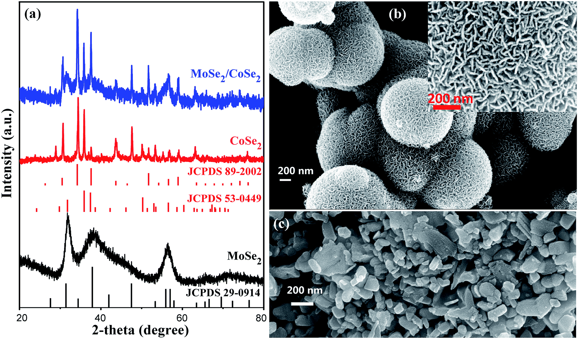 | ||
| Fig. 1 (a) XRD patterns of the as-synthesized pure MoSe2, CoSe2, and MoSe2/CoSe2 composite; (b) and (c) are SEM images of the as-synthesized pure MoSe2 and CoSe2, respectively. | ||
Fig. 2 shows SEM and TEM images related to the MoSe2/CoSe2 composite with various Mo/Co ratio. It can be observed that the synthesized MoSe2/CoSe2 composites demonstrate totally different morphologies from that of either MoSe2 or CoSe2 when using combinations of Co and Mo salts under the same reaction condition. The MC31 and MC11 products form hierarchical tube-like nanosheet-assembled microcage, (Fig. 2a and b). These microcages aggregate with a uniform size distribution, with an average diameter of 1.1 μm and length of 3.1 μm for MC31, and 1.65 μm and 3.37 μm for the MC11 compound. The MC13 with higher Co ratio evolves into an irregular shape, but still demonstrates a cage-like morphology (Fig. 2c). The detailed hierarchical structure of the MoSe2/CoSe2 composites is highlighted in the inset of Fig. 2b. The inner surface of the microcage is dense and smooth, while the external surface is composed by multi-fold nanosheets with a thickness of 5–10 nm. The elemental mapping characterization (Fig. S3†) shows a uniform distribution of both Mo and Co, indicating co-nucleation and crystallization of the MoSe2 and CoSe2 during the hydrothermal reaction. The co-growth mechanism leads to a thorough mix of MoSe2 and CoSe2 at nanoscale level, which can facilitate the synergic effect between MoSe2 and CoSe2 by inducing defects formation. What is interesting, the much more strong colour of Mo element in Fig. S3† may imply that MoSe2 prefer to grow on the surface of the microcage forming the nanosheets, while Co prone to crystalize in the inner part of the microtube. The formation of the unique hierarchical nanosheet-assembled microcage can be reasonably attributed to the competing nucleation and growth processes and different crystallization kinetics existing in molybdenum- and cobalt-based chalcogenides. Although the precise growth mechanism of the nanosheets assembled hierarchical microcage is not completely clear yet, the highly tunable structure induced by merely altering the Mo/Co ratio is a very encouraging evidence for further exploration of the Mo/Co hybrid nanocomposite.
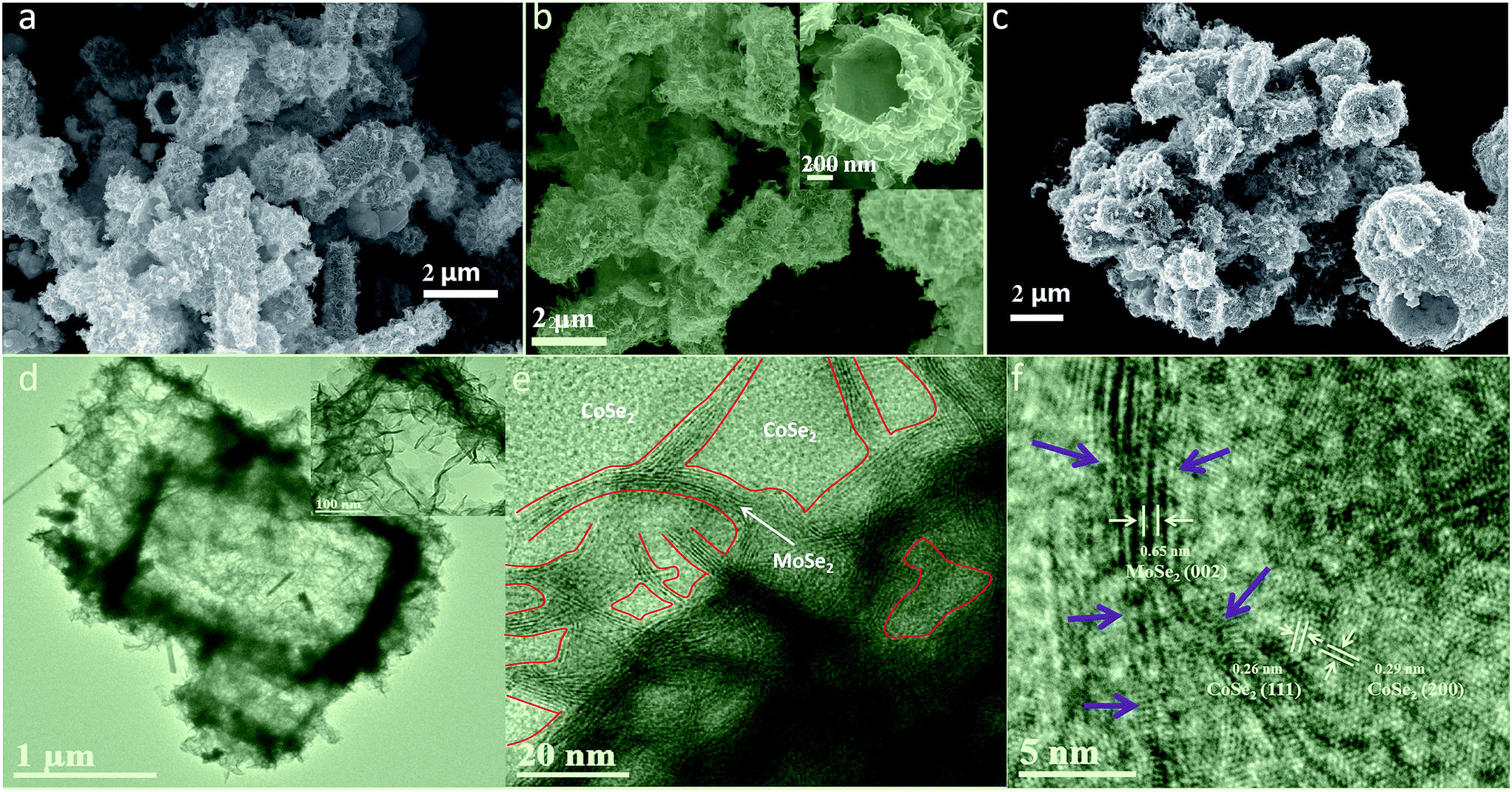 | ||
| Fig. 2 SEM images of MoSe2/CoSe2 composite with varied Mo/Co molar ratio: (a) Mo:Co = 3:1 denoted as MC31, (b) Mo:Co = 1:1 denoted as MC11, and (c) Mo:Co = 1:3 denoted as MC13. (d–f) are TEM and HRTEM of MC11. | ||
Fig. 2d–f shows TEM and HRTEM images related to the MC11 compound that further clarify the crystallography of the hierarchical MoSe2/CoSe2 microcages. The TEM image in Fig. 2d clearly shows the tube-like microcage with hierarchical structure. The HRTEM image in Fig. 2e gives evidence to the presence of microscopic phase formation with the [002] planes of the hexagonal MoSe2, the [111] planes of the orthorhombic CoSe2 and the [200] planes of the cubic CoSe2. Besides, the HRTEM shown in Fig. 2f features a clear narrow strip distribution of the MoSe2 phase in the main CoSe2. These results also prove that the MoSe2/CoSe2 composite is constituted by quasi-amorphous MoSe2 and polymorphic CoSe2, which is consistent with the findings from the XRD analysis. Besides, defects are also observed along the MoSe2 nano-strip. These defects act as active sites for HER, while the dense and smooth inner surface of the microcage improves significantly its conductivity.
To investigate the HER performance of the synthesized MoSe2/CoSe2 composite, the electrochemical measurements were carried out on the bare GC electrode in a 0.5 M H2SO4 solution using a typical three-electrode setup. For comparison, HER catalytic measurements using MoSe2, CoSe2, Pt and GC were also performed. All measurements were carried out at the same optimized loading weight of 0.285 mg cm−2. As shown in Fig. 3 and S4,† all the products related to the MoSe2/CoSe2 composites exhibit a superior HER performance when compared to the ones of the pristine MoSe2 and CoSe2. The onset overpotential (η) of MC11 is 110 mV, obviously lower than the 200 mV of the pure MoSe2, and the 140 mV of CoSe2. MC11 shows an extremely large cathodic current density of 90.4 mA cm−2 at η = 350 mV, which is 28 times larger than the one observed in MoSe2, and also larger than the 60.2 mA cm−2 observed in CoSe2. From Fig. S4a† it is quite evident that the cathodic current density of 90.4 mA cm−2 at η = 350 mV for MC11 is one of the best electrochemical performances of the MoSe2/CoSe2 composite catalysts, suggesting a superior HER activity of the MoSe2/CoSe2 catalyst when using the optimized composition. The corresponding Tafel plots of the above HER catalysts are shown in Fig. 3b and S4b,† in which the dotted line along the linear sections have been fitted according to the Tafel equation. The MoSe2/CoSe2 composite possesses smaller Tafel slopes (73 mV per dec for MC11, 85 mV per dec for MC31, and 93 mV per dec for MC13) than the ones typical of pure MoSe2 (144 mV per dec) and CoSe2 (95 mV per dec), therefore highlighting a faster increasing rate of H2 generation with increasing η values. The Tafel slope can also be adopted for the assessment of the rate-determining step in the HER process.49,79 In acidic medium, the whole HER process includes the following three steps. First, H+ is adsorbed onto the catalyst surface through a discharge step with Volmer reaction (H3O+ + e → Hads* + H2O, b ≈ 120 mV per dec, with b being the Tafel slope). Then the unstable Hads* migrates towards a more stable position on the catalyst surface with Spillover reaction: (Hads* → Hads, b ≈ 60 mV per dec). Finally, an electrochemical desorption step or a recombination step is needed to generate H2 generation with Heyrovsky reaction (Hads + H3O+ + e → H2 + H2O, b ≈ 40 mV per dec), or Tafel reaction (Hads + Hads → H2, b ≈ 30 mV per dec).79 The Tafel slope in the range of 73–93 mV per dec for the MoSe2/CoSe2 composite indicates that the Volmer or Spillover reaction may probably be the rate-determining step in the HER process.
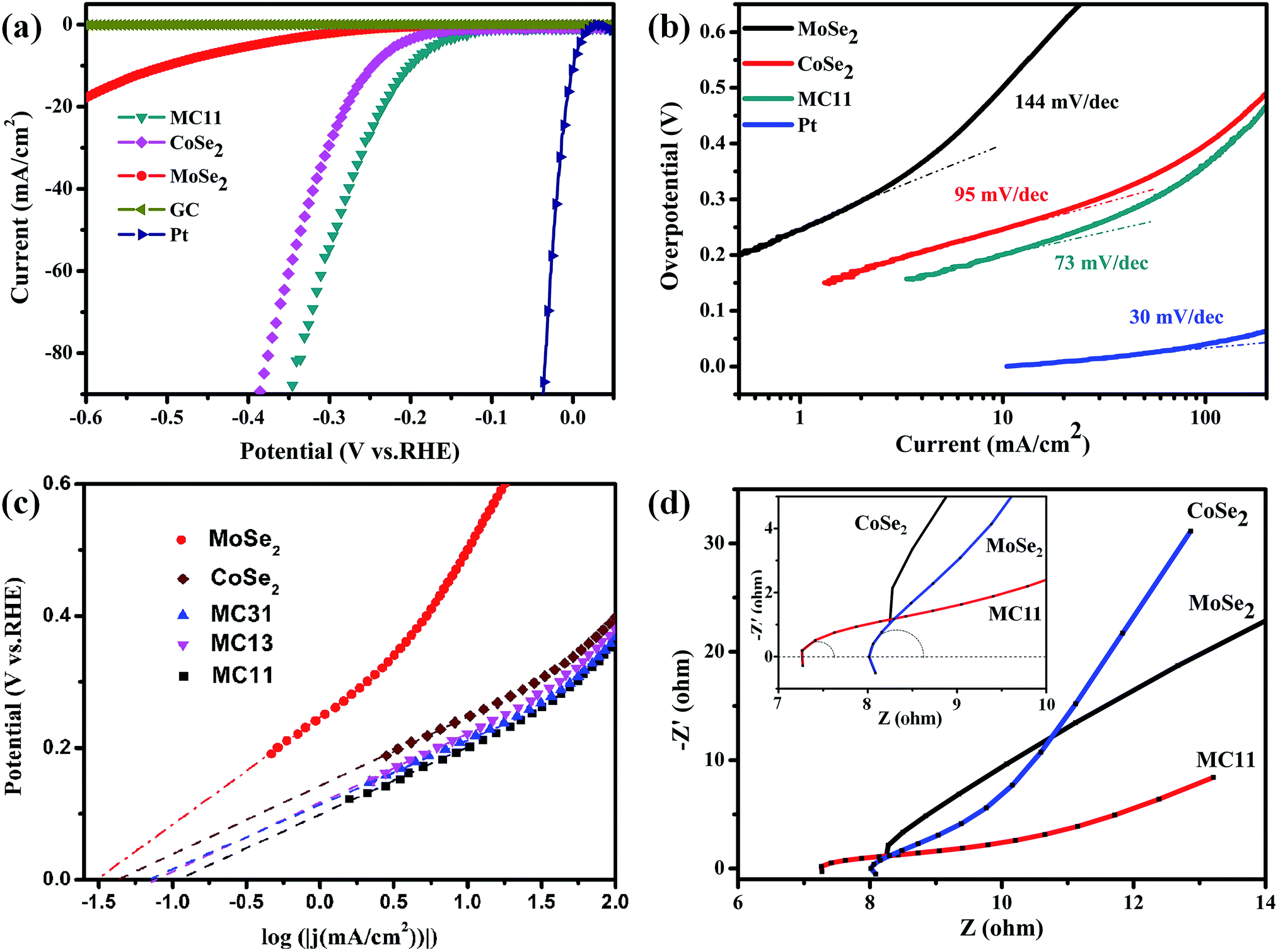 | ||
| Fig. 3 (a) Polarization curves and (b) corresponding Tafel plots of MoSe2, CoSe2, and MC11, respectively. The polarization and Tafel data derived from blank GC electrode and Pt were given for comparison. (c) Calculated exchange current densities of various samples by applying extrapolation method to the Tafel plots. (d) Nyquist plots of various samples. The partial circle data was fitted with the simplified Randles equivalent circuit6 using EC-lab software. | ||
By extrapolating the Tafel plots as shown in Fig. 3c it is possible to obtain the exchange current densities (j0). All the electrochemical parameters are summarized in Table 1. We can observe that MoSe2/CoSe2 exhibits larger exchange current density compared to the pristine MoSe2 and CoSe2. We should also note that, although CoSe2 exhibits a significantly better HER behaviour than the MoSe2, the MC13 compound with the highest CoSe2 proportion has the worst performance amongst all the MoSe2/CoSe2 composite catalysts. On the opposite, the MC11 with a medium Co content demonstrates a remarkable exchange current density of 117.5 μA cm−2, which is larger than the one obtained in the other compounds and almost 3.7 and 2.75 times larger than MoSe2 and CoSe2, respectively. The Nyquist plots of the EIS response provide further considerations about the electrode kinetics under HER. As can be observed from Fig. 3d and S4† all Nyquist plots consist of a tiny portion of circle plus a slash line. The charge-transfer resistance (RCT) and series resistance (RS) (as listed in Table 1) have been extracted from the Nyquist plots by fitting of the circle arc portion with the simplified Randles equivalent circuit6 using the EC-lab software. The data listed in Table 1 show a remarkable decrease of the RCT and RS in all the CoSe2/MoSe2 composite samples, which implies an enhancement of the inter-domain conductivity.6 In particular, the RCT decreases from 770 Ω to ∼2 Ω with the introduction of CoSe2 into MoSe2, and the improved conductivity is directly corresponding to the highly enhanced HER properties. We can therefore conclude that the enhancement of the HER activity observed in the MoSe2/CoSe2 composite can be attributed to its unique hierarchical morphology, as well as to the synergic effect between the MoSe2 and CoSe2 nanocomposites. The increased conductivity originated by the assembled microcages contributes to the larger cathodic current, and at the same time efficient active edge sites were induced by the hybridization of the MoSe2 and CoSe2 at nanoscale, which plays an important role in reducing the OP in the HER process.
| Materials | Onset OP [V] | Tafel slope [mV per dec] | Tafel region [mV] | Exchange current density, j0 [μA cm−2] | Cathodic current density, j300 [mA cm−2] | Charge-transfer resistance, RCT [Ω] | Series resistance, RS [Ω] |
|---|---|---|---|---|---|---|---|
| MoSe2 | −0.20 | 144 | 204–292 | 31.6 | 2.12 | 770 | 7.62 |
| CoSe2 | −0.14 | 95 | 152–268 | 42.7 | 30.09 | 6.57 | 8.06 |
| MC13 | −0.16 | 93 | 171–219 | 74.1 | 40.32 | 1.87 | 7.45 |
| MC31 | −0.l4 | 85 | 143–234 | 72.4 | 50.58 | 1.78 | 8.79 |
| MC11 | −0.11 | 73 | 157–227 | 117.5 | 56.0 | 1.88 | 7.33 |
Cycling stability has been tested by continuous cyclic voltammetry between −0.5 V and 0.2 V (vs. RHE) at 50 mV s−1 for 1000 cycles in 0.5 M H2SO4. As shown in Fig. 4, the current density of the as-synthesized tube-like MoSe2/CoSe2 composite nanosheets exhibits no obvious degradation, which suggests the presence of a good cycling performance and stability. The negligible degradation of the current density might be caused by the consumption of H+ or the remaining H2 bubbles on the surface of the catalyst, which hinder the reaction.28,49
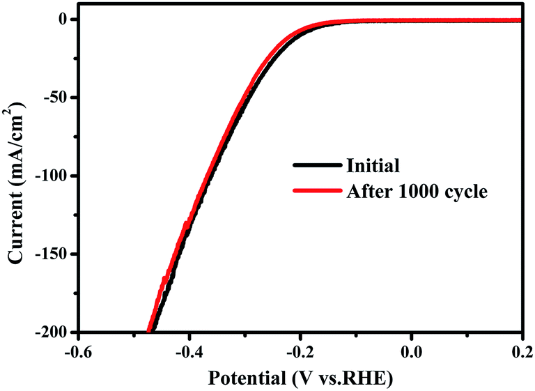 | ||
| Fig. 4 Cycling stability test of MC11 composite, suggesting a high durability for HER. | ||
Conclusion
We have explored the possibility of developing a facile one-pot hydrothermal method to synthesize hierarchical nanosheet-assembled MoSe2/CoSe2 microcages for electrocatalytic HER. Compared against pristine MoSe2 and CoSe2, the MoSe2/CoSe2 nanocomposite shows significantly enhanced HER catalytic activity with a lower onset overpotential of 75 mV, larger cathodic current, and a smaller Tafel slope. The improvement of the HER performance can be attributed to the increase of conductivity introduced via the nanosheets-assembled microcages, and the defects generated by the MoSe2/CoSe2 hybridization at nanoscale. The facile synthesis procedure and the easily controllable hierarchical structure generated open a new way to develop superior hybrid catalysts for HER.Acknowledgements
This work is financially supported by the National Natural Science Foundation of China grant no. 51402042 and 61106099, and the Fundamental Science on Nuclear Wastes and Environmental Safety Laboratory (no. 14zxnk04).Notes and references
- N. R. Elezović, L. Gajić-Krstajić, V. Radmilović, L. Vračar and N. V. Krstajić, Electrochim. Acta, 2009, 54, 1375–1382 CrossRef.
- W. Sheng, H. A. Gasteiger and Y. Shao-Horn, J. Electrochem. Soc., 2010, 157, B1529 CrossRef CAS.
- J. Kye, M. Shin, B. Lim, J. W. Jang, I. Oh and S. Hwang, ACS Nano, 2013, 7, 6017–6023 CrossRef CAS PubMed.
- S. A. Grigoriev, P. Millet and V. N. Fateev, J. Power Sources, 2008, 177, 281–285 CrossRef CAS.
- S. K. Srivastava, J. S. Del Río, C. K. O'Sullivan, C. Ogino and A. Kondo, RSC Adv., 2014, 4, 48458–48464 RSC.
- J. Xie, J. Zhang, S. Li, F. Grote, X. Zhang, H. Zhang, R. Wang, Y. Lei, B. Pan and Y. Xie, J. Am. Chem. Soc., 2013, 135, 17881–17888 CrossRef CAS PubMed.
- E. Casado-Rivera, D. J. Volpe, L. Alden, C. Lind, C. Downie, T. Vazquez-Alvarez, A. C. Angelo, F. J. DiSalvo and H. D. Abruna, J. Am. Chem. Soc., 2004, 126, 4043–4049 CrossRef CAS PubMed.
- D. Voiry, H. Yamaguchi, J. Li, R. Silva, D. C. Alves, T. Fujita, M. Chen, T. Asefa, V. B. Shenoy, G. Eda and M. Chhowalla, Nat. Mater., 2013, 12, 850–855 CrossRef CAS PubMed.
- D. Merki, S. Fierro, H. Vrubel and X. Hu, Chem. Sci., 2011, 2, 1262–1267 RSC.
- D. Merki and X. Hu, Energy Environ. Sci., 2011, 4, 3878–3888 CAS.
- H. Vrubel, D. Merki and X. Hu, Energy Environ. Sci., 2012, 5, 6136 CAS.
- J. Kim, S. Byun, A. J. Smith, J. Yu and J. Huang, J. Phys. Chem. Lett., 2013, 4, 1227–1232 CrossRef CAS PubMed.
- D. Kong, H. Wang, J. J. Cha, M. Pasta, K. J. Koski, J. Yao and Y. Cui, Nano Lett., 2013, 13, 1341–1347 CrossRef CAS PubMed.
- M.-R. Gao, Z.-Y. Lin, T.-T. Zhuang, J. Jiang, Y.-F. Xu, Y.-R. Zheng and S.-H. Yu, J. Mater. Chem., 2012, 22, 13662 RSC.
- Y. Yang, S. Wang, J. Zhang, H. Li, Z. Tang and X. Wang, Inorg. Chem., 2015, 2, 931–937 CAS.
- H. Zhang, L. Lei and X. Zhang, RSC Adv., 2014, 4, 54344–54348 RSC.
- A. I. Carim, F. H. Saadi, M. P. Soriaga and N. S. Lewis, J. Mater. Chem. A, 2014, 2, 13835 CAS.
- H. Vrubel and X. Hu, Angew. Chem., Int. Ed., 2012, 51, 12703–12706 CrossRef CAS PubMed.
- W. F. Chen, C. H. Wang, K. Sasaki, N. Marinkovic, W. Xu, J. T. Muckerman, Y. Zhu and R. R. Adzic, Energy Environ. Sci., 2013, 6, 943 CAS.
- W. F. Chen, K. Sasaki, C. Ma, A. I. Frenkel, N. Marinkovic, J. T. Muckerman, Y. Zhu and R. R. Adzic, Angew. Chem., 2012, 51, 6131–6135 CrossRef CAS PubMed.
- E. J. Popczun, J. R. McKone, C. G. Read, A. J. Biacchi, A. M. Wiltrout, N. S. Lewis and R. E. Schaak, J. Am. Chem. Soc., 2013, 135, 9267–9270 CrossRef CAS PubMed.
- P. Xiao, M. A. Sk, L. Thia, X. Ge, R. J. Lim, J.-Y. Wang, K. H. Lim and X. Wang, Energy Environ. Sci., 2014, 7, 2624–2629 CAS.
- X. Hu, B. S. Brunschwig and J. C. Peters, J. Am. Chem. Soc., 2007, 129, 8988–8998 CrossRef CAS PubMed.
- P. A. Jacques, V. Artero, J. Pecaut and M. Fontecave, Proc. Natl. Acad. Sci. U. S. A., 2009, 106, 20627–20632 CrossRef CAS PubMed.
- E. S. Andreiadis, P.-A. Jacques, P. D. Tran, A. Leyris, M. Chavarot-Kerlidou, B. Jousselme, M. Matheron, J. Pécaut, S. Palacin, M. Fontecave and V. Artero, Nat. Chem., 2012, 5, 48–53 CrossRef PubMed.
- Y. Shi, C. Hua, B. Li, X. Fang, C. Yao, Y. Zhang, Y.-S. Hu, Z. Wang, L. Chen, D. Zhao and G. D. Stucky, Adv. Funct. Mater., 2013, 23, 1832–1838 CrossRef CAS.
- Y. N. Ko, S. H. Choi, S. B. Park and Y. C. Kang, Nanoscale, 2014, 6, 10511–10515 RSC.
- J. Xie, H. Zhang, S. Li, R. Wang, X. Sun, M. Zhou, J. Zhou, X. W. Lou and Y. Xie, Adv. Mater., 2013, 25, 5807–5813 CrossRef CAS PubMed.
- Q. Ang, J. Yu and M. Jaroniec, J. Am. Chem. Soc., 2012, 134, 6575–6578 CrossRef PubMed.
- D. Chen, G. Ji, B. Ding, Y. Ma, B. Qu, W. Chen and J. Y. Lee, Nanoscale, 2013, 5, 7890–7896 RSC.
- J. Xie, S. Li, X. Zhang, J. Zhang, R. Wang, H. Zhang, B. Pan and Y. Xie, Chem. Sci., 2014, 5, 4615–4620 RSC.
- H. Chen, Y. Xie, H. Cui, W. Zhao, X. Zhu, Y. Wang, X. Lu and F. Huang, Chem. Commun., 2014, 50, 4475–4477 RSC.
- L. Cao, S. Yang, W. Gao, Z. Liu, Y. Gong, L. Ma, G. Shi, S. Lei, Y. Zhang, S. Zhang, R. Vajtai and P. M. Ajayan, Small, 2013, 9, 2905–2910 CrossRef CAS PubMed.
- M. Xu, T. Liang, M. Shi and H. Chen, Chem. Rev., 2013, 113, 3766–3798 CrossRef CAS PubMed.
- X. Huang, Z. Zeng and H. Zhang, Chem. Soc. Rev., 2013, 42, 1934–1946 RSC.
- Q. H. Wang, K. Kalantar-Zadeh, A. Kis, J. N. Coleman and M. S. Strano, Nat. Nanotechnol., 2012, 7, 699–712 CrossRef CAS PubMed.
- M. Chhowalla, H. S. Shin, G. Eda, L. J. Li, K. P. Loh and H. Zhang, Nat. Chem., 2013, 5, 263–275 CrossRef PubMed.
- X. Zhang and Y. Xie, Chem. Soc. Rev., 2013, 42, 8187–8199 RSC.
- J. Feng, X. Sun, C. Wu, L. Peng, C. Lin, S. Hu, J. Yang and Y. Xie, J. Am. Chem. Soc., 2011, 133, 17832–17838 CrossRef CAS PubMed.
- J. Xie, X. Sun, N. Zhang, K. Xu, M. Zhou and Y. Xie, Nano Energy, 2013, 2, 65–74 CrossRef CAS.
- L. Tao, X. Duan, C. Wang, X. Duan and S. Wang, Chem. Commun., 2015, 51, 7470–7473 RSC.
- D. Y. Chung, S.-K. Park, Y.-H. Chung, S.-H. Yu, D.-H. Lim, N. Jung, H. C. Ham, H.-Y. Park, Y. Piao, S. J. Yoo and Y.-E. Sung, Nanoscale, 2014, 6, 2131–2136 RSC.
- J. Kibsgaard, Z. Chen, B. N. Reinecke and T. F. Jaramillo, Nat. Mater., 2012, 11, 963–969 CrossRef CAS PubMed.
- T. F. Jaramillo, K. P. Jϕrgensen, J. Bonde, J. H. Nielsen, S. Horch and I. Chorkendorff, Science, 2007, 317, 100–102 CrossRef CAS PubMed.
- H. I. Karunadasa, E. Montalvo, Y. Sun, M. Majda, J. R. Long and C. J. Chang, Science, 2012, 335, 698–702 CrossRef CAS PubMed.
- B. Hinnemann, P. G. Moses, J. Bonde, K. P. Jorgensen, J. H. Nielsen, S. Horch, I. Chorkendorff and J. K. Norskov, J. Am. Chem. Soc., 2005, 127, 5308–5309 CrossRef CAS PubMed.
- J. Bonde, P. G. Moses, T. F. Jaramillo, J. K. Nørskovb and I. Chorkendorff, Faraday Discuss., 2008, 140, 219–231 RSC.
- V. W. Lau, A. F. Masters, A. M. Bond and T. Maschmeyer, Chemistry, 2012, 18, 8230–8239 CrossRef CAS PubMed.
- X. Zhou, J. Jiang, T. Ding, J. Zhang, B. Pan, J. Zuo and Q. Yang, Nanoscale, 2014, 6, 11046–11051 RSC.
- C. Tsai, K. Chan, F. Abild-Pedersen and J. K. Norskov, Phys. Chem. Chem. Phys., 2014, 16, 13156–13164 RSC.
- Y. Qu, H. Pan, C. Tat Kwok and Z. Wang, Phys. Chem. Chem. Phys., 2015, 17, 24820–24825 RSC.
- Y. Li, H. Wang, L. Xie, Y. Liang, G. Hong and H. Dai, J. Am. Chem. Soc., 2011, 133, 7296–7299 CrossRef CAS PubMed.
- Y. Liang, Y. Li, H. Wang and H. Dai, J. Am. Chem. Soc., 2013, 135, 2013–2036 CrossRef CAS PubMed.
- L. Liao, J. Zhu, X. Bian, L. Zhu, M. D. Scanlon, H. H. Girault and B. Liu, Adv. Funct. Mater., 2013, 23, 5326–5333 CrossRef CAS.
- D. Voiry, M. Salehi, R. Silva, T. Fujita, M. Chen, T. Asefa, V. B. Shenoy, G. Eda and M. Chhowalla, Nano Lett., 2013, 13, 6222–6227 CrossRef CAS PubMed.
- Z. H. Deng, L. Li, W. Ding, K. Xiong and Z. D. Wei, Chem. Commun., 2015, 51, 1893–1896 RSC.
- C. B. Ma, X. Qi, B. Chen, S. Bao, Z. Yin, X. J. Wu, Z. Luo, J. Wei, H. L. Zhang and H. Zhang, Nanoscale, 2014, 6, 5624–5629 RSC.
- H. Yuan, J. Li, C. Yuan and Z. He, ChemElectroChem, 2014, 1, 1828–1833 CrossRef CAS.
- S.-Y. Tai, C.-J. Liu, S.-W. Chou, F. S.-S. Chien, J.-Y. Lin and T.-W. Lin, J. Mater. Chem., 2012, 22, 24753 RSC.
- H. Tang, K. Dou, C.-C. Kaun, Q. Kuang and S. Yang, J. Mater. Chem. A, 2014, 2, 360–364 CAS.
- L. Jia, X. Sun, Y. Jiang, S. Yu and C. Wang, Adv. Funct. Mater., 2015, 25, 1814–1820 CrossRef CAS.
- X. Zhang, Y. Zhang, B.-B. Yu, X.-L. Yin, W.-J. Jiang, Y. Jiang, J.-S. Hu and L.-J. Wan, J. Mater. Chem. A, 2015, 3, 19277–19281 CAS.
- L. F. Pan, Y. H. Li, S. Yang, P. F. Liu, M. Q. Yu and H. G. Yang, Chem. Commun., 2014, 50, 13135–13137 RSC.
- Y. Wang, J. Tang, B. Kong, D. Jia, Y. Wang, T. An, L. Zhang and G. Zheng, RSC Adv., 2015, 5, 6886–6891 RSC.
- L. Wu, X. Wang, Y. Sun, Y. Liu and J. Li, Nanoscale, 2015, 7, 7040–7044 RSC.
- Y. Yan, X. Ge, Z. Liu, J.-Y. Wang, J.-M. Lee and X. Wang, Nanoscale, 2013, 5, 7768 RSC.
- Y. Huang, Y.-E. Miao, J. Fu, S. Mo, C. Wei and T. Liu, J. Mater. Chem. A, 2015, 3, 16263–16271 CAS.
- L. Yang, W. Zhou, D. Hou, K. Zhou, G. Li, Z. Tang, L. Li and S. Chen, Nanoscale, 2015, 7, 5203–5208 RSC.
- Y. Li, W.-q. Cao, J. Yuan, D.-w. Wang and M.-s. Cao, J. Mater. Chem. C, 2015, 3, 9276–9282 RSC.
- C. Meng, Z. Liu, T. Zhang and J. Zhai, Green Chem., 2015, 17, 2764–2768 RSC.
- S. Xu, Z. Lei and P. Wu, J. Mater. Chem. A, 2015, 3, 16337–16347 CAS.
- W. Zhou, D. Hou, Y. Sang, S. Yao, J. Zhou, G. Li, L. Li, H. Liu and S. Chen, J. Mater. Chem. A, 2014, 2, 11358 CAS.
- M. R. Gao, J. X. Liang, Y. R. Zheng, Y. F. Xu, J. Jiang, Q. Gao, J. Li and S. H. Yu, Nat. Commun., 2015, 6, 5982 CrossRef CAS PubMed.
- H. Wang, D. Kong, P. Johanes, J. J. Cha, G. Zheng, K. Yan, N. Liu and Y. Cui, Nano Lett., 2013, 13, 3426–3433 CrossRef CAS PubMed.
- F. H. Saadi, A. I. Carim, J. M. Velazquez, J. H. Baricuatro, C. C. L. McCrory, M. P. Soriaga and N. S. Lewis, ACS Catal., 2014, 4, 2866–2873 CrossRef CAS.
- Y. F. Xu, M. R. Gao, Y. R. Zheng, J. Jiang and S. H. Yu, Angew. Chem., 2013, 52, 8546–8550 CrossRef CAS PubMed.
- M. R. Gao, W. T. Yao, H. B. Yao and S. H. Yu, J. Am. Chem. Soc., 2009, 131, 7486–7487 CrossRef CAS PubMed.
- H. Zhang, B. Yang, X. Wu, Z. Li, L. Lei and X. Zhang, ACS Appl. Mater. Interfaces, 2015, 7, 1772–1779 CAS.
- C. Xu, S. Peng, C. Tan, H. Ang, H. Tan, H. Zhang and Q. Yan, J. Mater. Chem. A, 2014, 2, 5597–5601 CAS.
- W. A. Abdallah and A. E. Nelson, J. Mater. Sci., 2005, 40, 2679–2681 CrossRef CAS.
Footnotes |
| † Electronic supplementary information (ESI) available: XPS and EDX spectra of MC11, Tafel plots of various samples, and Nyquist plots of various samples are included. See DOI: 10.1039/c5ra21638a |
| ‡ These authors contribute equally. |
| This journal is © The Royal Society of Chemistry 2016 |