DOI:
10.1039/C5RA20781A
(Paper)
RSC Adv., 2015,
5, 100535-100545
Influence of Na+ ion doping on the phase change and upconversion emissions of the GdF3: Yb3+, Tm3+ nanocrystals obtained from the designed molecular precursors†
Received
7th October 2015
, Accepted 16th November 2015
First published on 17th November 2015
Abstract
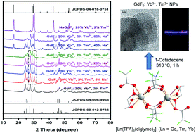
Bottom-up synthesis of a series of GdF3 nanocrystals (NCs) co-doped with 20 mol% Yb3+, 2 mol% Tm3+ and varying amount of Na+ ions is reported using novel molecular precursors [Ln2(TFA)6(diglyme)2] [Ln = Gd (1), Tm (2), Yb (3)] and [Na4(TFA)4(diglyme)]∞ (4) [TFA = CF3COO−; diglyme = MeO(CH2CH2O)2Me]. The single crystal X-ray structures of the new complexes 1–4, which act as excellent precursors because of the absence of water molecules and the ability of the diglyme ligand to behave as a capping reagent during decomposition to render the nanoparticles monodisperse in organic solvents, show a versatile bonding mode of the TFA (dangling η1 or bridging μ,η1,η1; μ4-η1:η1:η1:η1- and μ4-η1:η1:η1:η2 (O, F)) and diglyme (η3 or μ-η3:η1) ligands. The influence of Na+ ion doping on the phase change and upconversion emissions of these GdF3: Yb3+, Tm3+ NCs was studied and compared with the upconversion (UC) intensity of the well-known upconverting NaGdF4: Yb3+, Tm3+ NCs. Among the several UC samples studied, the GdF3: Yb3+, Tm3+ NCs with 30 mol% Na+ seemed to be the most promising as a red emitting UC phosphor, emitting more photons than the NaGdF4: Yb3+, Tm3+ UC NCs in the near IR region.
Introduction
The requirement for narrow emission profiles for several applications including those related to up-conversion or down-conversion has led to a huge interest in the lanthanide fluoride-based materials.1 Many of these lanthanide fluoride based nanomaterials (such as NaYF4, NaGdF4, GdF3, etc.) are considered as the most efficient host matrices for near-infrared-to-UV/visible upconversion, because of the low phonon energies of the fluorides, their optical transparency over a wide wavelength range, close lattice matching of the host lanthanide ions to the usual dopant Yb3+ and Er3+/Tm3+ ions and minimized quenching of the excited state, which favor attaining high fluorescent quantum efficiency.2 Among these, GdF3 nanoparticles (NPs) are also of interest as paramagnetic contrast agents in magnetic resonance imaging (MRI).3 The GdF3 NPs, either undoped or doped with lanthanide ions, have been obtained by several methods, ranging from microemulsion to hydrothermal method and sonochemical procedure.4 For this material, the orthorhombic phase is thermodynamically more stable at rt and, hence, is formed preferentially in most of the syntheses. The metastable hexagonal phase, which is many fold more efficient for the luminescence as compared to the orthorhombic phase, is stable only at high temperature.5 In recent times, metal ion doping has been used to modify the host matrices to control their shape and size, alter their crystalline phases and tune their luminescence.6 After Liu et al. demonstrated in 2010 the cubic-to-hexagonal phase transition simply by doping NaYF4 with larger Gd3+ cation,7 many reports have appeared describing doping-induced change in the structure and luminescent properties of the metal fluride-based nanomaterials.8–17 The alkali metal cations, in particular Li+ ion, seem to be preferred choice as a dopant because these can easily be accommodated in the host matrices due to their smaller ionic radii.6 Besides, few articles have also reported doping of either rare-earth metal cation (La3+) or alkaline-earth metal cations (Sr2+, Ca2+)8 in a lanthanide fluoride matrix to tailor the local crystal field around the lanthanide ions.9,10 A number of reports have described change in morphology, phase and/or crystal symmetry around Er3+/Tm3+ ion, accompanied by UC color tunability upon doping NaLnF4: Yb3+, Er3+/Tm3+ (Ln = Y, Gd, Yb) with Li+ or K+.11–15 In other reports, doping GdF3: Yb3+, Tm3+ or ErF3 NCs with Li+ had a negligible effect on the phase structure, though it did change the crystal symmetry around Er3+ ion, leading to change in UC emission color from yellow to red in the former and 4-fold enhancement in the emission in the later.16,17 One objective of this work was to investigate the influence of doping the matrix GdF3 with bigger alkali ion Na+ (r = 116 pm against 90 pm for Li+) and to see if this can transform the often as-prepared orthorhombic phase to the most efficient hexagonal phase. Indeed, due to comparable ionic radii of Na+ (116 pm) and Gd3+ (107.8 pm), the former would not only be accommodated easily in the GdF3 lattice, but is also expected to result in its expansion. This would decrease the repulsive forces between fluoride anions and hence would stabilize the hexagonal phase.
A bottom-up approach to nanomaterials, where a molecular compound containing the component element(s) is used in a chemical vapor deposition (CVD), metal–organic decomposition (MOD) or sol–gel process, facilitates a better control over the composition, structure and morphology of the nanomaterials.18 Thoughtful design of precursors and optimization of the ligand set require knowledge of the relationships between the properties of the materials and of their precursors.18 Unfortunately, this approach remains much less explored to obtain LnF3 nanomaterials, mainly due to unavailability of the suitable metallic precursors.19 Traditionally, lanthanide complexes with fluorinated acetylacetonates such as in situ synthesized anhydrous [Ln(hfac)3] (Ln = La, Y and/or Er; Hhfac = hexafluoro-2,4-pentanedione)20 or [Ln(hfac)3(glyme)] (Ln = a lanthanide; glyme = mono-, di-, tri-, or tetraglyme)21 have been used as volatile MOCVD precursors for the preparation of lanthanide fluorides and oxo-fluorides thin films. Generally speaking, the formation of competing fluoride phases is intimately associated with both thermodynamic stabilities and formation kinetics of the potential growing phases. Thus, LnF3 films could be deposited at atmospheric pressure and low temperature (up to 600 °C) from the precursor [Ln(hfac)3(diglyme)] (Ln = La,22 Pr,23 Gd,24 Ce25). The LnO1−xF1+2x (0 ≤ x ≤ 1) phase became more stable either upon increasing the temperature in the range 600–850 °C or at higher O2 flow. Similarly, the introduction of water vapor into the oxygen stream produced polycrystalline LnOF films (Ln = Pr, Gd and Eu).23,26 On the other hand, lanthanide trifluoroacetate precursors have been used to get lanthanide fluoride nanoparticles either by sol–gel process or thermolysis.19 Employing a mixed-ligand complex [Yb(TFA)2(OAc)(H2O)]·TFAH in fluorolytic sol–gel procedure, the formation of a transparent sol containing YbF3 NPs of about 5 nm size was recently reported.27 Single-crystalline and monodisperse LnF3 (Ln = La, Gd) nanoplates in trigonal structure were synthesized via thermolysis of [Ln(TFA)3(H2O)x] in a hot oleic acid/1-octadecene solution.28 The high uniformity of these nanoplates allowed the formation of nanoarrays arranged with long-range translational and orientational order in several microns. We have previously described anhydrous homo- and heterometallic Na–Ln complexes with trifluoroacetate and glyme ligands which behaved as excellent single source precursors and, on decomposition in 1-octadecene in inert atmosphere, gave upconverting NaY(Gd)F4: Yb3+, Er3+/Tm3+ or scintillating CeF3 nanocrystals.29,30 Extending this approach, we describe here structurally similar anhydrous lanthanide(III) trifluoroacetate complexes with diglyme ligand [Ln2(TFA)6(diglyme)2] [Ln = Gd (1), Tm (2), Yb (3)] as excellent precursors to obtain upconverting GdF3: Yb3+, Tm3+ NCs of sub-20 nm size. The absence of water molecule in these complexes not only avoid the risk of the formation of oxofluoride phases, but is also likely to enhance the luminescence by eliminating the possibility of the well-known quenching effect of water molecules retained on the surface of the resulting NPs. For doping the GdF3: Yb3+, Tm3+ NCs with Na+ ion, we synthesized another new precursor [Na4(TFA)4(diglyme)]∞ (4). Structurally characterized single source precursors for the NaF nanomaterials are scarce and limited to the first generation [Na4(ORf)4] [ORf = CH(CF3)2, C(CF3)3, C(CH3)(CF3)2, C(CH3)2(CF3)], [Na(hfac)] and [Na(fod)] (H-fod = heptafluoro-7,7-dimethyl-4,6-octanedione).31 These precursors (1)–(4) provide in situ the diglyme ligand, which would stabilize the formed nanoparticles and render them monodisperse in organic solvents by coordinating to the surface of the NPs and thereby preventing their agglomeration.
Results and discussions
(a) Synthesis
As mentioned in the introduction section, there is clearly a void of well-characterized molecular precursors for LnF3 and NaF nanomaterials. Lanthanide trifluoroacetate complexes are known to give LnF3 when decomposed in an inert atmosphere. However, a majority of the lanthanide trifluoroacetate complexes are hydrated and, as mentioned before, the presence of water molecules is detrimental for the luminescent properties of LnF3 NCs. The cost-efficient synthesis of lanthanide trifluoroacetate by reacting Ln2O3 with trifluoroacetic acid proceeds with the formation of water as a by-product to afford the hydrated complex Ln(TFA)3(H2O)3. However, efforts to get rid of water molecules in Ln(TFA)3(H2O)x by thermal dehydration have proved difficult.32 Another strategy to get anhydrous complexes is to use ancillary co-ligands in the reaction medium. Using this strategy, anhydrous polyether adducts of lanthanide hexafluoroacetylacetonates, [La(hfac)3(glyme)] (glyme = diglyme, triglyme, tetraglyme) were easily prepared through one-pot reactions of lanthanide oxides, hexafluoroacetylacetone (H-hfac) and polyether ligands in suitable solvents (benzene or dichloromethane).21 For the early lanthanides, however, monohydrated [Ln(hfac)3(monoglyme)(H2O)] (Ln = La,33 Nd34) were obtained with the monoglyme ligand and it was assumed that the bidentate monoglyme was not bulky enough to prevent a water molecule coordinating these large metals.21 A publication in 2012, however, reported syntheses of anhydrous [Ln(hfac)3(monoglyme)] (Ln = La, Ce, Pr, Sm, Eu, Gd, Tb, Dy, Er, Tm) and, thus, contradicted above assumption.35 We have previously demonstrated that the glyme ligands not only replace the water molecules of hydrated lanthanide trifluoroacetates to afford anhydrous precursors,29,30 but also stablize metal complexes by wrapping/shielding the metal cations efficiently and saturating their coordination spheres.36 These ligands also act as a surfactant during decomposition and, therefore, help getting nanoparticles with controlled size and desired dispersibility in organic media. The above findings prompted us to attempt a simple reaction of Ln2O3 with trifluoroecetic acid in THF in the presence of diglyme, which afforded anhydrous complexes [Ln2(TFA)6(diglyme)2] [Ln = Gd (1), Tm (2), Yb (3)] in excellent yield (eqn (1)). Alternatively, the derivatives (1)–(3) could also be synthesized by the reactions of Ln(TFA)3(H2O)x with diglyme in THF (see the Experimental section). We also synthesized another new precursor [Na4(TFA)4(diglyme)] (4) by reacting NaH with trifluoroecetic acid in THF in the presence of diglyme (eqn (2)) to dope the GdF3: Yb3+, Tm3+ NCs, obtained from the above precursors (1)–(3), with Na+ ion. |
 | (1) |
|
 | (2) |
(b) Structural characterization
Since the lanthanide complexes [Ln2(TFA)6(diglyme)2] [Ln = Gd (1), Tm (2), Yb (3)] are isostructural, only the gadolinium(III) complex (1) is described in detail here. The perspective figures for the Tm(III) and Yb(III) complexes and their selected bond lengths and angles (°) are given in ESI (Fig. S1 and S2†). The structure of 1 consists of discrete dinuclear molecules (Fig. 1). The Gd2(μ,η1,η1-TFA)4(η1-TFA)2 core has two different coordination modes for the TFA ligand, namely dangling and bridging bidentate. The neutral diglyme ligand binds in a tridentate fashion (η3-) to complete 8-coordination environment for the lanthanide centers, the geometry being distorted square antiprismatic. The Gd–O bond lengths range from 2.301(3) to 2.499(3) Å. As expected, the Gd-μ,η2-O(TFA) bonds [2.322(3)–2.395(3) Å] are longer than the corresponding Gd-η1-O(TFA) ones [2.301(3) Å]. The intramolecular Gd⋯Gd distance in the dimer is 4.542 Å. This dimeric structure can be related to those of [Y2(TFA)6(ROH)x] [where R = C2H4OPri (x = 4), C2H4OC2H4OMe (x = 2)] containing four μ-η1:η1-TFA ligands.37
 |
| Fig. 1 Perspective view of 1 with displacement ellipsoids drawn at the 30% probability level. H-atoms on diglyme ligand have been omitted for clarity. Selected bond lengths (Å) and angles (°): Gd1–O1 2.499 (3), Gd1–O6 2.375 (3), Gd1–O2 2.443 (3), Gd1–O8 2.395(3), Gd1–O4 2.301 (3), Gd1–O9 2.326 (3), O1–Gd1–O2 64.84(10), O2–Gd1–O4 105.79 (11), O1–Gd1–O3 111.26 (10), O6–Gd1–O8i 73.17 (12), O1–Gd1–O8 128.77 (11), O1–Gd1–O9i 153.28 (11), O3–Gd1–O4 76.64 (11), O6–Gd1–O9i 120.34 (11), O5–Gd1–O6 74.39(12), O6–Gd1–O1 71.39 (11), O6–Gd1–O4 137.21 (12), O2–Gd1–O5 145.96 (11). Symmetry code (i) −x + 1, −y + 1, −z + 1. | |
The asymmetric unit [Na4(TFA)4(diglyme)] in the 3D polymeric structure of 4 is associated with other such units via bridging trifluoroacetate and diglyme ligands (Fig. 2). The quarterly bridging TFA ligands, acting in two different manners, μ4-η1:η1:η1:η1- and μ4-η1:η1:η1:η2 (O, F)-, ensure the connectivity between different sodium centers. One doubly bridging μ-η3:η1-diglyme ligand between two sodium atoms further consolidates this assembly. The sodium metal centers have two different coordination environments. The 7-coordinate Na3, bound by three oxygen atoms of a diglyme ligand, one oxygen each from the three bridging TFA ligands and one short Na⋯F (2.928 Å), has a distorted pentagonal bipyramidal geometry. In contrast, the remaining three sodium centers Na1, Na2 and Na4 have a somewhat distorted octahedral geometry. While shorter Na⋯F distances (in the range 2.729–3.043 Å) help metal centers Na2 and Na4 to achieve an octahedral O4F2 environment around them, the metal center Na1 has all-oxygen environment around it, achieved by five O atoms of the bridging TFA ligands and one oxygen of a μ-η3:η1-diglyme ligand. The Na–O bond distances spread over the range 2.325(3)–2.577(4) Å and 2.232(3)–2.543(3) Å for 7- and 6-coordinated sodium centers, respectively. While the F⋯Na interaction and the bridging coordination mode of the diglyme ligand have previously been observed, for examples in cuban-shaped [Na4(ORf)4] [Rf = CH(CF3)2, C(CF3)3, C(CH3)(CF3)2, C(CH3)2(CF3)]31 and [Pb(hfac)2(μ-diglyme)]2 (ref. 38), respectively, the two bridging coordination modes of the TFA ligand namely μ4-η1:η1:η1:η1- and μ4-η1:η1:η1:η2 (O, F)-, as well as μ-η3:η1 mode of the diglyme ligand are reported here for the first time. It should be noted that on using excess of trifluoric acid, and in the absence of any ancillary co-ligand, sodium trifluoroacetate forms a 1D coordination polymer [Na(TFA)(TFAH)2]∞.39 The only other structurally characterized alkali metal trifluoroacetate complex with glyme ligand is [Li5(μ-TFA)5(μ-tetraglyme)2]∞, which also has both the ligands in bridging position to adopt a polymeric structure.40
 |
| Fig. 2 (a) Perspective view of 4 with displacement ellipsoids drawn at the 30% probability level, and (b) extended structure. H-atoms on diglyme ligand have been omitted for clarity. Selected bond lengths (Å) and angles (°): O1–Na3 2.577(4), O2–Na3 2.451(3), O3–Na1 2.543(3), O3–Na3 2.531(3), O4–Na1 2.416(3), O4–Na4 2.289(3), O5–Na1 2.438(3), O5–Na4 2.284(3), O6–Na1 2.379(3), O8–Na3 2.325(3), O7–Na1–O6 157.57(11), O6–Na1–O9 81.86(10), O7–Na1–O4 107.57(10), O6–Na1–O4 93.91(10), O9–Na1–O4 171.39(10), O6–Na1–O5 89.97(9), O4–Na1–O5 75.89(10), O7–Na1–O3 100.22(10), O7–Na2–O9 80.48(10), O7–Na2–O10 126.03(12), O9–Na2–O10 149.08(12), O7–Na2–F18 141.74(11), O9–Na2–F18 61.31(11), O8–Na3–O6 170.99(11), O8–Na3–O2 101.41(10), O2–Na3–O1 66.68(13), O3–Na3–O1 134.98(12), O4–Na4–O5 81.50(10), O4–Na4–F11 63.18(11), O5–Na4–F11 144.46(12), O4–Na4–O13 148.14(12), O5–Na4–O13 125.14(11), F11–Na4–O13 89.71(11). | |
(c) FT-IR spectra
The FT-IR spectra of 1–4 account for anhydrous species (absence of νOH absorptions in the region 3000–3500 cm−1) (Fig. S3†). The asymmetric and symmetric vibrations of νas (CO2) CO2 group are indicative of binding modes of a carboxylate ligand.41 When no consideration is given to the effect of the ancillary ligands attached to the metal centre in metal trifluoroacetates,42 a general order of the frequencies of the three binding modes of TFA ligand found in 1–4 can be given as νas (C
O bridging) > νas (C
O dangling) > (C
O chelating). For 1–3, two peaks at 1768 and 1692 cm−1 were observed, corresponding to the bridging and the dangling trifluoroacetate ligand, respectively. In contrast, appearance of a single peak at about 1680 cm−1 in 4 is consistent with only one type of TFA ligand present in this complex. Several characteristic absorption bands for TFA ligand such as C–F and C–O stretching in the 1120–1210 cm−1 range and C–C, C–F and C
O deformation in the 850–720 cm−1 region also characterize the spectra of 1–4.42 The low frequency absorptions at 632–404 cm−1 are due to the ν M–O vibrations. These FT-IR spectra, along with the elemental analysis data, indicate that the bulk powders of 1–4 are consistent with the single crystal structures described in the previous subsection.
(d) Thermogravimetric analysis
The thermal behavior of the new precursors 1–4 was investigated under argon atmosphere in the 20–600 °C temperature range by thermogravimetry (TG) and differential thermal analysis (DTA) (Fig. 3). The TGA curves of lanthanide derivatives 1–3 show two-step decomposition under argon atmosphere that lasts up to 310 °C. These compounds decompose continuously in the first step (120–200 °C) that corresponds to partial loss of the diglyme ligand (∼10.5% observed loss vs. ∼21% calculated loss for complete removal of the ligand). The second step, which is also the major step (53–55% weight loss in the range 200–325 °C) corresponds mainly to thermal decomposition of the TFA ligands, as indicated by a prominent exothermic peak at 308 °C in the differential thermal (DT) curve, along with the loss of remaining diglyme ligand. The remaining weight of the residues (34.8–36.9%) is consistent with the formation of LnF3 (34.0–35.6%) as the end product. This pattern of decomposition is supported by the DTA curves, which show endothermic peak at 175–185 °C for the partial removal of the diglyme molecule and a prominent exothermic peak at 285–295 °C for the decomposition of TFA ligands (Fig. S4†). The sodium derivative 4 shows similar two-step decomposition, though endo- and exo-thermic peaks in its DTA are shifted to lower temperature at 108 and 260 °C, respectively. This compound decomposes continuously in the first step (125–225 °C) and looses about 20% of the total mass, the second step being in the temperature range 225–275 °C (52.5% weight loss). The remaining residue weight (28%) accounts a little more than the expected yield of NaF materials (24.8%), which indicates incomplete decomposition due to the presence of argon atmosphere.
 |
| Fig. 3 TGA curves of (1)–(4). | |
(e) Preparation and characterization of GdF3: Yb3+, Tm3+ nanocrystals doped with different mol% of Na+ ion
As expected, the homometallic 1–3 act as excellent single source precursors for getting LnF3 nanocrystals. Following the TG-DTA profile of 1–3 described above, a decomposition temperature 310 °C and 1-octadecene (bp 315 °C) as the solvent medium were chosen for the decomposition. These precursors provide in situ the coordinating diglyme ligand, which acts as a surfactant to control the size of the LnF3 NCs as well as renders them monodisperse in the organic media. To obtain the host matrix GdF3 NCs co-doped with 20 mol% Yb3+ and 2 mol% Tm3+ cations, the derivatives 1, 2 and 3 were taken in appropriate amounts and then decomposed simultaneously in 1-octadecene. The XRD pattern of the as-prepared GdF3: Yb3+, Tm3+ NCs shows well-crystallized sample with all the peaks indexing well with the orthorhombic phase of the GdF3 NCs (JCPDS: 012-0788) (Fig. 4). No other phase was observed. An average nanocrystallite size of 20 nm was calculated from the Scherrer formula. The presence of diglyme ligand on the surface of these as-prepared NCs was confirmed by the FT-IR spectrum and the TG-DTA studies (Fig. S5 and S6†), which make the obtained NCs well-dispersed in organic solvents such as C7H8, CH2Cl2 and DMSO. One objective of this work was to see the influence of Na+ doping on the phase change and upconversion emissions of the GdF3: Yb3+, Tm3+ nanocrystals. To achieve this, a stock solution containing a fixed ratio of Gd, Yb and Tm precursors (100
:
20
:
2) was taken, mixed with varying amount of the sodium precursor [Na4(TFA)4(diglyme)] (4) and decomposed simultaneously in 1-octadecene to have GdF3: Yb3+, Tm3+ samples containing 5, 10, 20, 30, 40 and 80 mol% of Na+ ion. The incorporation of Na+ dopant ions into the host GdF3 crystal lattices leads to the formation of solid-solutions. As exhibited by the XRD patterns (Fig. 4, S7–S9†), with increasing Na+ content the host matrix GdF3 transforms from the orthorhombic phase to the hexagonal one (JSPDS: 04-006-9968). On increasing the Na+ content from 20 mol% to 30 mol%, the hexagonal phase increases from 12% to 36%. At 30 mol% Na+, however, a small amount of NaGdF4 phase (JCPDS: 04-018-0751) also appears, which increases further on increasing the Na+ content. Thus, at 40 mol% Na+, the relative percentages of the 3 phases namely hexagonal GdF3, orthorhombic GdF3 and hexagonal NaGdF4 are ∼14, 58 and 28%, respectively, which changes to ∼16, 46 and 38%, respectively, at 80 mol% Na+ (as calculated from the Reference Intensity Ratio (RIR) method).
 |
| Fig. 4 Powder XRD patterns of GdF3: Yb3+, Tm3+ NCs doped with different percentages of Na+ ion. The magnified XRD diffraction peaks on right hand side show gradual increase in the intensity of the hexagonal phase on increasing the concentration of the Na+ ion. | |
The high resolution transmission electron microscopy (HR-TEM) images of the as-prepared GdF3: Yb3+, Tm3+ show crystalline flakes of the nanometric size (Fig. 5, S10†). The high resolution TEM images of the as-prepared single flakes clearly show lattice fringes indicating high crystallinity and further confirming the orthorhombic phase of these GdF3 nanocrystals (Fig. 5a). The presence of dopant lanthanide ions Yb3+ and Tm3+ was confirmed by the EDX analysis. Even though highly crystalline, it was not possible to calculate correctly the interreticular distances on some occasions due to the overlapping of these nanoflakes (Fig. 5b). Formation of such nanoflakes have been shown previously in the case of LnF3 (Ln = La, Gd).28 It was found that the sole use of oleic acid (OA) or 1-octadecene (ODE) resulted in less uniform and ill-shaped nanoplates, while the use of a 1
:
1 mixture of OA and ODE led to uniform LnF3 triangular/rhombic nanoplates which self-assembled displaying long-range orientational and positional order.
 |
| Fig. 5 HR-TEM images of as-prepared GdF3: Yb3+, Tm3+ nanoflakes with associated FFTs shown in the inset. | |
(f) Upconversion studies
The up-conversion emission spectra of GdF3: Yb3+, Tm3+ nanocrystals doped with different percentages of Na+ ion were recorded in solid state under 980 nm laser diode excitation (with an intensity of 73 W cm−2) (Fig. 6). The emission bands in these spectra can easily be assigned to the transitions within the 4f–4f levels of the Tm3+ ions in the GdF3 host. These show classical blue and violet bands of the Tm3+ ion at about 480 nm (1G4 → 3H6), 460 nm (1D2 → 3F4) and 370 nm (1D2 → 3H6) as well as red emissions at about 650 nm (1G4 → 3F4) and 695 nm (1D2 → 3H4 and 3F3 → 3H6). As described in the previous subsection, these samples have three different phases of the matrixes, namely hexagonal GdF3, orthorhombic GdF3 and hexagonal NaGdF4, which have different upconversion efficiencies and processes. When the samples have Na+ ion doping level below 20 mol%, they are dominated by the orthorhombic phase and we observe a regular increase of the efficiency of the upconversion with the gradual addition of the Na+ ion. The spectra for this phase are very specific with a double peak at 680–705 nm and another at 480–486 nm. For the two other phases, i.e., hexagonal GdF3 and hexagonal NaGdF4, these peaks are merged into a single broad peak. The sample doped with 30 mol% Na+ ion has the hexagonal phase of GdF3 as high as 36% and shows the dominance of the band at 705 nm in the upconversion spectra for a fixed intensity. This phase also exhibits a strong saturation of the higher excited states even at 20 W cm−2. This saturation occurs only at 60 W cm−2 for the orthorhombic phase and is above 100 W cm−2 for the hexagonal phase of NaGdF4. For the two phases of GdF3 (orthorhombic and hexagonal), peaks above 680 nm show a power of 2 dependence of their upconversion luminescence while those below (370 nm up to 660 nm) show a power of three dependence until the saturation and then a power of 2 dependence (Fig. S11–S13†). The higher energy emitting energy levels come from 1G4 or above energy levels of Tm3+ and thus need three or more photons to be populated. In the case of the hexagonal phase of NaGdF4, the 1G4 level can easily be populated with two photons (Fig. S14†) since there can be cooperative sensitization and energy transfer up-conversion because of a better matching of the energy of 3H6 → 1G4 with the energy of two excited Yb3+ ions. Although less efficient for blue or UV emission, the GdF3: Yb3+, Tm3+ with 30 mol% Na+ could be an interesting red emitting upconversion phosphor, much desired for the biological applications where an emission in the red-near IR is more easily detectable. Fig. 6 shows that there are more photons emitted by it in the near IR than by the NaGdF4: Yb3+, Tm3+, which is supposed to be one of the best upconverting systems. In the case of hexagonal GdF3, a strong saturation appears in the variation of the intensity at around 40–50 W cm−2 for the 458 (1D2 → 3F4), 482 (1G4 → 3H6) and 654 nm (1G4 → 3F4) transitions, but the 704 nm transition (3F3 → 3H6) is not affected. So it is reasonable to imagine that for high intensity, some cross relaxation processes would depopulate the 1G4 and 1D2 at the expense of 3F3, 3F2 and 3H4 levels (Fig. 7). Compared to the matrix NaGdF4, where these cross relaxations are not present, the emission in the near IR will be relatively stronger while the emission from the higher energy states is weaker. It is worth noting that no appreciable difference was found in the upconversion intensity of the doped NaGdF4: Yb3+, Tm3+ nanoparticles prepared by using two different sets of the precursors, i.e. earlier reported single source precursors [NaLn(TFA)4(diglyme)] (Ln = Gd, Tm, Yb)29a or a mixture of [Ln2(TFA)6(diglyme)2] (Ln = Gd, Tm, Yb) and [Na4(TFA)4(diglyme)] described in this paper, most probably due to the similarity in the ligand set (TFA and diglyme) and the coordination environment around the metal centres (8- and 7-coordinated Ln3+ and Na+, respectively).
 |
| Fig. 6 Emission spectra of GdF3: Yb3+, Tm3+ NCs doped with different mol percentages of Na+ ion. | |
 |
| Fig. 7 Schematic energy level diagram showing all the observed transitions of Tm3+ and different energy transfer and cross relaxation processes. | |
Experimental
General procedures
The syntheses and decomposition of the precursors 1–4 were carried out under argon using Schlenk tube and vacuum line techniques. Solvents were purified on an MB SPS-800 instrument. Ln(TFA)3(H2O)3 (Ln = Gd, Tm, Yb) were prepared by reacting the Ln2O3 with trifluoroacetic acid in refluxing toluene, followed by an extraction with tetrahydrofuran (THF). Trifluoroacetic acid (TFAH) and diglyme (both Aldrich) were stored over molecular sieves, whereas 1-octadecene (Aldrich) was used as received. Analytical data were obtained from the Service Central d'Analyses du CNRS. FT-IR spectra of the derivatives 1–4 (as Nujol mulls) and nanoparticles (as KBr pallets) were recorded on a Bruker Vector 22 spectrometer. The TG-DTA data of 1–4 were collected in argon atmosphere (flow rate 50 cm3 min−1, thermal ramp 5 °C min−1, temperature range 20–600 °C) using a SETSYS Evolution-12 thermal analyzer. The TG-DTA data of the nanoparticles were collected in air (flow rate 50 cm3 min−1, thermal ramp 5 °C min−1, temperature range 20–600 °C). Upconverting studies were made on a homemade spectrofluorimeter. The samples were irradiated by a 980 nm and 300 mW laser diode driven by a LDC205C Laser Diode Controller and TED 200C Laser Diode Temperature Controller (both from Thorlabs, Inc) and the up-converted light was collected by an optical fiber feeding a Jobin Yvon TRIAX 320 monochromator equipped with a R2949 photomultiplier (PM) from Hamamatsu. The laser was focused on the sample down to a size of 150 μm radius spot and the fluence was varied by using neutral optical density filters.
Synthesis of new complexes
Method A for the synthesis of (1)–(3).
[Gd2(TFA)6(diglyme)2] (1). A reaction mixture containing Gd2O3 (1.10 g, 3.03 mmol), trifluoroacetic acid (1.5 mL, 19.6 mmol) and diglyme (0.5 mL, 3.5 mmol) in THF (20 mL) was refluxed for 12 h. After volatiles were removed under vacuum, the product was extracted with THF (10 mL). This THF solution was concentrated up to 4 mL and layered carefully with 8 mL of diethyl ether, which afforded colourless plate-like crystals. Yield, 3.1 g (81%). Anal. calcd for C24H28F18Gd2O18 (1260.96): C, 22.84; H, 2.22; found: C, 23.01; H, 2.29%. FT-IR (Nujol, cm−1): 1742s, 1697s (νasCO2), 1591w, 1468s, 1460w, 1421s, 1384w, 1356w, 1300w, 1220s, 1152s, 1094s, 1058s, (νC–F, νC–O), 1022m, 1012m, 943w, 874s, 847s, 835m, 802s, 727s, 615m, 602m, 522m, 458w, 439m.By adopting the similar procedure as described for 1, complexes 2 and 3 were also synthesized using appropriate quantity (given in parentheses) of Ln2O3, TFAH and diglyme in THF and crystallized by layering the THF solution with Et2O.
[Tm2(TFA)6(diglyme)2] (2). Tm2O3 (0.95 g, 2.46 mmol), TFAH (1.30 mL, 17.0 mmol) and diglyme (0.5 mL, 3.5 mmol) in 20 mL of THF. Yield, 2.43 g (77%). Anal. calcd for C24H28F18O18Tm2 (1284.44): C, 8.78; H, 2.32. Found: C, 8.83; H, 2.35%. FT-IR (Nujol, cm−1): 1754s, 1698s (νasCO2), 1591w, 1487s, 1461w, 1429s, 1377w, 1360w, 1300w, 1214s, 1151s, 1103w, 1093s, 1044s, (νC–F, νC–O), 1024m, 1012m, 946w, 889s, 857s, 837m, 812w, 803s, 728s, 667w, 619m, 605m, 552w, 523m, 463w, 444m.
[Yb2(TFA)6(diglyme)2] (3). Yb2O3 (0.8 g, 2.03 mmol), TFAH (1 mL, 13.1 mmol) and diglyme (0.5 mL, 3.5 mmol) in 20 mL of THF. Yield, 2.28 g (87%). Anal. calcd for C24H28F18O18Yb2 (1292.54): C, 22.28; H, 2.17. Found: C, 22.35; H, 2.21%. FT-IR (Nujol, cm−1): 1755s, 1700s (νasCO2), 1589w, 1485s, 1459w, 1430s, 1378w, 1361w, 1302w, 1217s, 1149s, 1100w, 1095s, 1041s, (νC–F, νC–O), 1021m, 1010m, 946w, 890s, 860s, 838m, 810w, 804s, 730s, 665w, 620m, 605m, 551w, 520m, 460w, 447m.
Method B for the synthesis of (1)–(3).
[Gd2(TFA)6(diglyme)2] (1). In a solution of Gd(TFA)3(H2O)x (2.0 g, 3.63 mmol) in 30 mL of THF, diglyme (0.52 mL, 3.65 mmol) was added drop wise and the resulting solution was stirred for 2 h at room temperature. Solution was concentrated up to 3 mL and layered carefully with 6 mL of diethyl ether. Colourless plate-like crystals grew overnight. Yield, 2.1 g (90%). The elemental analysis and FT-IR spectrum were consistent with the same product isolated by the method A.By adopting the similar procedure as described for 1, complexes 2 and 3 were also synthesized using appropriate quantity (given in parentheses) of Ln(TFA)3(H2O)x and diglyme in THF and crystallized by layering the THF solution with Et2O. Their elemental analyses and the FT-IR spectra were consistent with the same products isolated by the method A.
[Tm2(TFA)6(diglyme)2] (2). Tm(TFA)3(H2O)x (1.51 g, 2.69 mmol) and diglyme (0.39 mL, 2.71 mmol) in 20 mL of THF. Yield, 1.38 g (80%).
[Yb2(TFA)6(diglyme)2] (3). Yb(TFA)3(H2O)x (1.66 g, 2.94 mmol) and diglyme (0.42 mL, 2.93 mmol) in 20 mL of THF. Yield, 1.57 g (83%).
[Na4(TFA)4(diglyme)] (4). Diglyme (0.91 mL, 6.35 mmol) was added drop wise to a freshly prepared THF solution (10 mL) of NaTFA [NaH (0.553 g, 22.21 mmol) and TFAH (1.76 mL, 23.0 mmol)], and the resulting solution was stirred for 5 h at room temperature. Solution was concentrated up to 3 mL and layered carefully with 10 mL of diethyl ether. Colourless crystals grew overnight. Yield, 3.55 g (91%). Anal. calcd for C14H14F12Na4O11 (678.2): C, 24.77; H, 2.06. Found: C, 24.87; H, 2.10%. FT-IR (Nujol, cm−1): 1684s (νasCO2), 1474w, 1447s, 1381w, 1358m, 1213s, 1183s, 1142s, 1108s, 1080s (νC–F, νC–O), 1035w, 1018m, 944w, 868m, 845s, 805s, 727s, 600w, 517m, 448w, 411w.
X-ray crystallography
Suitable crystals of 1–4 were obtained as described in the Experimental section. Crystal structure of the compound 1–3 were measured using Mo radiation (λ = 0.71073 Å) on an Oxford Diffraction Gemini diffractometer equipped with an Atlas CCD detector. Intensities were collected at 100 K (for 1) or 160 K (for 2 and 3) by means of the CrysalisPro software.43 Reflection indexing, unit-cell parameters refinement, Lorentz-polarization correction, peak integration and background determination were carried out with the CrysalisPro software.43 An analytical absorption correction was applied using the modeled faces of the crystal.44 The resulting sets of hkl were used for structure solutions and refinements. The structures were solved by direct methods with SIR97 (ref. 45) and the least-square refinement on F2 was achieved with the CRYSTALS software.46 The crystal structure of 4 was measured on a Nonius Kappa CCD diffractometer. Intensities were collected at 150 K by means of the program COLLECT.47 Reflection indexing, Lorentz-polarisation correction, peak integration and background determination were carried out with the DENZO48 program. Frame scaling and unit-cell parameters refinements were made through the program SCALEPACK.48 Absorption corrections were achieved with the program DIFABS.49 The structures were solved by direct methods with SIR97.50 All non-H atoms were refined anisotropically. The structure refinement was carried out with CRYSTALS.46 Some selected crystallographic and refinement data of 1–4 are listed in Table 1.
Table 1 Crystallographic and refinement data for (1)–(4)
Compound |
1 |
2 |
3 |
4 |
Empirical formula |
C24H28F18Gd2O18 |
C24H28F18O18Tm2 |
C24H28F18O18Yb2 |
C14H14F12Na4O11 |
Formula weight |
1260.96 |
1284.44 |
1292.54 |
678.19 |
Crystal system |
Triclinic |
Triclinic |
Triclinic |
Triclinic |
Space group |
P![[1 with combining macron]](https://www.rsc.org/images/entities/char_0031_0304.gif) |
a (Å) |
8.8390(8) |
8.8422(7) |
8.8369(5) |
10.769(5) |
b (Å) |
9.3516(6) |
9.6242(7) |
9.6401(6) |
11.261(5) |
c (Å) |
13.4022(10) |
13.2522(8) |
13.2137(7) |
12.310(5) |
α (°) |
70.942(7) |
69.579(6) |
69.577(5) |
76.890(5) |
β (°) |
74.685(8) |
74.832(6) |
74.812(5) |
77.650(5) |
γ (°) |
76.421(7) |
72.913(7) |
72.774(5) |
74.503(5) |
V (Å3) |
996.41(14) |
994.16(13) |
991.63(11) |
1382.3(6) |
Z |
1 |
1 |
1 |
2 |
μ (mm−1) |
3.45 |
4.59 |
4.84 |
0.23 |
Temperature (K) |
100 |
160 |
160 |
150 |
Measured reflections |
26 450 |
26 607 |
52 157 |
5486 |
Independent reflections |
5102 |
5123 |
5185 |
5486 |
Data/restrains/parameters |
5083/42/308 |
5112/42/308 |
5173/48/308 |
3555/79/424 |
Goodness of fit |
0.99 |
0.97 |
1.04 |
1.14 |
R[F2 > 2σ(F2)] |
0.034 |
0.042 |
0.043 |
0.063 |
wR(F2) |
0.091 |
0.094 |
0.097 |
0.068 |
Residual electron density (e Å−3) |
−2.42 to 3.06 |
−2.09 to 1.36 |
−1.65 to 1.65 |
−0.77 to 0.66 |
Synthesis of GdF3: Yb3+, Tm3+ nanocrystals
The carefully weighed amounts of [Gd2(TFA)6(diglyme)2] (0.95 g, 0.75 mmol), [Yb2(TFA)6(diglyme)2] (0.19 g, 0.15 mmol) and [Tm2(TFA)6(diglyme)2] (0.02 g, 0.015 mmol) with an elemental ratio of Gd
:
Yb
:
Tm = 100
:
20
:
2 were taken in 15 mL of THF in a Schlenk under argon atmosphere. The resulting solution was stirred for 10 min to get a homogeneous solution of the three precursors. The THF was then removed under vacuum and 10 mL of 1-octadecene was added. This reaction mixture was then heated gradually at a rate of 10 °C min−1 under argon. After refluxing at 310 °C for 1 h, the mixture was allowed to cool to room temperature and light brown powder was precipitated by adding ethanol and isolated via centrifugation. The obtained NCs were then washed twice by dispersing in ethanol, isolated by centrifugation and dried in an oven at 70 °C for 24 h.
Synthesis of GdF3: Yb3+, Tm3+ nanocrystals doped with Na+ ion
To make sure that the relative ratio of Gd3+, Yb3+ and Tm3+ does not change in different samples, a stock solution containing [Gd2(TFA)6(diglyme)2] (5.36 g, 4.25 mmol), [Yb2(TFA)6(diglyme)2] (1.06 g, 0.82 mmol) and [Tm2(TFA)6(diglyme)2] (0.11 g, 0.085 mmol) with an elemental ratio of Gd
:
Yb
:
Tm = 100
:
20
:
2 was prepared in 500 mL THF and kept under argon atmosphere. To prepare GdF3: Yb3+, Tm3+ nanocrystals doped with 5 mol% Na+ ion, 50 mL of this stock solution was mixed with the sodium precursor [Na4(TFA)4(diglyme)] (0.007 g, 0.01 mmol) and after stirring for 30 min, the volatiles were removed under vacuum. The solid obtained was taken in 10 mL of 1-octadecene and refluxed at 310 °C for 1 h. After cooling the reaction mixture to room temperature, a light brown powder was precipitated by adding ethanol and isolated via centrifugation, washed twice with ethanol and dried in an oven at 70 °C for 24 h.
Following similar method, other GdF3: Yb3+, Tm3+ samples containing 10, 20, 30, 40, 80 and 100 mol% of Na+ ion were prepared by mixing the above stock solution with varying amount of the sodium precursor (4) and decomposed them in 1-octadecene.
Conclusions
We described here well-characterized Ln(III) trifluoroacetate complexes obtained in anhydrous form by a facile reaction between Ln2O3 with excess of trifluoroacetic acid in THF in the presence of diglyme. These complexes were then used as facile precursors to get upconverting GdF3: Yb3+, Tm3+ nanoflakes. The diglyme ligand, provided in situ by the precursors during the decomposition, coordinates strongly to the surface of LnF3 NPs and thereby leads to the stabilisation of the nanoparticles by preventing agglomeration and rendering them disperse in organic solvents. These easy-to-prepare complexes not only fill the void of well-characterized molecular precursors for LnF3 and NaF nanoparticles, but also allow precise control on the homogeneous doping which has profound effect on the upconversion (UC) properties of the resulting nanoparticles. The influence of Na+ ion doping on the phase change and upconversion emissions of these GdF3: Yb3+, Tm3+ NCs was studied and compared with the upconversion intensity of the well-known upconverting NaGdF4: Yb3+, Tm3+ NCs. Although less efficient for blue or UV emission, the GdF3: Yb3+, Tm3+ NCs doped with 30 mol% Na+ looked the most promising as red emitting UC phosphor, emitting more photons than the well-known NaGdF4: Yb3+, Tm3+ UC NCs in the near IR region.
Acknowledgements
One of the authors (WF) thanks the China Scholarship Council (CSC, file No. 201406740019) for the doctoral fellowship. They also acknowledge Y. Aizac and F. Bosselet (PXRD) as well as L. Burel (TEM) of IRCELYON for providing scientific services.
Notes and references
-
(a) M. Leblanc, V. Maisonneuve and A. Tressaud, Chem. Rev., 2015, 115, 1191 CrossRef CAS PubMed;
(b) P. P. Fedorov, A. A. Luginina, S. V. Kuznetsov and V. V. Osiko, J. Fluorine Chem., 2011, 132, 1012 CrossRef CAS.
-
(a) F. Auzel, Chem. Rev., 2004, 104, 139 CrossRef CAS PubMed;
(b) J. F. Suyver, A. Aebischer, D. Biner, P. Gerner, J. Grimm, S. Heer, K. W. Kramer, C. Reinhard and H. U. Gudel, Opt. Mater., 2005, 27, 1111 CrossRef CAS;
(c) F. Wang and X. Liu, Chem. Soc. Rev., 2009, 38, 976 RSC;
(d) M. Haase and H. Schafer, Angew. Chem., Int. Ed., 2011, 50, 5808 CrossRef CAS PubMed.
-
(a) F. Evanics, P. R. Diamente, F. C. J. M. van Veggel, G. J. Stanisz and R. S. Prosser, Chem. Mater., 2006, 18, 2499 CrossRef CAS;
(b) T. Passuello, M. Pedroni, F. Piccinelli, S. Polizzi, P. Marzola, S. Tambalo, G. Conti, D. Benati, F. Vetrone, M. Bettinellia and A. Speghini, Nanoscale, 2012, 4, 7682 RSC.
- P. Rahman and M. Green, Nanoscale, 2009, 1, 214 RSC.
-
(a) D. Xu, C. Liu, J. Yan, S. Yang and Y. Zhang, J. Phys. Chem. C, 2015, 119, 6852 CrossRef CAS;
(b) Q. Zhao, W. Lu, N. Guo, Y. Jia, W. Lv, B. Shao, M. Jiao and H. You, Dalton Trans., 2013, 42, 6902 RSC.
- A. K. Singh, S. K. Singh and S. B. Rai, RSC Adv., 2014, 4, 27039 RSC.
- F. Wang, Y. Han, C. S. Lim, Y. Lu, J. Wang, J. Xu, H. Chen, C. Zhang, M. Hong and X. Liu, Nature, 2010, 463, 1061 CrossRef CAS PubMed.
-
(a) G. Xiang, J. Zhang, Z. Hao, X. Zhang, G.-H. Pan, Y. Luo and H. Zhao, CrystEngComm, 2015, 17, 3103 RSC;
(b) C. Lorbeer, F. Behrends, J. Cybinska, H. Eckertb and A.-V. Mudring, J. Mater. Chem. C, 2014, 2, 9439 RSC;
(c) D. Chen, Y. Yu, F. Huang and Y. Wang, Chem. Commun., 2011, 47, 2601 RSC;
(d) D. Chen, P. Huang, Y. Yu, F. Huang, A. Yang and Y. Wang, Chem. Commun., 2011, 47, 5801 RSC.
- C. Liang, Z. Wang, Y. Zhang, W. Duan, W. Yue, Y. Ding and W. Wei, CrystEngComm, 2014, 16, 4963 RSC.
- Q. Zhao, B. Shao, W. Lu, Y. Jia, W. Lv, M. Jiao and H. You, Dalton Trans., 2013, 42, 15482 RSC.
- Q. Dou and Y. Zhang, Langmuir, 2011, 27, 13236 CrossRef CAS PubMed.
- Q. Cheng, J. Sui and W. Cai, Nanoscale, 2012, 4, 779 RSC.
- X. Zhang, M. Wang, J. Ding, D. Gao, Y. Shia and X. Song, CrystEngComm, 2012, 14, 8357 RSC.
- C. Mao, X. Yang and L. Zhao, Chem. Eng. J., 2013, 229, 429 CrossRef CAS.
- M. Misiak, B. Cichy, A. Bednarkiewicz and W. Strek, J. Lumin., 2014, 145, 956 CrossRef CAS.
- W. Yin, L. Zhao, L. Zhou, Z. Gu, X. Liu, G. Tian, S. Jin, L. Yan, W. Ren, G. Xing and Y. Zhao, Chem.–Eur. J., 2012, 18, 9239 CrossRef CAS PubMed.
- L. Guo, Y. Wang, Z. Zou, B. Wang, X. Guo, L. Han and W. Zeng, J. Mater. Chem. C, 2014, 2, 2765 RSC.
-
(a) S. Mishra, E. Jeanneau, S. Mangematin, H. Chermette, M. Poor Kalhor, G. Bonnefont, G. Fantozzi, S. le Floch, S. Pailhese and S. Daniele, Dalton Trans., 2015, 44, 6848 RSC;
(b) S. Mishra, V. Mendez, E. Jeanneau, V. Caps and S. Daniele, Eur. J. Inorg. Chem., 2013, 500 CrossRef CAS;
(c) S. Mishra, E. Jeanneau, S. Daniele and V. Mendez, Dalton Trans., 2010, 39, 7440 RSC;
(d) S. Mishra, E. Jeanneau, M. H. Berger, J.-F. Hochepied and S. Daniele, Inorg. Chem., 2010, 49, 11184 CrossRef CAS PubMed;
(e) S. Mishra, S. Daniele, S. Petit, E. Jeanneau and M. Rolland, Dalton Trans., 2009, 2569 RSC;
(f) S. Mishra, S. Daniele and L. G. Hubert-Pfalzgraf, Chem. Soc. Rev., 2007, 36, 1770 RSC.
- S. Mishra and S. Daniele, Chem. Rev., 2015, 115, 8379 CrossRef CAS PubMed.
-
(a) G. G. Condorelli, G. Anastasi and I. L. Fragala, Chem. Vap. Deposition, 2005, 11, 324 CrossRef CAS;
(b) G. G. Condorelli, S. Gennaro and I. L. Fragala, Chem. Vap. Deposition, 2001, 7, 151 CrossRef CAS.
- G. Malandrino and I. L. Fragala, Coord. Chem. Rev., 2006, 250, 1605 CrossRef CAS.
-
(a) L. Armelao, G. Bottaro, G. Bruno, M. Losurdo, M. Pascolini, E. Soini and E. Tondello, J. Phys. Chem. C, 2008, 112, 14508 CrossRef CAS;
(b) G. G. Condorelli, S. Gennaro and I. L. Fragala, Chem. Vap. Deposition, 2000, 6, 185 CrossRef CAS;
(c) G. Malandrino, I. L. Fragala, S. Aime, W. Dastru, R. Gobetto and C. Benelli, J. Chem. Soc., Dalton Trans., 1998, 1509 RSC;
(d) G. Malandrino, C. Benelli, F. Castelli and I. L. Fragala, Chem. Mater., 1998, 10, 3434 CrossRef CAS.
- R. L. Nigro, R. G. Toro, G. Malandrino, I. L. Fragala, P. Rossi and P. Dapporto, J. Electrochem. Soc., 2004, 151, F-206 CrossRef.
- G. Malandrino, O. Incontro, F. Castelli, I. L. Fragala and C. Benelli, Chem. Mater., 1996, 8, 1292 CrossRef CAS.
- R. L. Nigro, G. Malandrino, I. L. Fragala, M. Bettinelli and A. Speghini, J. Mater. Chem., 2002, 12, 2816 RSC.
- G. Malandrino, M. Bettinelli, A. Speghini and I. L. Fragala, Eur. J. Inorg. Chem., 2001, 1039 CrossRef CAS.
- L. Schmidt, A. Dimitrov and E. Kemnitz, Chem. Commun., 2014, 50, 6613 RSC.
-
(a) T. Paik, D.-K. Ko, T. R. Gordon, V. Doan-Nguyen and C. B. Murray, ACS Nano, 2011, 5, 8322 CrossRef CAS PubMed;
(b) Y.-W. Zhang, X. Sun, R. Si, L.-P. You and C.-H. Yan, J. Am. Chem. Soc., 2005, 127, 3260 CrossRef CAS PubMed.
-
(a) Y. Chen, S. Mishra, G. Ledoux, E. Jeanneau, M. Daniel, J. Zhang and S. Daniele, Chem.–Asian J., 2014, 9, 2415 CrossRef CAS PubMed;
(b) S. Mishra, G. Ledoux, E. Jeanneau, S. Daniele and M.-F. Joubert, Dalton Trans., 2012, 41, 1490 RSC;
(c) S. Mishra, S. Daniele, G. Ledoux, E. Jeanneau and M. F. Joubert, Chem. Commun., 2010, 46, 3756 RSC.
- S. Mishra, E. Jeanneau, A.-L. Bulin, G. Ledoux, B. Jouguet, D. Amans, A. Belsky, S. Daniele and C. Dujardin, Dalton Trans., 2013, 42, 12633 RSC.
-
(a) J. A. Samuels, W.-C. Chiang, C.-P. Yu, E. Apen, D. C. Smith, D. V. Baxter and K. G. Caulton, Chem. Mater., 1994, 6, 1684 CrossRef CAS;
(b) L. J. Lingg, A. D. Berry, A. P. Purdy and K. J. Ewing, Thin Solid Films, 1992, 209, 9 CrossRef CAS.
- S. Mishra, L. G. Hubert-Pfalzgraf, S. Daniele, M. Rolland, E. Jeanneau and B. Jouguet, Inorg. Chem. Commun., 2009, 12, 97 CrossRef CAS.
- G. Malandrino, R. Licata, F. Castelli, I. L. Fragala and C. Benelli, Inorg. Chem., 1995, 34, 6233 CrossRef CAS.
- R. L. Nigro, R. G. Toro, M. E. Fragala, P. Rossi, P. Dapporto and G. Malandrino, Inorg. Chim. Acta, 2009, 362, 4623 CrossRef.
- E. M. Fatila, E. E. Hetherington, M. Jennings, A. J. Lough and K. E. Preuss, Dalton Trans., 2012, 41, 1352 RSC.
-
(a) S. Mishra, E. Jeanneau, G. Ledoux and S. Daniele, Inorg. Chem., 2014, 53, 11721 CrossRef CAS PubMed;
(b) S. Mishra, L. G. Hubert-Pfalzgraf and E. Jeanneau, Polyhedron, 2007, 26, 66 CrossRef CAS.
- J. Zhang, S. Morlens, L. G. Hubert-Pfalzgraf and D. Luneau, Eur. J. Inorg. Chem., 2005, 3928 CrossRef CAS.
-
(a) W. J. Evans, D. B. Rego and J. W. Ziller, Polyhedron, 2006, 25, 2691 CrossRef CAS;
(b) G. Malandrino, R. L. Nigro, P. Rossi, P. Dapporto and I. L. Fragala, Inorg. Chim. Acta, 2004, 357, 3927 CrossRef CAS.
- S. Spirk, F. Belaj, J. Kahr and R. Pietschnig, J. Fluorine Chem., 2009, 130, 365 CrossRef CAS.
- W. A. Henderson, N. R. Brooks and V. G. Young, Chem. Mater., 2003, 15, 4685 CrossRef CAS.
- G. B. Deacon and R. J. Phillips, Coord. Chem. Rev., 1980, 33, 227 CrossRef CAS.
- S. Mishra, J. Zhang, L. G. Hubert-Pfalzgraf, D. Luneau and E. Jeanneau, Eur. J. Inorg. Chem., 2007, 602 CrossRef CAS.
- CrysAlisPro, Agilent Technologies, Version 1.171.34.49 (release 20-01-2011 CrysAlis171.NET), (compiled Jan 20 2011, 15:58:25).
- R. C. Clark and J. S. Reid, Acta Crystallogr., Sect. A: Found. Crystallogr., 1995, 51, 887 CrossRef.
- A. Altomare, M. C. Burla, M. Camalli, G. L. Cascarano, C. Giacovazzo, A. Guagliardi, A. G. G. Moliterni, G. Polidori and R. Spagna, J. Appl. Crystallogr., 1999, 32, 115 CrossRef CAS.
- P. W. Betteridge, J. R. Carruthers, R. I. Cooper, K. Prout and D. J. Watkin, J. Appl. Crystallogr., 2003, 36, 1487 CrossRef CAS.
- Nonius, COLLECT. Nonius BV, Delft, The Netherlands, 1997-2001.
- Z. Otwinowski and W. Minor, Methods in Enzymology, ed. C. W. Carter Jr and R. M. Sweet, Academic Press, New York, 1997, vol. 276, pp. 307–326 Search PubMed.
- N. Walker and D. Stuart, Acta Crystallogr., Sect. A: Found. Crystallogr., 1983, 39, 158 CrossRef.
- A. Altomare, G. Cascarano, G. Giacovazzo, A. Guagliardi, M. C. Burla, G. Polidori and M. Camalli, J. Appl. Crystallogr., 1994, 27, 435 Search PubMed.
Footnotes |
† Electronic supplementary information (ESI) available: Perspective views and selected bond lengths (Å) and angles (°) of 2 and 3, FT-IR and DTA curves of 1–4, FT-IR, TG-DTA curves, XRD and TEM images of as-prepared GdF3: Yb3+, Tm3+ NCs, figures showing evolution of the intensity of the different bands of the UC NCs with the fluence, and 4 X-ray crystallographic files in CIF format. CCDC 1429124–1429127. For ESI and crystallographic data in CIF or other electronic format see DOI: 10.1039/c5ra20781a |
‡ These authors contributed equally to this work. |
|
This journal is © The Royal Society of Chemistry 2015 |
Click here to see how this site uses Cookies. View our privacy policy here.