Alignment of electrospun polymer fibers using a concave collector

Ioanna Savva*a, Eftychia Evaggelou a, Georgia Papaparaskevaa, Theodoros Leontioub, Triantafyllos Stylianopoulosa, Fotios Mpekrisa, Kypros Stylianoua and Theodora Krasia-Christoforou*a
aUniversity of Cyprus, Department of Mechanical and Manufacturing Engineering, P. O. Box 20537, 1678, Nicosia, Cyprus. E-mail: krasia@ucy.ac.cy; joan.savva@gmail.com
bFrederick University, General Department, School of Engineering and Applied Sciences, 7, Y. Frederickou Str. Pallouriotissa, 1036, Nicosia, Cyprus

Received 2nd October 2015 , Accepted 2nd December 2015

First published on 7th December 2015


Abstract

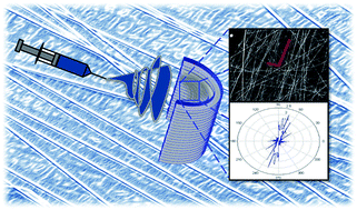
During recent years, electrospinning has become a powerful technique for the cost-effective production of fibrous materials with diameters ranging from a few nanometers up to a few micrometers. In a conventional electrospinning system the produced fibers are collected on a flat grounded collector in a random manner, resulting in isotropic non-woven fibrous mats. Many researchers have been focusing on the modification of the electrospinning collectors for inducing fiber orientation since aligned fibrous mats exhibit unique mechanical, electrical and optical properties rendering them highly attractive in many fields. Unlike other reported collector modification approaches developed for inducing fiber alignment via electrospinning, a very simple concept for producing aligned polymer fibers is presented herein, based on the modification of the electric field profile by replacing the flat metallic collector employed in a typical electrospinning set-up, with a concave one. The electric field profile developed in the case of the flat and the concave collectors was simulated performing a finite elements analysis. Most importantly electrospun meshes were produced and quantification of fiber alignment with a Fourier transform method on different deposition sites of the concave collector showed an up to 70% fiber alignment in the center area. This work creates new prospects towards the design of static collectors employed in electrospinning that could enable the fabrication of highly aligned electrospun fibers.


1. Introduction

Electrospinning is a simple, versatile and cost-effective technique employed in the production of fibrous materials with fiber diameters ranging from a few μm down to a few nm.1–3 Briefly, the electrospinning process involves the application of a high voltage electric field onto a polymer solution or melt, resulting to the induction of electric charges onto the droplet surface generated at the tip of the syringe. At a critical voltage, the electrostatic repulsive forces overcome the solution surface tension, causing the ejection of an electrified liquid jet from the tip that accelerates toward lower-potential regions, i.e. a grounded metallic collector. During this process, the solvent evaporates off resulting to the collection of dry, randomly oriented (nano)fibers onto the grounded collector. Electrospinning can be applied for the generation of fibers composed of not only polymers but also of inorganic materials such as ceramics as well as of composites.4 In most literature examples, fibers are chaotically deposited on a flat, metallic grounded collector in the form of a non-woven mat. However, recent technological advancements requiring the development of well-aligned fibrous materials with ordered structures5 have prompted researchers to search for alternatives for controlling the orientation of electrospun fibers during production. Basically, there are two ways for achieving fiber orientation via electrospinning. The first one involves the manipulation of the electric field between the tip of the spinneret and the collector whereas the second one involves the use of dynamic (rotating) collectors. Mechanical motion translated in most cases to rotary motion employing rotating mandrels6–8 and drums.9–11 as grounded collector platforms have been used to obtain aligned polymer fibers by electrospinning. Electric-field induced fiber orientation has been also realized by introducing among others two separated grounded conductive electrodes as collectors12 whereas this approach has been further expanded by employing an insulating pre-patterned electrode surface as a collector that enabled the generation of more complex aligned fiber arrays.13 In another approach fiber alignment has been realized by using an electrostatic lens element and a collection collector of opposite polarity.14 Moreover, there are examples appearing in the literature combining the two aforementioned strategies i.e. using both, the electric field modification approach and the dynamic collector method in obtaining highly oriented electrospun fibers.15–17 Finally, magnetic-field induced fiber orientation has been also used for obtaining aligned magnetoactive nanofibrous mats.18–21

Herein, a very simple concept is employed for the first time for obtaining aligned fibers via electrospinning. This new approach involves the use of a concave metallic grounded collector instead of a flat one employed in a conventional electrospinning set-up. Compared to the previously reported methodologies developed towards the same purpose, the approach presented herein is easy, straightforward and cost-effective since it does not require the use of mechanical motion, magnetic field or complicated system modification modes for inducing fiber orientation.

Two types of polymer solutions were used in this study in order to investigate the applicability of the concave collector in the alignment of both polymer and polymer-based nanocomposite fibers. More precisely, polyvinylpyrrolidone (PVP) and PVP-capped Pd nanoparticle solutions prepared in methanol were electrospun on flat and on concave collectors. Quantification of the fiber orientation on different locations on the surface of the concave collector was performed by applying a Fourier transform analysis on images obtained by scanning electron microscopy.22,23

In the case of the concave collector, fiber alignment was found to vary depending on the position where the fibers were deposited (center area, left and right) with the highest degree of alignment observed in the center of the collector, reaching up to 70%. The present work creates new prospects in the design of static collectors used in the electrospinning process that could enable the production of highly oriented electrospun nano- and microfibers.

2. Experimental

2.1. Materials and methods

Fig. 1a presents a schematic illustration of the electrospinning set-up employed in the present study. This is essentially the same as the conventional system, with the only difference being the replacement of the flat collector with a concave one. The aluminum concave collector was designed with an inner edge-to-edge diameter of 12.2 cm, internal radius of 7.1 cm and 29.8 cm of height (Fig. 1).
image file: c5ra20429a-f1.tif
Fig. 1 (a) Schematic presentation of the modified electrospinning set-up with a concave collector. (b) Photographs of the concave and flat collectors used as collectors during electrospinning.

PVP (Mn = 1[thin space (1/6-em)]300[thin space (1/6-em)]000 g mol−1, Sigma-Aldrich) fibrous mats were fabricated by electrospinning starting from polymer solutions prepared in methanol (MeOH) (Scharlau). For investigating the applicability of our approach in the alignment of polymer-based electrospun nanocomposite fibers, Pd nanoparticles with average diameters of approximately 5 nm (ref. 24) were introduced in the polymer solution precursor prior to electrospinning. The PVP-capped Pd nanoparticles (mols vinyl pyridine units per mols palladium salt = 9[thin space (1/6-em)]:[thin space (1/6-em)]1) were synthesized according to a previously reported synthetic methodology.25 Briefly, in a round bottom flask equipped with a magnetic stirrer, PVP (1.0 g, 9 mmol of vinylpyrridine units) was dissolved in MeOH (10 mL). Subsequently, palladium(II) acetate (222.2 mg, 1 mmol) was added to the polymer solution and the reaction mixture was heated at reflux (65 °C) for 2 h. During this period, the colour of the solution changed from yellow to dark brown indicating the formation of Pd nanoparticles. After the completion of the reaction, the brown-coloured solution was allowed to cool down to room temperature and it was then stored in a sealed glass vial. The solution was highly stable and no precipitation was observed even after several months.

All electrospinning experiments were performed at room temperature. Equipment included a controlled flow four-channel volumetric microdialysis pump (KD Scientific Model: 789252), a syringe with specially connected spinneret needle electrode, a high-voltage power source (10–50 kV) and custom designed, grounded collector collectors (either flat or concave), inside an interlocked Faraday enclosure safety cabinet.

The electrospinning conditions employed during the experiments were 10% w/v polymer solution concentration, 2 mL h−1 flow (delivery) rate, 16 G needle diameter, 25 cm needle-to-collector distance and 20 kV applied voltage. In order to investigate whether the fiber orientation induced in the presence of the concave collector was retained for long electrospinning periods, the electrospinning time was varied from 1 to 5 minutes.

The morphology of the fibers was investigated by scanning electron microscopy (SEM) (Vega TS5136LS-Tescan). The samples were gold-sputtered (sputtering system K575X Turbo Sputter Coater – Emitech) prior to SEM inspection.

The dependence of the degree of orientation of the fibers on the deposition site was also investigated in the case of the concave collector. More precisely, sample specimens were collected from different positions on the collector i.e. left (L), center-left (CL), center (C), center-right (CR) and right (R) as shown in Fig. 2 to be further analyzed by SEM. Additionally, in order to investigate the effect of the collector geometry on the fiber diameters, the latter were determined from the SEM images using digimizer image analysis software.


image file: c5ra20429a-f2.tif
Fig. 2 Investigation positions for fiber alignment on a concave collector.

Transmission electron microscopy (TEM) analysis was also performed by using a TECNAI F30 G2 S-TWIN microscope operated at 300 kV equipped with energy dispersive X-ray spectrometer (EDX). Samples were placed into a double copper grid (oyster) to be visualized by TEM.

FTIR spectra were recorded using a Shimadzu FTIR-NIR Prestige-21 spectrometer bearing an ATR accessory.

Thermal gravimetric analysis (TGA) measurements were performed on a Q500 TA Instruments under nitrogen flow at a heating rate of 10 °C min−1.

Mechanical testing was performed using a high precision mechanical testing system (Instron 5944, Norwood, MA, USA). The specimens were cut in an orthogonal shape with dimensions 12 × 8 × 1 mm (length × width × thickness) and placed between two parallel grips. Tensile stress–strain experiments were carried out to study the elastic response of the material. The specimens were stretched to 30% strain with a strain rate of 0.5 mm min−1. The stress was calculated as the force measured on the load cell divided by the initial area of the specimen (i.e., 1st Piola-Kirchhoff stress) and the strain was calculated as the displacement, Δl divided by the initial length of the specimen. The Young's modulus was calculated from the slope of the linear part of the stress–strain curves for low strains. Six specimens were tested for each group (n = 6).

2.2. Finite element analysis of the electric field profile

Since the electrospinning process highly depends on the electric field the finite element based software package COMSOL Multiphysics® (Burlington, MA) was used in order to study the electrostatic configuration of our set-up. This was done for both flat and concave collectors using the dimensions shown in Fig. 1 and with a needle voltage compatible with that of the set-up. We are primarily interested in a qualitative comparison between the electric fields of flat and concave collectors and for this reason a two-dimensional model was sufficient.

2.3. Calculation of 2D fiber orientation tensor

The methodology described by Sander and Barocas in ref. 22 was employed to calculate an averaged 2D orientation tensor from the SEM images using the Fourier transform method (FTM). The fiber orientation tensor is defined as
image file: c5ra20429a-t1.tif
where li is the length of the i-th fiber, ltot is the total fiber length, and the sum is over all fibers. θ is the angle formed between the fiber and the x-axis. The sum of the diagonal components is always one. For isotropic networks, Ωxx = Ωyy = 0.5, while for networks with a preferred alignment, the diagonal component of the orientation tensor that corresponds to the preferred direction is greater than the other.

3. Results and discussion

Initial studies involved the investigation of the electric field profile existing between the tip of the spinneret and the two types of metallic collectors. The results are summarized in Fig. 3, where the effect of introducing a curvature on the collector is illustrated. Near the surface of the flat collector the electric field is homogeneous (neglecting the edges) (Fig. 3a). In contrast the introduction of a concave collector results in inhomogeneous electric field, particularly within the collector's cavity (Fig. 3b). Based on previously reported studies, a slight variation in the electric field profile (i.e. electric field inhomogeneity) may induce fiber orientation.5
image file: c5ra20429a-f3.tif
Fig. 3 The electrostatic configuration of the electrospinning set-up, obtained from a finite-element model. The electric field vectors and equipotential lines are displayed (a) the configuration for a flat collector (b) the configuration for a concave collector. The color legend indicates the value of the electric potential.

For the experimental verification of the aforementioned, electrospinning of both PVP and PVP/Pd solutions was carried out under identical electrospinning conditions with the only difference being the geometry of the metallic collector. Upon introducing the conventional flat metallic fiber collector, randomly oriented PVP fibers were generated which were uniformly distributed on the collector's surface. The same behavior was also observed in the case of the nanocomposite PVP/Pd system, indicating that the presence of the Pd NPs within the polymer solution had no effect on the fiber orientation. Fig. 4a provides a photograph of the PVP/Pd fibers that were randomly deposited on the flat collector. PVP/Pd fiber alignment was observed along the concave collector as seen in the photograph provided in Fig. 4b. The brown color of the fibers is attributed to the presence of the Pd nanoparticles embedded within the fibers.24


image file: c5ra20429a-f4.tif
Fig. 4 Photographs of the PVP/Pd electrospun nanocomposite fibers deposited on the flat (a) and concave (b) metallic collectors.

The obtained fibers were characterized in terms of their thermal stability, composition and morphology by thermal gravimetric analysis (TGA), FTIR and electron microscopy (SEM, TEM) respectively.

The decomposition temperatures of the pristine PVP and the PVP/Pd electrospun fibers were determined by TGA. As seen from the thermograms provided in Fig. 5, PVP degrades at approximately ∼460 °C in line with previously reported findings. The remaining residue observed in the case of the Pd-containing fibers at T > 500 °C, corresponds to the metallic palladium content.


image file: c5ra20429a-f5.tif
Fig. 5 TGA thermograms of PVP and PVP/Pd fibrous mats.

FTIR analysis was performed to obtain information on the chemical composition of the fibrous mats. Fig. 6 illustrates the FTIR spectra of the PVP and the PVP/Pd nanocomposite fibrous mats. Both spectra show a strong band at ∼1660 cm−1 characteristic of the stretching vibration of the C[double bond, length as m-dash]O group that is present in PVP. This band is shifted to slightly lower wavenumber in the PVP/Pd nanocomposite whereas it also exhibited a decrease in the width. According to C. Evangelisti et al.26 the broadness of the carbonyl stretching vibration band in PVP decreases in the presence of Pd due to the development of PVP/Pd intermolecular interactions in which the C[double bond, length as m-dash]O group is involved, acting competitively to the PVP–PVP intermolecular interactions.


image file: c5ra20429a-f6.tif
Fig. 6 FTIR spectra of PVP and PVP/Pd fibrous mats.

Fig. 7 provides indicative SEM images of the PVP and PVP/Pd electrospun fibers deposited on the flat metallic collector.


image file: c5ra20429a-f7.tif
Fig. 7 SEM images of the PVP (a and b) and the PVP/Pd (c and d) fibers deposited on the flat metallic collector. Deposition time: (a) and (c): 1 minute; (b) and (d): 3 minutes. Scale bar: 100 μm.

The PVP/Pd nanocomposite fibers were also visualized by TEM (Fig. 8). The TEM bright field images reveal that the Pd nanoparticles are homogeneously distributed within the fibers and they are spherical in shape with average diameters of around 5 nm.24 Moreover, as seen in the HRTEM image (Fig. 8, right image) the Pd nanoparticles are nanocrystals disclosing the crystalline planes (111) and (200) with characteristic interplanar distances of 2.27 and 1.97 Å respectively.


image file: c5ra20429a-f8.tif
Fig. 8 TEM bright field and HRTEM images of the PVP/Pd nanocomposite electrospun fibers.

The morphologies and orientations of the PVP and PVP/Pd electrospun fibers deposited at different sites (L, CL, C, CR, R) on the concave collector were investigated by SEM. Most importantly, the degree of fiber orientation was quantified using FTM. In the results, Fig. 9 and 10, the vectors on the SEM images show the direction and relative degree of orientation of the fibers. For isotropic fiber networks that have no preferred orientation the direction of the vectors is random and their length is equal. For anisotropic fiber networks the longer vector points towards the direction of the preferred alignment. The figures also present the analysis of the FTM that shows the distribution of the angles θ, as well as the components of the fiber orientation tensor Ω. As shown in the figures, when a flat collector was used the resulting electrospun fiber networks (both PVP and PVP/Pd) had a random orientation with the diagonal components of the orientation tensor to be almost equal to each other (Fig. 9). Upon replacing the flat collector with the concave one, the fibers deposited on the sides of the concave collector (positions L and R) still had a random orientation (Fig. 10b and d). However, at the centre of the collector the fibers exhibited a high degree of alignment of approximately 0.6 to 0.7 for both the PVP and PVP/Pd electrospun fibers (Fig. 10a and c).


image file: c5ra20429a-f9.tif
Fig. 9 SEM images and vectors showing the direction and relative degree of orientation of the PVP and PVP/Pd fibers deposited on a flat collector (left image). FTM analysis showing the angle θ distribution (right image) and the components of the fiber orientation tensor Ω.

image file: c5ra20429a-f10.tif
Fig. 10 SEM images and vectors showing the direction and relative degree of orientation of the PVP and PVP/Pd fibers deposited on the concave collector on different sites (left image). FTM analysis showing the angle θ distribution (right image) and the components of the fiber orientation tensor Ω. (a) PVP on concave – center area (b) PVP on concave – left and right areas (c) PVP/Pd on concave – center area (d) PVP/Pd on concave – left and right areas.

Table 1 summarizes the degree of orientation of the fibers deposited on the concave and on the flat collector, as determined from the SEM images, by employing a Fourier transform method (FTM).

Table 1 Degree of orientation of the fibers deposited on different locations on the concave collector in comparison to the flat collector
  Concave collector Flat collector
Center (C) Center-left (CL) Center-right (CR) Left/right (L, R) Center area
PVP 70% 68% 60% Random orientation Random orientation
PVP/Pd 68% 70% 70% Random orientation Random orientation


Besides processing parameters including electrical potential, solution flow rate, needle diameter, and needle-to-collector distance, the electric field distribution may have an influence on the fiber diameters. As previously noted, the concave geometry induces an electric field inhomogeneity which is more pronounced at the collector's center area. This phenomenon not only induces fiber orientation but also results in the reduction of the fiber diameters in comparison to the ones deposited on the flat collector at the center area, as seen from the data provided in Table 2.

Table 2 Average diameters and standard deviations of the electrospun PVP and PVP/Pd fibers deposited on the flat and concave static collectors
  Concave collector Flat collector
Center area Left/right area Center area
PVP 0.58 ± 0.11 μm 0.88 ± 0.18 μm 0.85 ± 0.12 μm
PVP/Pd 0.74 ± 0.19 μm 1.06 ± 0.15 μm 1.02 ± 0.29 μm


Basic statistical analysis of the experimental data (t-test) demonstrated that the differences observed in the diameters of the fibers when comparing PVP and PVP/Pd deposited on the flat and the concave collector (center area) are statistically significant (p < 0.05).

In line with the above, C. J. Angammana and S. H. Jayaram have studied the electric field profile in the multi-jet electrospinning process and its influence on the fiber morphology. Using COMSOL Multiphysics, they have calculated the electrostatic-field distribution between the needle and the collector, in order to obtain the results for single and multi-jet arrangements. From their studies they found that the diameter of the fibers decreased with the increase in the number of needles in the arrangement due to the increase of the electric field's distortion and the deterioration of the local electric field.27

Considering the electric field profile differences observed between the flat and the concave collector geometry, the above results experimentally verified that the electric field inhomogeneity which was more pronounced within the collector's central cavity, promoted fiber orientation to a relatively high extent for both systems whereas it also led to a decrease in the diameters of the fibers.

Based on previous literature reports, both the fiber diameter and the fiber orientation are influencing factors on the mechanical properties of the fibers.28–30 In order to verify this experimentally, we have studied the mechanical properties of both, the PVP and the PVP/Pd fibrous mats deposited in the center areas of the flat and concave collectors.

The experimentally obtained stress–strain curves are illustrated in Fig. 11a. The random PVP and PVP/Pd meshes generated using the flat target exhibited a similar mechanical response and both meshes became stiffer for the concave target, when they were stretched in the direction of the preferred alignment. Additional the meshes with the preferred alignment reached a yield point at 20–25% strain, while the stress developed in the random networks reached a plateau at these strain levels. The Young's moduli depicted in Fig. 11b, were calculated from the slope of the linear part of the stress–strain curves for low strains (<10%).


image file: c5ra20429a-f11.tif
Fig. 11 Stress–strain curves (a) and corresponding Young's moduli (b) for the PVP and PVP/Pd meshes generated using the flat and the concave collector. The asterisk denotes a statistically significant difference (p < 0.05).

4. Conclusions

A simple collector design concept has been employed for the first time in electrospinning for inducing fiber orientation, involving the replacement of the conventional static flat collector to a concave one. The presented approach is considered to be advantageous in comparison to already existing concepts employed for the fabrication of aligned electrospun fibers, due to its cost-effectiveness and the avoidance of mechanical motion, magnetic field or more complicated system modification modes for inducing fiber orientation. Quantification of the fiber orientation on different locations on the surface of the concave collector could be realized by applying a Fourier transform analysis on images obtained by scanning electron microscopy. The obtained results demonstrated that the concave collector approach led to the generation of pristine polymer and organic–inorganic polymer-based nanocomposite fibers with a relatively high degree of alignment reaching up to 70% in the center area of the collector and enhanced mechanical properties. Thus, based on this study, new prospects are created on the design and construction of new static collectors that could enable the facile and cost-effective production of highly oriented electrospun fibers.

Acknowledgments

This work was supported by the MNT-ERA.NET Carpolcap project through the Cyprus Research Promotion Foundation (Grant No. KOINA/MNT-ERA.NET/0311/01) and the University of Cyprus Grant “Post-doctoral Researchers” supporting Dr I. Savva. We are grateful to Dr Eugenia Vasile (University Politehnica of Bucharest) for the TEM measurements and to Dr Panayiotis Koutentis (University of Cyprus, Department of Chemistry) for providing access to the TGA apparatus.

References

  1. J. Doshi and D. H. Reneker, J. Electrost., 1995, 35, 151 CrossRef CAS.
  2. D. H. Reneker and I. Chun, Nanotechnology, 1996, 7, 216 CrossRef CAS.
  3. T. Subbiah, G. S. Bhat, R. W. Tock, S. Parameswaran and S. S. Ramkumar, J. Appl. Polym. Sci., 2005, 96, 557 CrossRef CAS.
  4. Z.-M. Huang, Y.-Z. Zhang, M. Kotaki and S. Ramakrishna, Compos. Sci. Technol., 2003, 63, 2223 CrossRef CAS.
  5. W. E. Teo and S. Ramakrishna, Nanotechnology, 2006, 17, R89–R106 CrossRef CAS PubMed.
  6. M. Putti, M. Simonet, R. Solberg and W. M. P. Gerrit, Polymer, 2015, 63, 189 CrossRef CAS.
  7. A. Subramanian, U. M. Krishnan and S. Sethuraman, Biomed. Mater., 2011, 025004 CrossRef PubMed.
  8. C. Ayres, G. L. Bowlin, S. C. Henderson, L. Taylor, J. Shultz, J. Alexander, T. Telemeco and D. G. Simpson, Biomaterials, 2006, 27, 5524 CrossRef CAS PubMed.
  9. M. D. R. Kok and J. T. Gostick, J. Membr. Sci., 2015, 473, 237 CrossRef CAS.
  10. X. He, Q. Xiao, C. Lu, Y. Wang, X. Zhang, J. Zhao, W. Zhang, X. Zhang and Y. Deng, Biomacromolecules, 2014, 15, 618 CrossRef CAS PubMed.
  11. G. Wang, Z. Tan, X. Liu, S. Chawda, J.-S. Koo, V. Samuilov and M. Dudley, Nanotechnology, 2006, 17, 5829 CrossRef CAS.
  12. D. Li, Y. Wang and Y. Xia, Nano Lett., 2003, 3, 1167 CrossRef CAS.
  13. D. Li, Y. Wang and Y. Xia, Adv. Mater., 2004, 16, 361 CrossRef CAS.
  14. J. M. Deitzel, J. D. Kleinmeyer, J. K. Hirvonen and N. C. B. Tan, Polymer, 2001, 42, 8163 CrossRef CAS.
  15. Q. Zhang, Z. Chang, M. Zhu, X. Mo and D. Chen, Nanotechnology, 2007, 18, 115611 CrossRef.
  16. W. E. Teo, M. Kotaki, X. M. Mo and S. Ramakrishna, Nanotechnology, 2005, 16, 918 CrossRef CAS.
  17. A. Theron, E. Zussman and A. L. Yarin, Nanotechnology, 2001, 12, 384 CrossRef.
  18. L. Y. Mei, P. Song and Y. Q. Liu, J. Appl. Polym. Sci., 2015, 132, 41995 CrossRef.
  19. Y. Liu, X. Zhang, Y. Xia and H. Yang, Adv. Mater., 2010, 22, 2454 CrossRef CAS PubMed.
  20. D. Yang, J. Zhang, J. Zhang and J. Nie, J. Appl. Polym. Sci., 2008, 110, 3368 CrossRef CAS.
  21. D. Yang, B. Lu, Y. Zhao and X. Jiang, Adv. Mater., 2007, 21, 3702 CrossRef.
  22. E. A. Sander and V. H. Barocas, J. Biomed. Mater. Res., Part A, 2009, 88, 322 CrossRef CAS PubMed.
  23. T. Stylianopoulos, M. Kokonou, S. Michael, A. Tryfonos, C. Rebholz, A. D. Odysseos and C. Doumanidis, J. Biomed. Mater. Res., Part B, 2012, 100, 2222 CrossRef PubMed.
  24. I. Savva, A. S. Kalogirou, A. Chatzinicolaou, P. Papaphilippou, A. Pantelidou, E. Vasile, E. Vasile, P. A. Koutentis and T. Krasia-Christoforou, RSC Adv., 2014, 4, 44911 RSC.
  25. J. S. Bradley, E. W. Hill, S. Behal, C. Klein, A. Duteil and B. Chaudret, Chem. Mater., 1992, 4, 1234 CrossRef CAS.
  26. C. Evangelisti, N. Panziera, A. D'Alessio, L. Bertinetti, M. Botavina and G. Vitulli, J. Catal., 2010, 272, 246 CrossRef CAS.
  27. C. J. Angammana and S. H. Jayaram, IEEE Trans. Ind. Appl., 2011, 47, 1028 CrossRef.
  28. T. Amornsakchai, D. L. M. Cansfield, S. A. Jawad, G. Pollard and I. M. Ward, J. Mater. Sci., 1993, 28, 1689–1698 CrossRef CAS.
  29. A. Baji, Y.-W. Mai, S.-C. Wong, M. Abtahi and P. Chen, Compos. Sci. Technol., 2010, 70, 703 CrossRef CAS.
  30. G. Mathew, J. P. Hong, J. M. Rhee, D. J. Leo and C. Nah, J. Appl. Polym. Sci., 2006, 101, 2017 CrossRef CAS.

Footnote

Equal contribution.

This journal is © The Royal Society of Chemistry 2015
Click here to see how this site uses Cookies. View our privacy policy here.