Fe/N co-doped carbon microspheres as a high performance electrocatalyst for the oxygen reduction reaction

Pengpeng Cheng , Shuoshuo Li, Ruchun Li, Jing Yan, Wendan Yu, Xiaofeng Shao, Zhaoxia Hu and Dingsheng Yuan*
Department of Chemistry, Jinan University, Guangzhou 510632, PR China. E-mail: tydsh@jnu.edu.cn; Fax: +86 20 8522 1697

Received 23rd September 2015 , Accepted 2nd December 2015

First published on 3rd December 2015


Abstract

Recently, nitrogen-doped carbon materials have attracted immense interest because of their great potential in various applications. In this work, FeN-doped carbon microspheres are large-scale synthesized using basic magnesium carbonate as the template and glycine as the carbon and nitrogen precursor by a simple liquid impregnation method under a relatively low pyrolysis temperature. Iron is introduced into the carbon microspheres to enhance the graphitic degree and improve the electrocatalytic performance. This carbon material with high specific area, high nitrogen content and part-graphitization shows high activity and four-electron selectivity for the oxygen reduction reaction in an alkaline medium. Compared to a commercial Pt/C catalyst, this material presents exceeding stability and durability, which can be a candidate for potential applications in the fuel cell and electrochemical industries of oxygen reduction.

1. Introduction

In recent years, proton electrolyte membrane fuel cells (PEMFCs) and direct methanol fuel cells (DMFCs) have been recognized as environmentally friendly and highly efficient electric generating devices.1–5 The oxygen reduction reaction (ORR) at the cathode is an important process in PEMFCs because the cathodic activation and reduction of oxygen were much more difficult than the anodic activation and oxidation of hydrogen.6 Therefore, platinum catalyst must be used on the cathode to accelerate the ORR. However, the price was one of the main obstacles, which was directly related with the widely used high cost Pt based catalyst. On the other hand, Pt based catalysts were easily poisoned and thus limited their large-scale commercial applications.7–9 Therefore, the search for cheap, stable and more active electrocatalysts for ORR was of great importance.

According to recent intense research efforts in reducing or replacing Pt based catalysts in fuel cells, N-doped carbon nano-materials were shown high catalytic activity and cycle stability for ORR, suggesting the N-doped carbon materials as metal-free catalysts to replace Pt had a potential application prospect in the field of electrochemical energy storage and conversion.4,10–14 In general, the synthesis methods for nitrogen-doped carbon materials were post synthesis modification,15,16 chemical vapor deposition17,18 and pyrolysis19,20 and so on. A lot of carbon materials had been reported by using silica,21–23 polystyrene sphere,24,25 and metal oxide26,27 as templates. Sevilla et al. had prepared graphitic porous carbons with a wide variety of textural properties by using a silica xerogel as template and a phenolic resin as carbon precursor.23 In our previous work, we had prepared graphitic ordered mesoporous carbon for the first time using mesoporous nickel oxide as a template and catalyst and dopamine as a carbon source.27 Among them, using various kinds of templates to synthesize spherical carbon materials had been widely used due to their easy synthesis and industrial feasibility.28

Basic magnesium carbonate (xMgCO3·yMg(OH)2·zH2O) was considered as one of the most important compounds of the magnesium industry, which was widely used in toothpaste, cosmetic, plastic, retardant and rubber as additive.29,30 Recently, considerable attention had been paid to the preparation of basic magnesium carbonate with various morphologies. For example, Ohkubo et al.31 had synthesized petaloid microspheres of basic magnesium carbonate with a primary particle size of several micrometers under ultrasonic irradiation using magnesium sulfate and sodium carbonate as starting materials. A porous Mg5(CO3)4(OH)2·4H2O spheres with rosette-like morphologies had been prepared by reacting anhydrous magnesium sulfate and urea via a hydrothermal method.32 The different morphologies were obtained when synthetic methods were changed, but all of them were almost composed of nanosheet structures and possess a relatively high specific surface area. Furthermore, high purity of basic magnesium carbonate was non-toxic, which was harmless to our bodies, suggesting basic magnesium carbonate could be used ashe template for the preparation of porous carbon materials.

Herein, large-scale FeN- and N-doped carbon microspheres (NCMS-Fe and NCMS) with high specific surface area were successfully prepared using basic magnesium carbonate (Mg5(CO3)4(OH)2·4H2O) as the template and glycine as carbon and nitrogen precursor. Iron was introduced into NCMS to improve the graphitic degree and enhance the electrocatalytic performance. The NCMS-Fe was used as ORR electrocatalyst with direct four electron process and exhibited excellent activity and stability in alkaline medium.

2. Experimental section

2.1. Synthesis of Mg5(CO3)4(OH)2·4H2O microspheres

The hard template Mg5(CO3)4(OH)2·4H2O was synthesized according to the previous reports with slight modifications.33,34 Typically, 0.04 mol MgCl2 was dissolved in 200 mL deionized water to form a transparent solution, which was then heated to 80 °C at the water bath. Meanwhile, 200 mL Na2CO3 solution with the same concentration was heated to the same temperature as the MgCl2 solution and rapidly added into the vigorously stirred MgCl2 solution. The mixture was further stirred for 90 s and then maintained at the same temperature for 1 h. Finally, a white precipitate was collected, filtered off, and washed with deionized water and ethanol several times. The Mg5(CO3)4(OH)2·4H2O was obtained after dried at 60 °C for 3 h.

2.2. Preparation of NCMS

1 g Mg5(CO3)4(OH)2·4H2O was added into a 50 mL beaker containing solution of 30 mL water and 1 g glycine. After vigorously stirring for an hour, the beaker was sealed by taut Saran Wrap and put into the oven at 100 °C for 6 h. The as-prepared dry materials were carbonized under nitrogen flow at 900 °C for 2 h with a heating rate of 2 °C min−1 and a cooling rate of 5 °C min−1 to room temperature. Followed by treatment with 3 mol L−1 HCl solution for 12 h, the N-doped carbon microspheres denoted as NCMS was obtained after the removal of the impurities. For improving the graphitization degree, the whole process was followed as above-mentioned but 20 mL 0.1 mmol L−1 Fe(NO3)3 solution was added with the template at the same time, and then the product was labeled as NCMS-Fe.

2.3. Characterization

The samples were characterized by a MSAL-XD2 X-ray diffractometer (XRD, Cu Kα, 40 kV, 20 mA, λ = 1.5406 Å). The morphologies were examined by field emission scanning electron microscope (FESEM, ZEISS Ultra 55) and JEM2010 high-resolution transmission electron microscopy (HRTEM) operating at 200 kV. The X-ray photoelectronic spectroscopy (XPS) was carried out using an ESCALab250 spectrometer with Alumina Kα (1486.6 eV) source. Nitrogen sorption isotherms of as-prepared materials were studied by a Micromertics TriStar 3000 analyzer at 77 K. The plot of specific surface area was deduced from the isotherm analysis of adsorption data at the relative pressure (P/P0) of 0–1.0 and the average pore diameters were collected from the peak value on the pore diameter distribution. The degree of crystalline structure of as-prepared samples were investigated by a Raman spectroscopy, which was recorded in a backscattering configuration using the 514.5 nm line of an Ar+ ion laser and a Renishaw in Via Plus Raman spectrometer.

2.4. Electrochemical characterization

The electrochemical measurements were carried out on a CHI660D electrochemical workstation (CH Instruments, China) at 25 °C in a conventional three-electrode system. Platinum foil (1.0 × 1.0 cm2) and Ag/AgCl (saturated KCl) were used as counter electrode and reference electrode, respectively. A rotating ring disk electrode (RRDE) system (Pine Instrument Co., Grove City, PA) and rotating disk electrode (RDE) system were used as working electrode, the glassy carbon electrode (5 mm diameter) was polished before each experiment with 1, 0.3 and 0.05 μm alumina powder, respectively, and then washed in a mixture of ethanol with water before each experiment. The ORR activity of NCMS was evaluated in 0.1 mol L−1 KOH solution and recorded with the potentiostat at a scan rate of 10 mV s−1. To make KOH solution oxygen or nitrogen saturated, pure O2 or pure N2 gas was bubbled directly into the solution for at least 30 min before measurements and was flushed over the cell solution during the tests.

All the working electrodes for cyclic voltammetries (CVs) and chronoamperometric (it) responses were prepared with the same procedure as follows: 2 mg catalyst was mixed 100 μL Nafion (5 wt%) with 1.0 mL ethyl alcohol. The mixture was sonicated for 30 min, and 10 μL of the dispersion was deposited on the glassy carbon electrode and dried under ambient conditions to obtain a catalyst thin film. The catalyst loading is about 0.092 mg cm−2.

3. Results and discussion

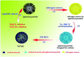
The NCMS was designed to be nitrogen-doped carbon microspheres according to the preparation procedure, as shown in Fig. 1. Typically, MgCl2 solution was rapidly mixed with Na2CO3 solution under vigorously stirring, and the flocculent amorphous precipitate was appeared, which was then changed to the needlelike magnesium carbonate crystal (MgCO3·3H2O) during the aging process at low temperature. When the temperature was higher than 55 °C, the needlelike MgCO3·3H2O was transferred into the layer-like structure of Mg5(CO3)4(OH)2·4H2O spherical particle.33 Under controlled reaction conditions the layer-like structure of Mg5(CO3)4(OH)2·4H2O spherical particle as the template was filled with glycine. The glycine was carbonized at high temperature under the flowing N2, forming a carbon layer. Meanwhile, the nitrogen element in the precursor was left in the carbon layer which was mesoporous with lots of breach, followed by treatment with 3 mol L−1 HCl solution to removal the Mg5(CO3)4(OH)2·4H2O template, the nitrogen-doped carbon microspheres (NCMS) with porous structure was obtained. The same synthesis procedures were used to prepare the porous NCMS-Fe. The spherical porous structure would provide much more active sites which were expected to be dispersed uniformly on the carbon spheres, making the best use of the active elements and leading to high performance.
image file: c5ra19620e-f1.tif
Fig. 1 Schematic diagram for the formation process of NCMS.

The wide-angle powder XRD pattern of Mg5(CO3)4(OH)2·4H2O was shown in Fig. 2a, all the sharp and strong diffraction peaks were corresponded to the typical characteristic peaks of Mg5(CO3)4(OH)2·4H2O (JCPDS no. 25-513). Several strong diffraction peaks of NCMS and NCMS-Fe without acid treatment in Fig. 2b were corresponded to the standard diffraction peaks of MgO formed after annealing Mg5(CO3)4(OH)2·4H2O. As shown in Fig. 2c, two diffraction peaks appeared at 26° and 43°, corresponding to the (002) and (100) planes of graphite. However, all peaks of the NCMS were broad and weak, indicating that the material was low graphitization. Compared with the NCMS-Fe, the (002) diffraction peak of NCMS-Fe was much more sharp and narrow. In addition, the diffraction peak with very close at 43° which can be assigned to the (100) and (101) planes, indicating NCMS-Fe possessed a higher graphitization degree than NCMS which can be evaluated by Raman spectrum in Fig. 2d. Both NCMS and NCMS-Fe showed two obvious peaks of D band (∼1346 cm−1) and G band (∼1594 cm−1) as well as a weak peak 2D band (∼2889 cm−1). The IG/ID value of NCMS-Fe (1.198) was higher than NCMS (1.098), indicating that the NCMS-Fe had higher graphitic crystalline structure. Moreover, carbon materials with special graphitization structure and crystal orientation would show better stability and higher corrosion resistance in the electrocatalytic process.27


image file: c5ra19620e-f2.tif
Fig. 2 XRD patterns of (a) Mg5(CO3)4(OH)2·4H2O and (b) NCMS and NCMS-Fe without the treatment of acid and (c) after the treatment of acid, (d) Raman spectra of NCMS and NCMS-Fe.

The morphologies of the samples were characterized by SEM and TEM. Fig. 3a and b showed the SEM images of Mg5(CO3)4(OH)2·4H2O, clearly observing the template spheres with regular shape and uniform sizes have been successfully synthesized. Fig. 3c and d showed the SEM images of NCMS and NCMS-Fe which used glycine as carbon resources. It can be seen that the carbon materials after acid treatment were getting a little out of shape, which may attribute to the partial collapse after removing the template. However, most of the carbon spheres remained the spherical frame and layer structure. Additionally, we also can observe that the layer structures of the carbon spheres were quite distinct from the templates, the layer structure of the template was much smoother than the carbon spheres which contained various pore structures. The possible reason was that Mg5(CO3)4(OH)2·4H2O was decomposed at high temperature32 and the CO2 and water steam escaped from the surface of the carbon materials and formed pore structure on the surface. The porous structure was not only benefit for increasing the specific surface area of the carbon material, but also was advantageous to the electrolyte to diffuse into the material to make the electrons that can quickly transfer between the active sites on the surface of the catalyst and reactant and obtain quick kinetic response in electrocatalysis. Note that large-scale NCMS and NCMS-Fe could be successfully synthesized using a large number of sphere templates.


image file: c5ra19620e-f3.tif
Fig. 3 SEM images of (a and b) Mg5(CO3)4(OH)2·4H2O, (c) NCMS and (d) NCMS-Fe.

The more detailed structure characteristics of the NCMS and NCMS-Fe were shown in the HRTEM images (Fig. 4). From Fig. 4a and c, it can be seen that the local position of NCMS and NCMS-Fe was appeared some lattice fringes which may ascribe to the result of amorphous carbon transformed into graphitized carbon. We can clearly observe that the lattice fringes of NCMS-Fe were more than NCMS, implying NCMS-Fe possess higher graphitization degree than NCMS which was in good agreement with the XRD diffraction pattern and SAED pattern (Fig. 4b and d).


image file: c5ra19620e-f4.tif
Fig. 4 HRTEM images of NCMS (a and b) and NCMS-Fe (c and d).

Nitrogen adsorption–desorption isotherms and the pore size distribution of Mg5(CO3)4(OH)2·4H2O, NCMS and NCMS-Fe were shown in Fig. 5. Mg5(CO3)4(OH)2·4H2O was abundant with macropores, which is proven by the pseudo-type I isotherm with H1 hysteresis loop at high relative pressure (see Fig. 5a). The adsorption of micropores took place at low relative pressure where the adsorption isotherm of the sample became rapidly saturated. The platform at P/P0 = 0.20–0.80 originated from the outer surface adsorption of the sphere. In addition, there was a clear increase from a relative pressure of 0.8 in the adsorption branch of the sample and a hysteresis loop at P/P0 = 0.80–0.99 with a pronounced desorption step, demonstrating macroporous adsorption of the layer gap. The BET surface area of Mg5(CO3)4(OH)2·4H2O were only 38 m2 g−1 implying macroporous contribution. The isotherms of NCMS (Fig. 5b) and NCMS-Fe (Fig. 5c) with a hysteresis loop near relative pressure of 0.45 in the desorption branches illustrated the presence of mesopores. The following sharp increase in the adsorption curves at high relative pressure of 0.97 was observed, resulting from the multilayer adsorption of nitrogen in macropores formed among the carbon spheres, where these macropores are also seen from the above-mentioned SEM images. The BET surface area of NCMS and NCMS-Fe were 578 and 623 m2 g−1, respectively.


image file: c5ra19620e-f5.tif
Fig. 5 N2 adsorption–desorption isotherms and pore size distributions of Mg5(CO3)4(OH)2·4H2O (a), NCMS (b) and NCMS-Fe (c).

The X-ray photoelectron spectroscopy (XPS) was used to identify the chemical states and the contents of the C, N and O elements. Fig. 6a showed the XPS survey spectra of the NCMS and NCMS-Fe which reveal the presence of C1s, N1s and O1s peaks, indicating that nitrogen is in situ doped into the carbon materials. However, in addition to the above three absorption peaks, the peak at the binding energy of 710 eV was attributed to the Fe2p, indicating that the NCMS-Fe has traces of iron which may improve the electrical activity of catalyst.35 Detailed analysis of C1s and N1s peaks were shown in Fig. 6b and c. The overlapped C1s peaks were decomposed into four components arising from C–C (284.7 eV), C–N (285.5 eV), C–O (286.3 eV) and C[double bond, length as m-dash]O (287.2 eV). Four types of nitrogen were recognized from N1s spectrum in Fig. 6c which were located at 398.5 eV, 400.0 eV, 401.3 eV and 403.1 eV, corresponding to the pyridinic-N (N-6), pyrrolic-N (N-5), quaternary-N (N-Q) and pyridinic-N-oxide (N-oxide) groups.


image file: c5ra19620e-f6.tif
Fig. 6 (a) XPS survey spectra, high-resolution XPS spectra of C1s (b) and N1s (c) of the NCMS and NCMS-Fe.

The total nitrogen contents of NCMS and NCMS-Fe were calculated from XPS to be 7.36 and 5.62 wt%. Detailed nitrogen contents of NCMS and NCMS-Fe were shown in Table 1. The content of the pyridinic-N in NCMS-Fe was 38.86 wt%, which was higher than NCMS (37.80 wt%). It was commonly accepted that the ORR activity of nitrogen-doped carbon came from the pyridinic-N.36–38 Previous literature reports39–41 also suggested the enhanced ORR activity in the CNx catalysts containing pyridinic-type nitrogen functionalities which may ascribed to the conjugation effect of the nitrogen lone pair electrons on the nitrogen and graphene π-system. More recently, Keith J. Stevenson and co-workers reported the increase in bulk electrical conductivity, work function, and the density of states at the Fermi level with the increased nitrogen doping in CNTs. This may stem from the existence of an electron-rich nitrogen site, for example, pyridinic nitrogen, which possesses a lone pair of electrons in addition to an electron donated to the conjugated π-bond system (mixed σ–π valence states). It was also reported that nitrogen doping in carbon nanotubes will result in chemically active, localized areas of higher electron density and promotes the electrocatalysis of ORR in aqueous electrolytes.42 Furthermore, the existence of iron (0.53 wt%) also may play a crucial role for the enhanced activity of the ORR.35,43 Therefore, we predicted that the NCMS-Fe have better performance in ORR than NCMS.

Table 1 Contents of different N-containing functional groups in the NCMS and NCMS-Fe obtained by the deconvolution of the N1s spectra
Sample N-6 (%) N-5 (%) N-Q (%) N-O (%)
NCMS 37.80 35.70 19.73 6.77
NCMS-Fe 38.86 22.38 31.70 7.06


The activities of the samples for oxygen electro-reduction in O2-saturated 0.1 mol L−1 KOH electrolyte were evaluated by rotating disk electrode (RDE), as shown in Fig. S1. The comparable electrocatalytic activities of NCMS, NCMS-Fe and 20% Pt/C for ORR were shown in Fig. S1a. NCMS-Fe was visibly better than NCMS which exhibited the positively shifted onset potentials as well as the increase of limit current density, close to that of commercial Pt/C. This indicated that the increase in ORR activity is most closely correlated to the pyridinic-type nitrogen functionality. The existence of more pyridinic functionalities in the NCMS-Fe may be one of the reasons for facilitating reductive O2 adsorption at open-circuit conditions, which is in accordance with available literature data. In addition, we had originally tried to remove Fe from the samples so that they were continuously washed by acid treatment. It was so surprised that the iron still existed in NCMS-Fe by XPS spectra confirmation, implying that FeNC is very stable. According to the literature report,43 the iron played a decisive role in Fe/N/C catalysts for ORR and the N–Fe bonds form different coordinated structures in the electrocatalysts could be determinant for the activity and onset potential.

To further assess the ORR catalytic activity and kinetics of NCMS-Fe and 20% Pt/C, the comparable electrocatalytic activities of NCMS-Fe and 20% Pt/C for ORR measured by rotating ring disk electrode (RRDE) were shown in Fig. 7. The ORR polarization curve within the potential range from 0.2 V to −0.8 V have shown in Fig. 7a. With the increase of electrode rotation rate, the limit disk current densities of ORR at NCMS-Fe modified electrode oxygen reduction reaction were all increasing as well as the limit ring current densities. For comparison, NCMS-Fe and commercial 20% Pt/C were tested by RRDE in 0.1 M KOH under the rotation rate of 1600 rpm (Fig. 7b). The onset potential of NCMS-Fe was 0.003 V which was closed to Pt/C (0.035 V), while the half-wave potential difference is only ∼5 mV. In addition, compared with some other recent reported ORR catalysts in Table S1, the lower onset potential of the NCMS-Fe indicated a better performance toward ORR. Fig. 7c showed the peroxide yield and electron transfer number which can be analyzed from RRDE data (Fig. 7b) by the followed equations:

 
H2O2 (%) = 200 × Ir/(Ir + NId) (1)
 
n = 4 × Id/(Ir/N + Id) (2)
where Id is disk current, Ir is ring current and N is current collection efficiency (N) of the Pt ring. The measured H2O2 yield was about 13% for NCMS-Fe, which slightly higher than Pt/C (2.5%). The electron transfer number (n) was calculated to be ∼3.8, proving that the ORR of NCMS-Fe is a four-electron process. Moreover, this is consistent with the result obtained from the Koutecky–Levich (K–L) plot based on RDE measurements (see Fig. S1b and c).44,45 Generally, the stability of the catalysts also played a significant role in practical application. The stability of the NCMS-Fe and Pt/C were evaluated by a chronoamperometric measurement in O2-saturated 0.1 mol L−1 KOH solution at a rotation rate of 1600 rpm (Fig. 7d). Continuous oxygen reduction (4000 s) at −0.4 V on the NCMS-Fe electrode caused only a slight loss (8%) of current density, while Pt/C electrodes at the same conditions lost 15%. These results clearly indicated that the NCMS-Fe electrocatalyst was much more stable than the commercial Pt/C electrode. In addition, the durability of the NCMS-Fe catalyst was evaluated using an accelerated durability test by potential cycling within a range of −0.35 to 0.10 V in O2-saturated 0.1 M KOH (Fig. S2). After 2000 cycles, the half-wave potential of NCMS-Fe had negatively shifted by only 17 mV, which reveals a good durability for ORR.


image file: c5ra19620e-f7.tif
Fig. 7 (a) RRDE voltammograms at different rotating rates in 0.1 mol L−1 KOH solution saturated with O2 with a scan rate of 10 mV s−1; (b) RRDE voltammograms; (c) H2O2 production yield and electron transfer number of NCMS-Fe and commercial 20 wt% Pt/C at 1600 rpm in O2-saturated 0.1 mol L−1 KOH; (d) the chronoamperometric curves of NCMS-Fe and Pt/C electrodes for 4000 s at −0.4 V and a rotation rate of 1600 rpm.

4. Conclusions

We have successfully prepared N-doped carbon microspheres with high specific surface area and nitrogen content by a simple scalable synthesis method. The as-prepared catalysts demonstrated excellent ORR activities, superior stability and durability comparable to the commercial Pt/C electrocatalyst. Fe–N in carbon microspheres is essential for high activities of catalysts and the excellent ORR performance. The large-scale preparation for NCMS-Fe materials indicates that they have great potential applications in fuel cells and other important technological areas.

Acknowledgements

The authors wish to acknowledge financial support from the National Natural Science Foundation of China (21376105 and 21576113) and the Project for Foshan Innovation Group (2014IT100062).

References

  1. K. R. Lee, M. K. Jeon and S. I. Woo, Appl. Catal., B, 2009, 91, 428–433 CrossRef CAS.
  2. M. K. Jeon, J. Y. Won, K. S. Oh, K. R. Lee and S. I. Woo, Electrochim. Acta, 2007, 53, 447–452 CrossRef CAS.
  3. M. Lefevre, E. Proietti, F. Jaouen and J. P. Dodelet, Science, 2009, 324, 71–74 CrossRef CAS PubMed.
  4. K. P. Gong, F. Du, Z. H. Xia, M. Durstock and L. M. Dai, Science, 2009, 323, 760–763 CrossRef CAS PubMed.
  5. J. Benson, Q. Xu, P. Wang, Y. T. Shen, L. T. Sun, T. Y. Wang, M. X. Li and P. Papakonstantinou, ACS Appl. Mater. Interfaces, 2014, 6, 19726–19736 CAS.
  6. H. L. Peng, Z. Y. Mo, S. J. Liao, H. G. Liang, L. J. Yang, F. Luo, H. Y. Song, Y. L. Zhong and B. Q. Zhang, Sci. Rep., 2013, 3, 1–7 Search PubMed.
  7. Y. Q. Sun, C. Li and G. Q. Shi, J. Mater. Chem., 2012, 22, 12810–12816 RSC.
  8. D. S. Geng, Y. Chen, Y. G. Chen, Y. L. Li, R. Y. Li, X. L. Sun, S. Y. Ye and S. Knights, Energy Environ. Sci., 2011, 4, 760–764 CAS.
  9. X. G. Fu, J. T. Jin, Y. R. Liu, Z. Y. Wei, F. P. Pan and J. Y. Zhang, ACS Appl. Mater. Interfaces, 2014, 6, 3930–3936 CAS.
  10. R. L. Liu, D. Q. Wu, X. L. Feng and K. Mullen, Angew. Chem., 2010, 122, 2619–2623 CrossRef.
  11. T. C. Nagaiah, S. Kundu, M. Bron, M. Muhler and W. Schuhmann, Electrochem. Commun., 2010, 12, 338–341 CrossRef CAS.
  12. N. P. Subramanian, X. G. Li, V. Nallathambi, S. P. Kumaraguru, H. C. Mercado, G. Wu, J. W. Lee and B. N. Popov, J. Power Sources, 2009, 188, 38–44 CrossRef CAS.
  13. X. Xu, S. J. Jiang, Z. Hu and S. Q. Liu, ACS Nano, 2010, 4, 4292–4298 CrossRef CAS PubMed.
  14. J. Yan, H. Meng, F. Y. Xie, X. L. Yuan, W. D. Yu, W. R. Lin, W. P. Ouyang and D. S. Yuan, J. Power Sources, 2014, 245, 772–778 CrossRef CAS.
  15. D. S. Yuan, T. X. Zhou, S. L. Zhou, W. J. Zou, S. S. Mo and N. N. Xia, Electrochem. Commun., 2011, 13, 242–246 CrossRef CAS.
  16. J. Li, M. J. Vergne, E. D. Mowles, W. H. Zhong, D. M. Hercules and C. M. Lukehart, Carbon, 2005, 43, 2883–2893 CrossRef CAS.
  17. L. T. Qu, Y. Liu, J. B. Baek and L. M. Dai, ACS Nano, 2010, 4, 1321–1326 CrossRef CAS PubMed.
  18. K. S. Kim, Y. Zhao, H. Jang, S. Y. Lee, J. M. Kim, K. S. Kim, J. H. Ahn, P. Kim, J. Y. Choi and B. H. Hong, Nature, 2009, 457, 706–710 CrossRef CAS PubMed.
  19. J. Yan, H. Meng, W. D. Yu, X. L. Yuan, W. R. Lin, W. P. Ouyang and D. S. Yuan, Electrochim. Acta, 2014, 129, 196–202 CrossRef CAS.
  20. W. P. Ouyang, D. R. Zeng, X. Yu, F. Y. Xie, W. P. Zhang, J. Chen, J. Yan, F. J. Xie, L. Wang, H. Meng and D. S. Yuan, Int. J. Hydrogen Energy, 2014, 39, 15996–16005 CrossRef CAS.
  21. T. W. Kim, I. S. Park and R. Ryoo, Angew. Chem., 2003, 115, 4511–4515 CrossRef.
  22. Y. Li, J. Zhong, X. Z. Yang, G. J. Lan, H. D. Tang and H. Z. Liu, New Carbon Mater., 2011, 26, 123–129 CrossRef CAS.
  23. M. Sevilla and A. B. Fuertes, Carbon, 2006, 44, 468–474 CrossRef CAS.
  24. J. Wu, F. P. Hu, X. D. Hu, Z. D. Wei and P. K. Shen, Electrochim. Acta, 2008, 53, 8341–8345 CrossRef CAS.
  25. L. C. Li, H. H. Song and X. H. Chen, Carbon, 2006, 44, 596–599 CrossRef CAS.
  26. N. Kasahara, S. Shiraishi and A. Oya, Carbon, 2002, 41, 1654–1656 CrossRef.
  27. D. S. Yuan, F. L. Zeng, J. Yan, X. L. Yuan, X. J. Huang and W. J. Zou, RSC Adv., 2013, 3, 5570–5576 Search PubMed.
  28. N. P. Wickramaratne, J. T. Xu, M. Wang, L. Zhu, L. M. Dai and M. Jaroniec, Chem. Mater., 2014, 26, 2820–2828 CrossRef CAS.
  29. N. Khan, D. Dollimore, K. Alexander and F. W. Wilburn, Thermochim. Acta, 2001, 367–368, 321–333 CrossRef CAS.
  30. C. L. Yan, D. F. Xue and L. J. Zou, Mater. Res. Bull., 2006, 41, 2341–2348 CrossRef CAS.
  31. T. Ohkubo, S. Suzuki, K. Mitsuhashi, T. Ogura, S. Iwanaga, H. Sakai, M. Koishi and M. Abe, Langmuir, 2007, 23, 5872–5874 CrossRef CAS PubMed.
  32. Q. Li, Y. Ding, G. H. Yu, C. Li, F. Q. Li and Y. T. Qian, Solid State Commun., 2003, 125, 117–120 CrossRef CAS.
  33. Z. P. Zhang, Y. J. Zheng, Y. W. Ni, Z. M. Liu, J. P. Chen and X. M. Liang, J. Phys. Chem. B, 2006, 110, 12969–12973 CrossRef CAS PubMed.
  34. C. Yang, X. F. Song, J. Wang, Z. Sun and J. G. Yu, CIESC J., 2013, 64, 718–724 CAS.
  35. Q. Liu, H. Y. Zhang, H. W. Zhong, S. M. Zhang and S. L. Chen, Electrochim. Acta, 2012, 81, 313–320 CrossRef CAS.
  36. Z. Chen, D. Higgins, H. S. Tao, R. S. Hsu and Z. W. Chen, J. Phys. Chem. C, 2009, 113, 21008–21013 CAS.
  37. C. V. Rao, C. R. Cabrera and Y. Ishikawa, J. Phys. Chem. Lett., 2010, 1, 2622–2627 CrossRef CAS.
  38. Z. H. Sheng, L. Shao, J. J. Chen, W. J. Bao, F. B. Wang and X. H. Xia, ACS Nano, 2011, 5, 4350–4358 CrossRef CAS PubMed.
  39. P. H. Matter, E. Wang, M. Arias, E. J. Biddinger and U. S. Ozkan, J. Mol. Catal. A: Chem., 2007, 264, 73–81 CrossRef CAS.
  40. S. Maldonado and K. J. Stevenson, J. Phys. Chem. B, 2005, 109, 4707–4716 CrossRef CAS PubMed.
  41. S. Kundu, T. C. Nagaiah, W. Xia, Y. M. Wang, S. V. Dommele, J. H. Bitter, M. Santa, G. Grundmeier, M. Bron, W. Schuhmann and M. Muhler, J. Phys. Chem. C, 2009, 113, 14302–14310 CAS.
  42. J. D. Wiggins-Camacho and K. J. Stevenson, J. Phys. Chem. C, 2009, 113, 19082–19090 CAS.
  43. Y. S. Zhu, B. S. Zhang, X. Liu, D. W. Wang and D. S. Su, Angew. Chem., Int. Ed., 2014, 53, 10673–10677 CrossRef CAS PubMed.
  44. M. Pattabi, R. H. Castellanos, R. Castillo, A. L. Ocampo, J. Moreira, P. J. Sebastian, J. C. McClure and X. Mathew, Int. J. Hydrogen Energy, 2001, 26, 171–174 CrossRef CAS.
  45. Y. G. Ponce, G. A. Nunez and N. A. Vante, Electrochem. Commun., 2006, 8, 1487–1491 CrossRef.

Footnotes

Electronic supplementary information (ESI) available. See DOI: 10.1039/c5ra19620e
Both authors have the same contribution.

This journal is © The Royal Society of Chemistry 2015
Click here to see how this site uses Cookies. View our privacy policy here.