Controllable growth of NiCo2O4 nanoarrays on carbon fiber cloth and its anodic performance for lithium-ion batteries

Shouhui Chen*, Jiafeng Wu, Rihui Zhou, Yaqing Chen, Yonghai Song and Li Wang*
College of Chemistry and Chemical Engineering, Jiangxi Normal University, 99 Ziyang Road, Nanchang 330022, People's Republic of China. E-mail: csh2k@jxnu.edu.cn; lwanggroup@yahoo.com.cn; Fax: +86-791-88120861; Tel: +86-791-88120861

Received 22nd September 2015 , Accepted 23rd November 2015

First published on 25th November 2015


Abstract

Flexible materials are promising materials for wearable devices and have attracted much attention. Among these, carbon fiber cloth (CFC) is a soft carbon substrate on which it is suitable to grow metal oxide nanoarrays. Meanwhile, a high areal mass loading of an electrode is of great significance in practice. Consequently, this work fabricated high areal mass loading NiCo2O4 nanoarrays by direct growth onto a CFC without binder and conductive additives. In the experiments, the thickness of the NiCo2O4 layer could be controlled to 1.8–4.4 μm by varying the hydrothermal reaction time between 6–18 hours. Since a high areal mass loading of an electrode is of great significance in practice, the thickness of NiCo2O4 was controlled to 4.4 μm using an 18 hour hydrothermal reaction time. The electrochemical behavior of the NiCo2O4/CFC anode was evaluated with 10 cycles at five different current rates from 100 to 500 mA g−1 in sequence and another 100 cycles at 100 mA g−1. It had a reversible areal capacity of 2.39 mA h cm−2 (799 mA h g−1) at the 150th cycle when the current density was 0.299 mA cm−2 (100 mA g−1). The high areal capacity was ascribed to the larger NiCo2O4 mass loading on the CFC substrate. The one-dimensional flexible conductive carbon fiber backbone and the free-standing NiCo2O4 nanoarrays on it also released the stress generated from the discharge/charge process. The nanostructure of NiCo2O4/CFC in this work offers great benefits for high areal capacity anode materials.

1. Introduction

Lithium-ion batteries (LIBs) have been widely applied in our daily lives because of their portability and high energy density. Recently, wearable devices have attracted more attention due to the increasing demand for higher portability, and these required fabrication techniques different from traditional LIBs. When a metal foil current collector is twisted and bent repeatedly, metal fatigue would make the collector broken, and the poor electronic contact would lead to the capacity of the LIB vanishing quickly. Consequently, some soft conductive matrices have been chosen as current collectors, such as carbon nanotubes,1,2 graphene paper,3,4 carbon fiber cloth (CFC)5 and other low-dimension nanostructures.6 For instance, metal nitride nanoarrays could grow on carbon cloth without binder and conductive additives,7–9 which should also be avoided when fabricating flexible electrodes.10

Carbon-based flexible materials not only act as current collectors, but also have the ability to store electrochemical energy in LIBs. However, a commercial graphite anode only has a theoretical capacity of 372 mA h g−1. Alternative materials like transition metal oxides have been widely studied as anode materials due to their higher theoretical capacity.11–13 For example, the spinel Co3O4 anode has been found to have a rather high theoretical capacity of 890 mA h g−1.14,15 However, its low electronic conductivity, high cost and low eco-friendliness have limited its application. NiCo2O4 is another spinel metal oxide. Although its theoretical capacity is similar to that of Co3O4,16,17 its electronic conductivity is multiple orders greater than that of Co3O4.18,19 Furthermore, NiCo2O4 possesses properties such as structural stability, low diffusion resistance to cations and easy electrolyte penetration, which make the ternary metal oxide fantastic in its application for energy storage.20–22 For example, Zhang et al. prepared an anode for LIBs by fabricating NiSix/NiCo2O4 core/shell heterostructures on nickel foam.23

Although many reports have focused on how to improve the gravimetric capacity of the active material by using a low areal mass loading, a high areal mass loading of electrode is of greater significance in practice.24 For instance, an areal capacity of 4 mA h cm−2 is regarded as a suitable power for an electronic vehicle.25 Nevertheless, the areal mass loading could be increased by raising the thickness of the electrode. When a thicker electrode is fabricated with a long cycle life, a free-standing film on the collector might be feasible because it could effectively release the stress generated during the discharge/charge process.26–28

In this work, we report a facile strategy to prepare NiCo2O4 nanoarrays directly on carbon fiber cloth and the thickness of NiCo2O4 grown on the CFC could be controlled by the reaction time. The NiCo2O4/CFC composite was a nanohierarchical structure, in which the three-dimension CFC severed as a flexible conductive backbone and one-dimensional NiCo2O4 nanoarrays as an active material subunit. The nanostructure facilitated the transport of the charge and ions in the active material. Furthermore, the anode was fabricated without conductive agent and binder, which avoided “dead volume” contributing to a low capacity and electrochemically inactive materials, respectively. NiCo2O4/CFC anodes with different thickness of NiCo2O4 coating were successfully fabricated in this work, and the role of the CFC substrate was investigated via the electrochemical performance of the anode. The superb performance of the Ni2O4/CFC anode indicated that it might be a potential candidate for a flexible electrode, which is an emerging and promising material for wearable devices.

2. Experimental

2.1 Materials

All the chemicals were of analytical grade and were used directly without further purification. Typically, nickel nitrate hexahydrate and cobalt nitrate hexahydrate were purchased from Sinopharm Chemical Reagent Co., Ltd. Urea was obtained from Sangon Biotech Chemicals, and carbon fiber cloth was obtained from Cetech Co., Ltd.

2.2 Synthesis of NiCo2O4 nanoarrays on carbon fiber cloth

The schematic synthesis route is presented in Fig. 1. Firstly, carbon fiber cloth was cut into round discs with a diameter of 13.5 mm and mass around 21 mg. Then every disc was cleaned in ethanol solution via sonication and weighed after drying at 60 °C. After pretreatment of the CFC substrate, 0.3635 g of Ni(NO3)2·6H2O, 0.7275 g of Co(NO3)2·6H2O and 0.9000 g of urea were dissolved in 50.00 mL distilled water. After 5 minutes of stirring, the clear reddish-brown solution obtained was transferred into a 100 mL autoclave with the CFC disc hanging in it. The autoclave was kept in an electronic oven at 110 °C for various reaction times and cooled naturally to room temperature. The hydrothermal products were washed with distilled water and ethanol three times, and were sonicated for 30 minutes to remove residual ions and unstable attached materials. After drying at 60 °C overnight, it was pyrolysed at 300 °C for 120 minutes with a ramp of 2 °C min−1 in air. The final product was weighed again to calculate the loading mass of NiCo2O4 on the CFC. The NiCo2O4/CFC samples were named NCFC_x, where x represents the hydrothermal times of 6, 12, and 18 hours, respectively. NCFC_18 is the default sample of NiCo2O4/CFC if not specified.
image file: c5ra19600k-f1.tif
Fig. 1 Schematic representation of the procedure used to fabricate NiCo2O4/CFC.

Similarly, pure NiCo2O4 nanoparticles (NPs) were prepared without CFC substrate in the hydrothermal step of the reaction.

2.3 Characterization

The morphologies of the as-prepared products were investigated using scanning electron microscopy (SEM, Hitachi S-3400N) with energy dispersive spectroscopy (EDS, Hitachi E-550) and transmission electron microscopy (TEM, JEM2100). The phase of the products was characterized using powder X-ray diffraction (XRD, Bruker D8 Advanced) and Raman spectroscopy (Jobin-Yvon LabRam-HR). The thermal stability of NiCo2O4 was evaluated using thermogravimetric/differential thermal analysis (TG/DTA, Perkin-Elmer Pyris Diamond). The BET surface areas were characterized using N2 adsorption at 77 K (BELSORP-mini II). The chemical composition of CFC was measured via FTIR spectroscopy (FTIR, Nicolet 6700).

2.4 Electrochemical measurements

The CR2032-type half-coin cells were assembled in an argon-filled glovebox with H2O and O2 content less than 1 ppm. Carbon fiber cloth or NiCo2O4/CFC was used directly as the working electrode. The loading mass of NiCo2O4 on the CFC was calculated according to the difference of the weight between the CFC and NiCo2O4/CFC. NiCo2O4 NPs pasted on the copper foil were made as in our previous work.29 Metallic lithium foil was used as the counter and reference electrodes. A Celgard 2300 microporous polypropylene film was used as the separator. The electrolyte was made from 1.0 mol L−1 LiPF6 dissolved in a mixture of ethylene carbonate and dimethyl carbonate (DMC) with a volume ratio of 1[thin space (1/6-em)]:[thin space (1/6-em)]1. The batteries were galvanostatically charged and discharged on a Land battery test system at different current densities calculated according to the loading mass of NiCo2O4 on the CFC. Cyclic voltammetry (CV) tests were recorded on a CHI760D electrochemical workstation at a scan rate of 0.2 mV s−1 in the voltage range of 0.01–3.00 V. Electrochemical impedance spectroscopy (EIS) was carried out by applying an amplitude voltage of 10 mV in the frequency range of 100 kHz to 10 mHz at an open-circuit potential.

3. Results and discussion

3.1 Characteristics of NiCo2O4/CFC

The commercially available carbon fiber cloth was a new carbonaceous substrate with properties like a special porous structure, good compressibility, good elasticity, high electronic conductivity and high mechanical strength. The CFC in this work was woven with carbon fiber (Fig. S1A), whose diameter was 9.5 ± 0.8 μm (Fig. S1B). The thickness of the CFC was ca. 310 μm. The wettability30 of the CFC was quantified as hydrophobic with a contact angle of ca. 138° (Fig. S2) and the ATR-FTIR data (Fig. S2) showed that there was hydroxyl radical on the CFC.31

Before immobilizing NiCo2O4 on the CFC, the synthesis conditions were evaluated by synthesizing pure NiCo2O4. Co–Ni precursors were prepared via hydrothermal reaction for 12 hours at 90, 110 and 130 °C. After the hydrothermal reaction, the three purple Co–Ni precursors collected were annealed in 300 °C for 2 hours in air, and the black NiCo2O4 products were finally obtained. The morphologies of the three NiCo2O4 products were compared using SEM on different scales. Fig. S1C is the image of the pure NiCo2O4 NPs prepared via a hydrothermal reaction temperature of 110 °C. The NiCo2O4 NPs were urchin-like and dropped on the surface with needle-like nanoarrays, and had a diameter of ∼5 μm (Fig. S1D). It was shown that the urchin-like NPs prepared at the three different hydrothermal temperatures had similar morphologies and sizes. Hence, a hydrothermal temperature of 110 °C was used to prepare the precursors in the following experiments, including the preparation of NiCo2O4/CFC.

The Co–Ni precursor of the urchin-like NPs was analyzed using TG analysis under an air atmosphere (Fig. S3). It indicated that its weight dropped from 92.0% to 71.7% within the temperature range of 230 to 360 °C, which should have been the result of the phase change from the Co–Ni precursor to NiCo2O4. The calculated weight loss induced by the phase change was 22.1%, which was closer to the theoretical weight loss of the Co–Ni carbonate hydroxyl salt (24.2%),32 instead of that of the Co–Ni carbonate salt (32.5%)33 or a mixture of Co–Ni hydroxyl salts (13.6%).34 The gradual weight drop to 66.0% at 770 °C partially resulted from the decomposition of NiCo2O4. When the temperature rose higher above 860 °C, the little change in weight suggested that NiCo2O4 had decomposed completely. Hence, the ternary metal oxide was obtained by pyrolyzing the precursor at 300 °C under an air atmosphere in this study.

Optical photos of CFC and NiCo2O4/CFC showed that the electrodes were mechanically robust and highly flexible even after being folded and twisted (Fig. S4). The morphologies of NiCo2O4/CFC were examined using SEM and (HR)TEM measurements, which are shown in Fig. 2. The surface of the CFC substrate was covered with a layer of NiCo2O4 NPs (Fig. 2A), and the layer of NiCo2O4 contained needle-like nanoarrays (Fig. 2B). The NiCo2O4 stripped off from the NiCo2O4/CFC (Fig. 2C) showed that the as-prepared NiCo2O4 NPs consisted of nanoneedles with a maximum diameter of ca. 80 nm and length up to the micrometer scale. The high magnification TEM (Fig. 2D) illustrated that the NiCo2O4 crystals were mesoporous structures. HRTEM observation (Fig. 2E) showed that the measured lattice spacings of 0.247 and 0.205 nm matched well to the (311) and (400) planes of NiCo2O4, and the XRD data further confirmed this.


image file: c5ra19600k-f2.tif
Fig. 2 (A and B) SEM images of NiCo2O4/CFC at different magnifications, (C and D) TEM and (E) HRTEM images of NiCo2O4/CFC.

EDS (Fig. 3A) was used to determine the Ni/Co atomic ratio on the carbon fiber cloth. It showed strong signals of C, O, Co, and Ni elements. Calculated from the EDS result, the ratio of Ni/Co was about 1[thin space (1/6-em)]:[thin space (1/6-em)]1.984, in close agreement with the expected stoichiometric ratio of the NiCo2O4 phase.35 Fig. 3B shows the XRD patterns of the NiCo2O4 NPs and NiCo2O4/CFC composite, which were compared with those of the standard PDF card (JCPDS, no. 20-0781). The diffraction peaks of the former at 2θ = 29.9°, 36.7°, 44.9°, 58.8° and 65.0° could be indexed to the (220), (311), (400), (511) and (440) crystal planes of NiCo2O4, respectively.36 When NiCo2O4 nanoarrays were loaded on the CFC, the above five planes could be found at similar places on the 2θ axis and the broad diffraction peak at 2θ = 25.7° assigned to the (002) planes of the carbon material indicated the existence of the CFC substrate.35,37 It was demonstrated that NiCo2O4 can be successively supported on the surface of the CFC substrate.


image file: c5ra19600k-f3.tif
Fig. 3 (A) EDS spectrum of NiCo2O4/CFC. Inset: the element ratio in NiCo2O4/CFC; (B) XRD patterns of NiCo2O4 and NiCo2O4/CFC; (C) Raman spectra of NiCo2O4, CFC and NiCo2O4/CFC; (D) nitrogen adsorption/desorption isotherm and pore size distribution (inset) of NiCo2O4/CFC.

Fig. 3C shows a further comparison of the Raman spectra of the NiCo2O4 NPs, naked CFC and NiCo2O4/CFC composite within the range between 200–2000 cm−1. For the NiCo2O4 NPs, the peaks at 454, 491 and 644 cm−1 corresponded to the Eg, F2g and A1g vibrational modes of NiCo2O4, respectively.35,38 As for the naked CFC, the peaks at 1333 and 1604 cm−1 were assigned to the D and G bands of the carbon material.39 As for the NiCo2O4/CFC composite, both the D and G bands of the carbon material were suppressed, while the peaks of NiCo2O4 was observed at 456, 501 and 648 cm−1, which suggested that the surface of the CFC substrate was covered by the NiCo2O4 nanoarrays.

The N2 adsorption isotherm of NiCo2O4/CFC showed a type IV curve with an H3 hysteresis loop (Fig. 3D), which indicated that there was mesoporous structure to the sample. The Brunauer–Emmett–Teller (BET) specific surface area and the total pore volume of NiCo2O4/CFC were 31.2 m2 g−1 and 0.07 m3 g−1, respectively. The Barrett–Joyner–Halenda (BJH) pore size distribution analysis, shown in the inset of Fig. 3D, showed that the sizes of the mesopores were approximately 2 nm. Together with the interspace between the NiCo2O4 nanoneedles and that between the carbon fibers, the hierarchical porous structure of NiCo2O4/CFC could contribute to the infiltration of the electrolyte, the reduction of the lithium diffusion distance, and the improvement of the electrochemical properties.

The mechanism to generate the Co–Ni precursor on the CFC in the hydrothermal reaction can be expressed using the following chemical equations:

 
CO(NH2)2 + H2O → 2NH3 + CO2 (1)
 
CO2 + H2O → CO32− + 2H+ (2)
 
NH3 + H2O → NH4+ + OH (3)
 
4Co2+ + 2Ni2+ + 6OH + 3CO32− → 3Ni2/3Co4/3(OH)2CO3 (4)

At the beginning of the hydrothermal reaction, urea might be absorbed on the CFC due to the large electronegativity of the heteroatoms in urea (N, O). During the process of the hydrothermal reaction, NH3 and CO2 are slowly released via the hydrolysis of urea on the CFC and generate the CO32− anion and NH4+ cation (eqn (1)–(3)). Meanwhile, bimetallic carbonate hydroxide salts might be generated and anchor on the CFC substrate according to the reaction between the newborn anions around the carbon fiber and metal cations in the solution (eqn (4)). What's more, it was observed that part of the carbon fiber on the CFC substrate was not completely covered by the NiCo2O4 nanoarrays. Therefore, both the growth properties and the thickness of NiCo2O4 on the CFC could be estimated using the junction area, as shown in Fig. 4. When the hydrothermal reaction time was 6 hours, the thickness of the NiCo2O4 layer on the CFC was 1.8 μm (Fig. 4A), and there was a narrow multi-directional NiCo2O4 layer between the NiCo2O4 nanoneedles and CFC (Fig. 4B). When the time increased to 12 hours, the thickness of the NiCo2O4 layer increased to 3.3 μm (Fig. 4C), the multi-directional NiCo2O4 layer became thicker and the nanoneedles seemed to grow on the transition metal layer (Fig. 4D). When the time increased to 18 hours, the thickness of the NiCo2O4 layer rose to 4.4 μm (Fig. 4E). An obviously thicker layer was at the bottom of the nanoneedles and some nanoneedles seemed to aggregate (Fig. 4F). TEM images showed that the diameters of the NiCo2O4 nanoneedles scratched off from the above three samples were close (Fig. 1 and S5). It was supposed that, during the growth of the nanoneedles, some clusters might anchor onto previously generated nanoneedles and grow as new nanoneedles. Consequently, the nanoneedles at the bottom seemed to self-aggregate and the transition metal layer seemed to become thicker. Furthermore, mesoporous structures and the (400) and (311) planes of the NiCo2O4 crystal in the three different reaction times were observed from the (HR)TEM images. The morphology evolution and growth mechanism of the nanoarrays on the CFC was similar with the proposal of Co3O4 grown on nickel foam by Kong et al.;40 the morphology of the NiCo2O4 nanoarrays on the CFC were affected by the varied hydrothermal reaction time, which resulted in a varied concentration of CO32− and NH4+ during the reaction. Therefore, it might be deduced that a longer reaction time would lead to a thicker nanoarray layer and that the nanoneedles growing on the tip were growing along with the self-aggregation at the bottom of the nanoarrays.


image file: c5ra19600k-f4.tif
Fig. 4 SEM images of (A and B) NCFC_6, (C and D) NCFC_12 and (E and F) NCFC_18, and their junction areas between NiCo2O4 and CFC.

Finally, NiCo2O4 nanoarrays were generated on the CFC during the low temperature calcination and the release of CO2 and H2O gave the NiCo2O4 nanoarrays a mesoporous characteristic (eqn (5)).

 
image file: c5ra19600k-t1.tif(5)

3.2 Electrochemical performance of the NiCo2O4/CFC anode

The electrochemical performance of NiCo2O4/CFC was evaluated in a 2032 coin cell with Li foil as the counter electrode. The lithium storage mechanism of NiCo2O4 was studied in previous reports.33,41 Generally, the electrochemical reaction involved in the charge–discharge process can be expressed as follows:
 
NiCo2O4 + 8Li+ + 8e → Ni + 2Co + 4Li2O (6)
 
Ni + Li2O ⇌ NiO + 2Li+ + 2e (7)
 
Co + Li2O ⇌ CoO + 2Li+ + 2e (8)
 
3CoO + Li2O ⇌ Co3O4 + 2Li+ + 2e (9)

The first three CV curves of NiCo2O4/CFC are displayed in Fig. 5A. Compared with the CV plots of the NiCo2O4 NPs and CFC (Fig. S6A and C), during the first cathodic sweep, the peak centered at 0.70 V was ascribed to the decomposition of NiCo2O4, which was reduced to metallic Co and Ni. Because the surface of the carbon fibers was partially exposed to the electrolyte without the coverage of NiCo2O4, the obvious redox peaks below ∼0.5 V in the figure were ascribed to the intercalation/deintercalation process of Li+ in the carbon.39,42 In the following sweeps, the oxidation peaks located at 1.45 and 2.16 V corresponded to the oxidation of metallic Ni and Co to their metal oxides, respectively, while the reduction peak shifted to 0.84 V corresponded to the reduction process of the metal oxides to the metal. It was notable that the larger integration area contributed by the CFC would make it impossible to underestimate the contribution of the CFC to the total capacity of the whole electrode.


image file: c5ra19600k-f5.tif
Fig. 5 (A) First three CV curves of NiCo2O4/CFC at a scan rate of 0.5 mV s−1 between 0.01 and 3.00 V vs. Li/Li+; (B) discharge/charge curves for the 1st, 2nd and 3rd cycles in the voltage range 0.01–3.00 V at a current rate of 100 mA g−1; (C) gravimetric capacity vs. cycle number at a current rate of 100 mA g−1 for NiCo2O4, CFC and NiCo2O4 in three NiCo2O4/CFC samples with different mass loadings; (D) areal capacity vs. cycle number at a current rate of 100 mA g−1 for the above five anodes; (E) specific gravimetric capacity at different current rates of 100, 200, 300, 400, 500 and 100 mA g−1 for NiCo2O4/CFC, NiCo2O4 and CFC; (F) Nyquist plots of NiCo2O4/CFC before cycling and after cycling at various current rates for a total of 150 cycles. Inset: the equivalent circuit used to fit the impedance spectra.

The discharge/charge curves of NiCo2O4/CFC for the 1st, 2nd and 3rd cycles at 100 mA g−1 in the voltage range of 0.01–3.00 V are presented in Fig. 5B. There is a long plateau at 1.0 V in the first discharge curve, which might be a result of the irreversible decomposition of NiCo2O4 and the formation of a solid-electrolyte interphase (SEI) film. The plateaus at 1.3–1.6 V and 1.9–2.3 V in the first charge curve should be due to the oxidation of Ni and Co. The coulombic efficiency (CE) of the first cycle was 78.1% corresponding to a discharge capacity of 1529 mA h g−1 and a charge capacity of 1194 mA h g−1. After the 1st cycle, the plateau at 1.0 V in the discharge curve was replaced by a plateau at 1.1–0.7 V, which meant that NiCo2O4 had thoroughly decomposed.

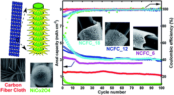
Fig. 5C and D compare the cycle performance of the CFC, NiCo2O4, and three different NiCo2O4/CFC samples in two different ways. The three NiCo2O4/CFC samples were named NCFC_6, NCFC_12 and NCFC_18, in which the loading mass of NiCo2O4 on the CFC was 1.09, 2.25 and 5.09 mg cm−2, respectively. Fig. 5C shows the actual gravimetric capacity of NiCo2O4 in the above three NiCo2O4/CFC samples, and the gravimetric capacity of CFC and NiCo2O4. The actual gravimetric capacity of NiCo2O4 in NiCo2O4/CFC was calculated based on eqn (10).

 
CNiCo2O4= (QtotalCCFCmCFC)/mNiCo2O4 (10)
Here CNiCo2O4 is the gravimetric capacity of NiCo2O4, Qtotal is the measured Coulomb charge, mNiCo2O4 is the mass of NiCo2O4, and CCFC is the gravimetric capacity of CFC. When the current rate was 100 mA g−1, the gravimetric capacity of the CFC was about 95 mA h g−1, while that of NiCo2O4 decayed quickly and then was a similar level to the CFC. The actual gravimetric capacity of NCFC_6 was higher than the theoretical capacity of NiCo2O4 (817 mA h g−1). The higher actual capacity of NiCo2O4 in NiCo2O4/CFC might be ascribed to the synergistic effect between NiCo2O4 and CFC. Furthermore, the mass of CFC was ten times higher than that of NiCo2O4, and variations in the CFC capacity in the control experiment would result in larger fluctuations of the calculated actual capacity. This might be another reason causing the higher actual gravimetric capacity of NiCo2O4. The actual gravimetric capacities of NCFC_12 and NCFC_18 decayed at first and then were 754 and 363 mA h g−1 at the 100th cycle, respectively. The actual gravimetric capacity of NiCo2O4 in NiCo2O4/CFC after cycling decreased when the loading mass increased. The fact that a lower loading mass led to a higher capacity of NiCo2O4 indicated that a lower loading mass of NiCo2O4 on CFC, or a thinner NiCo2O4 layer on the carbon fiber was beneficial to improving the capacity of NiCo2O4.

Along with further developing research on LIBs, it was important to provide the loading mass of the active materials to evaluate their practical use.43 Fig. 5D compares the five anodes in Fig. 5C in the form of the areal capacity of the whole electrode. Although the gravimetric capacities of the NiCo2O4 anode and CFC anode were at a similar level, the lower loading mass of NiCo2O4 (1.07 mg cm−2) made its areal capacity negligible, while the larger loading mass of CFC (14.68 mg cm−2) made that of the CFC 1.16 mA h cm−2. The areal capacities of the three NiCo2O4/CFC samples, NCFC_6, NCFC_12 and NCFC_18 at the 80th cycle, were 2.59, 3.04 and 3.10 mA h cm−2, respectively. The areal capacity of the whole anode was provided by both the CFC and the NiCo2O4 layer covering it. When the loading mass of NiCo2O4 in NiCo2O4/CFC was low, the contribution of the CFC was almost close to that of NiCo2O4 in NiCo2O4/CFC. However, it was observed that the areal capacity of the NiCo2O4/CFC anode could be improved slightly by sacrificing the dosage of NiCo2O4 in this work.

The rate capability of the NiCo2O4/CFC anode is demonstrated in Fig. 5E and S6E. The loading mass of NiCo2O4 on the CFC in the NiCo2O4/CFC sample was 2.99 mg cm−2. The anode ran 10 cycles at five current rates and then another 100 cycles at the first current again. The experimental results showed that the discharge capacity of the NiCo2O4/CFC anode decreased from 4.57 mA h cm−2 (1529 mA h g−1) to 2.68 mA h cm−2 (898 mA h g−1) at a current rate of 100 mA g−1, and it was about 2.17, 1.98, 1.81 and 1.69 mA h cm−2 at current rates of 200, 300, 400 and 500 mA g−1, respectively. Then, when the current rate returned to 100 mA g−1, the anode of NiCo2O4/CFC continued to run for another 100 discharge/charge cycles (Fig. S6E). Its discharge capacity was found to be 2.42 mA h cm−2 at the 51st cycle, and then slowly decreased to 2.39 mA h cm−2 at the 150th cycle, during which the CE of most cycles was above 99.4%. Therefore, it could be concluded that the anode had a stable capacity over 100 cycles at a higher areal mass loading.

Electrochemical impedance spectroscopy (EIS) was used to compare the electrochemical kinetics difference of the NiCo2O4/CFC anodes before and after cycling. The Nyquist plots (Fig. 5F and S7) consist of a semicircle in the middle frequency region and an inclined line in the low frequency region. The diameter of the semicircle and the slope of the inclined line can be decoded as the charge transfer resistance (Rct) and the Warburg resistance (W), which represent the charge transfer at the interface and the diffusion of the redox species in the electrode, respectively. EIS data was fitted to the equivalent circuit44,45 inset in the figure, and the fitting results are listed in Table S1. The Rct value of NiCo2O4/CFC with different loading mass was obviously lower than that of NiCo2O4, which should be a result of the superior conductivity of CFC. The small difference in the Rct values of NiCo2O4/CFC with different loading mass should also be ascribed to the influence of CFC. The thickness of the NiCo2O4 layer on the CFC increased when the NiCo2O4/CFC sample was prepared over a long time. Correspondingly, the W value increased when the diffusion path length for lithium ions became longer. Moreover, after cycling at various current rates for 150 cycles, both Rct and W values of NCFC_18 in Fig. S6E increased, which indicated that the diffusion of electrons and Li+ turned out to be slower in the LIB after cycling. The difference would be a result of the structural evolution of NiCo2O4/CFC during the cycling.

The structural stability of the NiCo2O4/CFC anodes was then evaluated via SEM images of anodes after cycling (Fig. 6). The batteries were disassembled inside a glovebox, and the anodes were washed with DMC to remove the lithium salts. Although the NiCo2O4 nanoneedles were not easy to distinguish from each other, the NiCo2O4 layer could still cover the carbon fiber (Fig. 6A). This indicated that the NiCo2O4 needle nanoarrays and 1-D carbon fiber could efficiently release the stress from the volumetric change during the discharge/charge process. However, the slits between adjacent NiCo2O4/carbon fibers (Fig. 6B) indicated that the NiCo2O4 layers on adjacent carbon fibers might squeeze each other during the discharge/charge process, and result in the stripping of the NiCo2O4 layer off the CFC substrate and a capacity decay of the active materials. Hence, it might be helpful to improve the capacity of NiCo2O4/CFC by preparing a thinner NiCo2O4 layer on the CFC or weaving a CFC substrate with a larger grid to accommodate the thickness change of the coating.


image file: c5ra19600k-f6.tif
Fig. 6 SEM images of NiCo2O4/CFC after cycling at 100 mA g−1 for 100 cycles at different magnifications.

The electrochemical performance of NiCo2O4/CFC in this work was compared with those of some other NiCo2O4 electrodes reported in previous studies. The calculated results are listed in Table 1, which show that the areal capacity of the NiCo2O4/CFC anode in this work was higher than those of other works. Presumably, the high areal capacity of NiCo2O4/CFC should be ascribed to the following reasons. First, the areal capacity of the whole anode was provided by both NiCo2O4 and the CFC. Second, the electronic conductivity of the CFC was good because it was a carbon material, and that of NiCo2O4 is relatively greater than that of many other transition metal oxides. Third, the mesoporous structure of NiCo2O4 could facilitate the transfer of the charge and the ions. Fourth, the robust layer of NiCo2O4 was directly covered onto the CFC without binder and conductive additives, which kept the active material from stripping the current collector. Finally, both the flexible CFC substrate and the free-standing NiCo2O4 nanoarrays could release the stress from the volumetric change during the discharge/charge process to facilitate the stability of the capacity.

Table 1 Electrochemical performances of different NiCo2O4 electrodes
Morphologies Areal capacity (mA h cm−2) Current rate (mA g−1) Loading mass (mg cm−2) Substrate Year Reference
Nanoneedles 2.59 100 1.09 CFC This work
Nanoflakes 1.64 500 2.5 Ni foam 2015 46
Nanowires 0.86 100 2.1 Ni foam 2015 47
Nanosheets 0.77 100 1 Cu foil 2015 48
Nanoflakes 0.88 500 1 Cu foil 2014 49
Nanobelts/nanowires 0.98/0.52 500 0.8 Carbon textiles 2014 19


4. Conclusions

In summary, we had fabricated a robust layer of free-standing NiCo2O4 nanoarrays covered on carbon fiber cloth for LIB anodes. The CFC substrate provided a flexible electronic conductive substrate to load NiCo2O4. In addition, the composite synthesis and electrode fabrication processes are simple, and free of binder and conductive reagent. As a result, the NiCo2O4/CFC presented here showed great promise for a high areal capacity anode.

Acknowledgements

This work was financially supported by National Natural Science Foundation of China (21165010, 21465014 and 21465015), Science and Technology Support Program of Jiangxi Province (20123BBE50104 and 20133BBE50008), Natural Science Foundation of Jiangxi Province (20142BAB203101), The Ministry of Education by the Specialized Research Fund for the Doctoral Program of Higher Education (20133604110002) and the Ground Plan of Science and Technology Projects of Jiangxi Educational Committee (KJLD14023), Innovation Foundation for graduate student of Jiangxi Province and Jiangxi Normal University (YC2013-B026) and Scientific Research Funds of Jiangxi Normal University (No. 5487).

Notes and references

  1. A. Marschilok, C.-Y. Lee, A. Subramanian, K. J. Takeuchi and E. S. Takeuchi, Energy Environ. Sci., 2011, 4, 2943–2951 CAS.
  2. S. Lee, D. Cho and Y. Jeong, Fibers Polym., 2015, 16, 1600–1604 CrossRef CAS.
  3. L. S. Zhang, W. Fan and T. X. Liu, RSC Adv., 2015, 5, 43130–43140 RSC.
  4. C. Wang, D. Li, C. O. Too and G. G. Wallace, Chem. Mater., 2009, 21, 2604–2606 CrossRef CAS.
  5. B. Liu, J. Zhang, X. Wang, G. Chen, D. Chen, C. Zhou and G. Shen, Nano Lett., 2012, 12, 3005–3011 CrossRef CAS PubMed.
  6. L. Yue, H. Zhong and L. Zhang, Electrochim. Acta, 2012, 76, 326–332 CrossRef CAS.
  7. M. S. Balogun, M. H. Yu, C. Li, T. Zhai, Y. Liu, X. H. Lu and Y. X. Tong, J. Mater. Chem. A, 2014, 2, 10825–10829 CAS.
  8. M. S. Balogun, C. Li, Y. X. Zeng, M. H. Yu, Q. L. Wu, M. M. Wu, X. H. Lu and Y. X. Tong, J. Power Sources, 2014, 272, 946–953 CrossRef CAS.
  9. M. S. Balogun, M. H. Yu, Y. C. Huan, C. Li, P. P. Fang, Y. Li, X. H. Lu and Y. X. Tong, Nano Energy, 2015, 11, 348–355 CrossRef CAS.
  10. G. Zhou, F. Li and H.-M. Cheng, Energy Environ. Sci., 2014, 7, 1307–1338 CAS.
  11. Y. Z. Wan, Z. W. Yang, G. Y. Xiong, R. S. Guo, Z. Liu and H. L. Luo, J. Power Sources, 2015, 294, 414–419 CrossRef CAS.
  12. T. V. Thi, A. K. Rai, J. Gim and J. Kim, J. Power Sources, 2015, 292, 23–30 CrossRef CAS.
  13. H. B. Geng, X. Q. Cao, Y. Zhang, K. M. Geng, G. L. Qu, M. H. Tang, J. W. Zheng, Y. G. Yang and H. W. Gu, J. Power Sources, 2015, 294, 465–472 CrossRef CAS.
  14. H. Fang, S. C. Zhang, W. B. Liu, Z. J. Du, X. M. Wu and Y. L. Xing, Electrochim. Acta, 2013, 108, 651–659 CrossRef CAS.
  15. Q. T. Qu, T. Gao, H. Y. Zheng, X. X. Li, H. M. Liu, M. Shen, J. Shao and H. H. Zheng, Carbon, 2015, 92, 119–125 CrossRef CAS.
  16. J. Xu, L. He, W. Xu, H. Tang, H. Liu, T. Han, C. Zhang and Y. Zhang, Electrochim. Acta, 2014, 145, 185–192 CrossRef CAS.
  17. C. C. Sun, J. Yang, X. H. Rui, W. N. Zhang, Q. Y. Yan, P. Chen, F. W. Huo, W. Huang and X. C. Dong, J. Mater. Chem. A, 2015, 3, 8483–8488 CAS.
  18. H. S. Jadhav, R. S. Kalubarme, C.-N. Park, J. Kim and C.-J. Park, Nanoscale, 2014, 6, 10071–10076 RSC.
  19. L. Shen, Q. Che, H. Li and X. Zhang, Adv. Funct. Mater., 2014, 24, 2630–2637 CrossRef CAS.
  20. L. Zhang, S. Zhang, K. Zhang, G. Xu, X. He, S. Dong, Z. Liu, C. Huang, L. Gu and G. Cui, Chem. Commun., 2013, 49, 3540–3542 RSC.
  21. W.-M. Liu, T.-T. Gao, Y. Yang, Q. Sun and Z.-W. Fu, Phys. Chem. Chem. Phys., 2013, 15, 15806–15810 RSC.
  22. Y. Chen, B. Qu, L. Hu, Z. Xu, Q. Li and T. Wang, Nanoscale, 2013, 5, 9812–9820 RSC.
  23. Q. Zhang, H. Chen, J. Wang, D. Xu, X. Li, Y. Yang and K. Zhang, ChemSusChem, 2014, 7, 2325–2334 CrossRef CAS PubMed.
  24. Z. Lu, N. Liu, H.-W. Lee, J. Zhao, W. Li, Y. Li and Y. Cui, ACS Nano, 2015, 9, 2540–2547 CrossRef CAS.
  25. E. Peled, F. Patolsky, D. Golodnitsky, K. Freedman, G. Davidi and D. Schneier, Nano Lett., 2015, 15, 3907–3916 CrossRef CAS.
  26. J.-S. Kim, D. Ko, D.-J. Yoo, D. S. Jung, C. T. Yavuz, N.-I. Kim, I.-S. Choi, J. Y. Song and J. W. Choi, Nano Lett., 2015, 15, 2350–2357 CrossRef CAS PubMed.
  27. B. Wang, X. Li, B. Luo, Y. Jia and L. Zhi, Nanoscale, 2013, 5, 1470–1474 RSC.
  28. K. H. Seng, J. Liu, Z. P. Guo, Z. X. Chen, D. Jia and H. K. Liu, Electrochem. Commun., 2011, 13, 383–386 CrossRef CAS.
  29. S. Chen, J. Wu, R. Zhou, L. Zuo, P. Li, Y. Song and L. Wang, Electrochim. Acta, 2015, 180, 78–85 CrossRef CAS.
  30. Y. D. Zhang, Z. G. Hu, Y. R. Liang, Y. Y. Yang, N. An, Z. M. Li and H. Y. Wu, J. Mater. Chem. A, 2015, 3, 15057–15067 CAS.
  31. H. L. Yu, C. L. Zhu, K. Zhang, Y. J. Chen, C. Y. Li, P. Gao, P. P. Yang and Q. Y. Ouyang, J. Mater. Chem. A, 2014, 2, 4551–4557 CAS.
  32. J. Xiao and S. Yang, RSC Adv., 2011, 1, 588–595 RSC.
  33. J. Li, S. Xiong, Y. Liu, Z. Ju and Y. Qian, ACS Appl. Mater. Interfaces, 2013, 5, 981–988 CAS.
  34. N. Garg, M. Basu and A. K. Ganguli, J. Phys. Chem. C, 2014, 118, 17332–17341 CAS.
  35. N. Padmanathan and S. Selladurai, RSC Adv., 2014, 4, 8341–8349 RSC.
  36. H. Shi and G. Zhao, J. Phys. Chem. C, 2014, 118, 25939–25946 CAS.
  37. M. Dirican, O. Yildiz, Y. Lu, X. Fang, H. Jiang, H. Kizil and X. Zhang, Electrochim. Acta, 2015, 169, 52–60 CrossRef CAS.
  38. W. Xiong, Y. Gao, X. Wu, X. Hu, D. Lan, Y. Chen, X. Pu, Y. Zeng, J. Su and Z. Zhu, ACS Appl. Mater. Interfaces, 2014, 6, 19416–19423 CAS.
  39. Y. Luo, M. S. Balogun, W. T. Qiu, R. R. Zhao, P. Liu and Y. X. Tong, Chem. Commun., 2015, 51, 13016–13019 RSC.
  40. D. Kong, J. Luo, Y. Wang, W. Ren, T. Yu, Y. Luo, Y. Yang and C. Cheng, Adv. Funct. Mater., 2014, 24, 3815–3826 CrossRef CAS.
  41. L. Li, Y. Cheah, Y. Ko, P. Teh, G. Wee, C. Wong, S. Peng and M. Srinivasan, J. Mater. Chem. A, 2013, 1, 10935–10941 CAS.
  42. M.-S. Balogun, M. Yu, C. Li, T. Zhai, Y. Liu, X. Lu and Y. Tong, J. Mater. Chem. A, 2014, 2, 10825–10829 CAS.
  43. M. Zhou, X. Li, B. Wang, Y. Zhang, J. Ning, Z. Xiao, X. Zhang, Y. Chang and L. Zhi, Nano Lett., 2015, 15, 6222–6228 CrossRef CAS PubMed.
  44. L. N. Gao, X. F. Wang, Z. Xie, W. F. Song, L. J. Wang, X. Wu, F. Y. Qu, D. Chen and G. Z. Shen, J. Mater. Chem. A, 2013, 1, 7167–7173 CAS.
  45. C. Wang, W. Wan, Y. H. Huang, J. T. Chen, H. H. Zhou and X. X. Zhang, Nanoscale, 2014, 6, 5351–5358 CAS.
  46. Q. Zheng, X. Zhang and Y. Shen, Mater. Res. Bull., 2015, 63, 211–215 CrossRef CAS.
  47. G. Chen, J. Yang, J. Tang and X. Zhou, RSC Adv., 2015, 5, 23067–23072 RSC.
  48. A. K. Mondal, D. Su, S. Chen, K. Kretschmer, X. Xie, H.-J. Ahn and G. Wang, ChemPhysChem, 2015, 16, 169–175 CrossRef CAS.
  49. A. K. Mondal, D. Su, S. Chen, X. Xie and G. Wang, ACS Appl. Mater. Interfaces, 2014, 6, 14827–14835 CAS.

Footnote

Electronic supplementary information (ESI) available: Electrochemical performances of carbon fiber cloth and NiCo2O4 NPs. See DOI: 10.1039/c5ra19600k

This journal is © The Royal Society of Chemistry 2015
Click here to see how this site uses Cookies. View our privacy policy here.