High-performance NaA zeolite membranes supported on four-channel ceramic hollow fibers for ethanol dehydration
Dezhong Liu,
Yuting Zhang,
Ji Jiang,
Xuerui Wang,
Chun Zhang and
Xuehong Gu*
State Key Laboratory of Materials-Oriented Chemical Engineering, College of Chemical Engineering, Nanjing Tech University, 5 Xinmofan Road, Nanjing 210009, P. R. China. E-mail: Xuehonggu@yahoo.com; Fax: +86-25-83172268; Tel: +86-25-83172268
First published on 3rd November 2015
Abstract
NaA zeolite membranes were prepared on an external surface of novel four-channel α-Al2O3 hollow fiber (4CF) supports for pervaporation dehydration of ethanol. The 4CF supports were first seeded with ball-milled NaA zeolite seeds by a dip-coating approach and followed by hydrothermal crystallization at 100 °C for 4 h. Influences of the seeding condition and microstructure of the 4CF supports were extensively investigated. The separation performances of the as-synthesized membranes were evaluated by pervaporation dehydration of 90 wt% ethanol/water mixtures at 75 °C. A notably high water permeation flux of 12.8 kg m−2 h−1 and a separation factor of >10![[thin space (1/6-em)]](https://www.rsc.org/images/entities/char_2009.gif) 000 was obtained in the membrane supported on 4CF which had a porosity of 55% as well as a high mechanical strength of 18 N. In comparison with single-channel α-Al2O3 hollow fiber supported NaA zeolite membranes, the 4CF supported membranes were considerably superior in permeation flux, mechanical strength and convenience of seeding operation. Allowing for high reproducibility as well as high performance, there would be great potential in industrial applications for 4CF-supported NaA zeolite membranes.
000 was obtained in the membrane supported on 4CF which had a porosity of 55% as well as a high mechanical strength of 18 N. In comparison with single-channel α-Al2O3 hollow fiber supported NaA zeolite membranes, the 4CF supported membranes were considerably superior in permeation flux, mechanical strength and convenience of seeding operation. Allowing for high reproducibility as well as high performance, there would be great potential in industrial applications for 4CF-supported NaA zeolite membranes.
1. Introduction
Pervaporation (PV) is a promising membrane process for liquid-phase separation with high efficiency. NaA zeolite membranes, with strong hydrophilicity and well-defined micro-pores (∼0.42 nm), exhibit extremely high selectivity for PV dehydration of organic solutions, especially for alcohol, an essential product applied in petrochemical, pharmaceutical, fine chemical and new energy industries. To date, tubular NaA zeolite membranes have been commercialized by a few companies, such as Mitsui Engineering & Shipbuilding (Japan), GFT-Inocermic (Germany) and Jiangsu Nine-Heaven (China) in corporation with our group.1,2 However, the high fabrication cost and low permeation flux for tubular NaA zeolite membranes have restricted their widely industrial applications.3 Porous ceramic hollow fibers have recently been considered as excellent substrates for supporting zeolite membranes. The thin substrate wall (<0.5 mm) and the finger-like structure provides low transfer resistance for component permeation, which can improve the permeation flux through zeolite membranes significantly. Moreover, the membrane modules comprising hollow fiber membranes have a notably high packing density, resulting in a reduced fabrication cost for separation equipment.Xu et al.4 first reported the synthesis of NaA zeolite membranes on ceramic hollow fibers by repeating the process three times; however, they did not provide the dehydration performance. Recently, Wang and co-workers5 reported NaA zeolite membranes supported by α-Al2O3 hollow fibers and polymer–zeolite composite hollow fibers with permeation fluxes of >9.0 kg m−2 h−1 for dehydration of 90 wt% ethanol/water mixtures at 75 °C, which were three to five times higher than those fluxes for tubular NaA zeolite membranes reported in the literature.6,7 The seeding quality has been found to impact on the growth of NaA zeolite membranes significantly.7 Conventional seeding approaches, such as rubbing and dip-coating, were not suitable for producing high-performance hollow-fiber supported NaA zeolite membranes. This is strongly related with the inherent properties of porous hollow fibers, e.g., small diameter and thin thickness wall, which leads to a non-uniform seed layer for rubbing or low capillary water suction capacity for dip-coating. Combined dip-coating and wiping was recommended to prepare high-quality hollow-fiber supported NaA zeolite membranes by Wang and co-workers,5 but the manual and complicated process is not practical for large-scale production of the membranes. To address the issue, our group reported a vacuum seeding method for preparation of hollow fiber supported NaA and T-type zeolite membranes, which showed great potential in batch-scale production.8,9 However, the high brittleness as well as low fracture load is still a main obstacle for industrial applications for the current hollow fiber membranes.
Recently, we successfully prepared four-channel porous Al2O3 hollow fibers (4CFs) with great mechanical strength and permeability.10 In this work, we reported the synthesis of NaA zeolite membranes on four-channel ceramic hollow fibers. We will show that the as-synthesized membranes exhibited ultra-high permeation flux except for high mechanical strength. It should be also noted that the membranes could be reproducibly synthesized with a facile seeding method via dip-coating, which opens the possibility for large-scale production of hollow-fiber-supported zeolite membranes.
2. Experimental
2.1. Preparation of porous hollow fibers
The 4CF substrates were prepared with a dry-wet spinning technique.10,11 α-Al2O3 powders (d50 = 0.8 μm, Hai-Gang-Hua-Tai functional ceramics Co., Ltd.), polyethersulfone (PESf, BD-5, Bei-Shi-De synthetic plastics company), n-methyl-2-pyrrolidone (NMP, ≥98%, Sinopharm Chemical Reagent Co., Ltd.) and polyvinylpyrrolidone (PVP, ≥95%, Sinopharm Chemical Reagent Co., Ltd.) were respectively used as synthetic material, binder, solvent and additive for spinning suspension, which had a mass ratio of α-Al2O3![[thin space (1/6-em)]](https://www.rsc.org/images/entities/char_2009.gif) :
:![[thin space (1/6-em)]](https://www.rsc.org/images/entities/char_2009.gif) PESf
PESf![[thin space (1/6-em)]](https://www.rsc.org/images/entities/char_2009.gif) :
:![[thin space (1/6-em)]](https://www.rsc.org/images/entities/char_2009.gif) NMP
NMP![[thin space (1/6-em)]](https://www.rsc.org/images/entities/char_2009.gif) :
:![[thin space (1/6-em)]](https://www.rsc.org/images/entities/char_2009.gif) PVP = 49.7
PVP = 49.7![[thin space (1/6-em)]](https://www.rsc.org/images/entities/char_2009.gif) :
:![[thin space (1/6-em)]](https://www.rsc.org/images/entities/char_2009.gif) 9.94
9.94![[thin space (1/6-em)]](https://www.rsc.org/images/entities/char_2009.gif) :
:![[thin space (1/6-em)]](https://www.rsc.org/images/entities/char_2009.gif) 39.83
39.83![[thin space (1/6-em)]](https://www.rsc.org/images/entities/char_2009.gif) :
:![[thin space (1/6-em)]](https://www.rsc.org/images/entities/char_2009.gif) 0.53. After degassing, the spinning suspension was extruded through a designed four-bore spinneret. The as-generated hollow fiber precursors were subsequently immersed into an external coagulant (tap water) for phase inversion. The air gap was kept at 10 cm for all spinning runs. The extrusion rate of the suspension and the flow rate of the internal coagulant (deionized water) were kept at 1.35 mL min−1 and 40 mL min−1, respectively. The green hollow fibers were left in the external coagulant for complete solidification. After drying, the green hollow fibers were sintered at high temperatures between 1350 to 1550 °C for 5 h. For comparison, single-channel hollow fibers (1CFs) were also prepared via a single-bore spinneret using the same synthesis procedure as 4CFs. The detailed preparation procedure was reported in our previous publication.10
0.53. After degassing, the spinning suspension was extruded through a designed four-bore spinneret. The as-generated hollow fiber precursors were subsequently immersed into an external coagulant (tap water) for phase inversion. The air gap was kept at 10 cm for all spinning runs. The extrusion rate of the suspension and the flow rate of the internal coagulant (deionized water) were kept at 1.35 mL min−1 and 40 mL min−1, respectively. The green hollow fibers were left in the external coagulant for complete solidification. After drying, the green hollow fibers were sintered at high temperatures between 1350 to 1550 °C for 5 h. For comparison, single-channel hollow fibers (1CFs) were also prepared via a single-bore spinneret using the same synthesis procedure as 4CFs. The detailed preparation procedure was reported in our previous publication.10
2.2. Preparation of NaA zeolite membranes
NaA zeolite membranes were hydrothermally synthesized on external surface of α-Al2O3 hollow fiber substrates by the secondary growth method. Dip-coating approach was used to plant NaA zeolite seeds on external surface of 4CF substrates. The seeds were obtained by milling NaA zeolite powders (average particle size, A.P.S. ∼2.8 μm, homemade) for 6 h with a planetary ball mill (PM-100, Retsch. Ind. Ltd.) using zirconium oxide balls as grinding media, as described in our previous work.12 Before membrane synthesis, the hollow fiber substrates were ultrasonic cleaned by deionized water and then dried in an oven. The substrates were dipped into an aqueous 1.0–2.0 wt% seed suspension containing seed particles (A.P.S. ∼220 nm) for 10 to 20 s. After drying, the seeded substrates were immersed in a synthesis solution for hydrothermal crystallization. The synthesis gel was prepared by dissolving sodium aluminate, sodium hydroxide and water glass into deionized water with the molar ratio of 1Al2O3![[thin space (1/6-em)]](https://www.rsc.org/images/entities/char_2009.gif) :
:![[thin space (1/6-em)]](https://www.rsc.org/images/entities/char_2009.gif) 2SiO2
2SiO2![[thin space (1/6-em)]](https://www.rsc.org/images/entities/char_2009.gif) :
:![[thin space (1/6-em)]](https://www.rsc.org/images/entities/char_2009.gif) 2Na2O
2Na2O![[thin space (1/6-em)]](https://www.rsc.org/images/entities/char_2009.gif) :
:![[thin space (1/6-em)]](https://www.rsc.org/images/entities/char_2009.gif) 120H2O. All the chemicals were industrial grade and purchased from commercial companies in China. Hydrothermal crystallization was performed at 100 °C for 4 h.
120H2O. All the chemicals were industrial grade and purchased from commercial companies in China. Hydrothermal crystallization was performed at 100 °C for 4 h.
2.3. Pervaporation
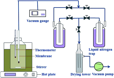
The separation performance of NaA zeolite membranes was evaluated with a PV apparatus, as shown in Fig. 1. One end of the hollow fiber NaA zeolite membrane was sealed with silicone and the other end was connected to a vacuum line. The membrane was immersed in the feed tank, which was filled with approximately 2 L of 90 wt% ethanol/water mixture. The inside of the membrane was evacuated by a vacuum pump, and the pressure was maintained below 200 Pa. The permeated vapors were collected using cold traps cooled by liquid nitrogen. Both the feed and the permeate were analyzed by a gas chromatograph (GC-2014, Shimadzu) equipped with a thermal conductivity detector and a packed column of Parapak-Q (All-tech). The PV performance of each of the membranes was determined by separation factor (α) and water permeation flux (J), which are respectively defined as follows:
 | (1) |
 | (2) |
2.4. Characterizations
The textures of porous hollow fibers and membranes were observed by a scanning electron microscopy (SEM, S4800, Hitachi). The porosities of hollow fibers were measured based on a gravimetric analysis of the water entrapped in the pores. The average pore size was measured by a bubble point apparatus set up in our laboratory. The mechanical strengths of hollow fibers were characterized by a three-point bending instrument (CMI6203, Shenzhen Xin-San-Si Co., Ltd.) using a length of 4 cm. The fracture load was adopted to evaluate the mechanical strengths of 1CFs and 4CFs.3. Results and discussion
3.1. Comparison of NaA zeolite membranes supported on 1CFs and 4CFs
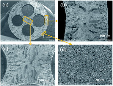
The SEM images of a 4CF substrate sintered at 1400 °C are shown in Fig. 2. The four round channels were formed uniformly with inter-connected structure (Fig. 2a). Some finger-like voids were embedded at either the inner or outer edge (Fig. 2b) due to rapid precipitation of precursor during phase inversion. The appearance of the sponge-like structure at the center of the wall can be attributed to slow precipitation. More figure-like regions were embedded in the inter-connected structure (Fig. 2c). It is interesting to observe that the 4CF has a relatively smooth outer surface and uniform surface pores (Fig. 2d), which is suitable for membrane growth. Table 1 presents the properties of a 1CF and a 4CF sintered at 1400 °C for 5 h. A fracture load of 18 N was achieved for the as-made 4CF, which was approximately 5.2 times of that for the 1CF sintered at the same condition. The inter-connected structure should make an important contribution to the high mechanical strength for the 4CF, as discussed in our previous publication.10 The 4CF produced in this work was found to exhibit a very high porosity of >50%, which was higher than the 1CF. The four channel of hollow fiber with higher internal surface area/weight ratio can promote the solvent/non-solvent exchange. This may explain why the 4CF has a high porosity. The substrate surface had an average pore size of ∼0.87 μm.The 4CFs were further used for preparation of NaA zeolite membranes by the secondary growth method. The seed layer was very important for membrane growth. To obtain high quality NaA zeolite membrane supported on 4CF, different content of seed suspensions were compared. Fig. 3 shows SEM images of seed layers on 4CFs. When 1.0 wt% seed suspension was used, the low lands of the 4CF were coated well with NaA particles, however, some high lands and the areas with large opening pores were not covered with NaA seeds. The coverage of seed layer was improved when increasing the content of seed suspension. As the seed concentration increased to 2.0 wt%, the substrate was completely covered by seeds and a continuous seed layer was obtained. Some small flaws were generated after drying seed layer, which did not affect membrane growth. Comparatively, sparse seed layer was formed on the surface of 1CF, even 2.0 wt% seed suspension were used. This was due to the low water suction capacity as a result of thin wall thickness for single channel hollow fiber substrates.13
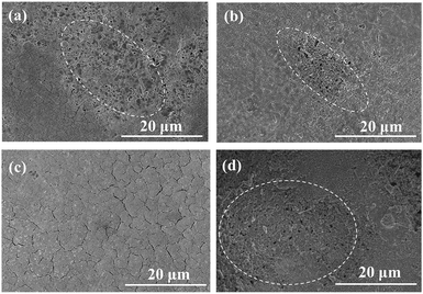 | ||
| Fig. 3 SEM images of the seeded 4CF (a–c) and 1CF (d) by dip-coating with different seed suspensions: 1.0 wt% (a), 1.5 wt% (b), 2.0 wt% (c and d). | ||
Table 2 lists PV performance of as-synthesized NaA zeolite membranes prepared with different content of seed suspensions. The membranes were evaluated by PV dehydration of 90 wt% ethanol/water mixtures at 75 °C. For seed concentration of 1.0 wt%, the as-synthesized membrane showed a αwater/ethanol of below 3000 due to incomplete seed coverage on substrate surface. The selectivity of membrane was improved with increasing the continuity and uniformity of seed layer. A high separation factor of >10![[thin space (1/6-em)]](https://www.rsc.org/images/entities/char_2009.gif) 000 was obtained on the as-synthesized NaA zeolite membrane. Moreover, the 4CF-supported zeolite membrane exhibited an ultra-high water permeation flux of 12.8 kg m−2 h−1. To our knowledge, the water permeation flux was highest among the reported results at the same operating condition (Table 3). The high water permeation flux for the 4CF-supported membrane was attributed to the ultra-thin substrate wall and high porosity with finger-like voids. Moreover, the four-channel lumen also reduced the transfer resistance for water diffusion under vacuum condition. We realized that the synthesis approach exhibited very good reproducibility for obtaining both high flux and high separation factor, which was confirmed by batch-scale synthesis. The SEM images of 4CF-supported NaA zeolite membrane by the use of 2.0 wt% seed concentration were shown in Fig. 4. NaA zeolite membrane was formed on the external surface of 4CF, which had well-intergrown zeolite layer with thickness of 3–4 μm (Fig. 4a and b). To reveal the importance of the four-channel geometric configuration, we also prepared NaA zeolite membranes on 1CFs via the dip-coating seeding approach. Unfortunately, the 1CF supported NaA zeolite membranes exhibited a very low separation factor of below 1000. This was due to the low seed coverage on external surface of 1 CF as discussed above, which was not good enough for induction of dense zeolite layer. To improve the seed coverage on 1CF by dip-coating, Shao et al.13 attempted to use nano-sized NaA zeolite particles for seeding. However, the main drawback for the 1CF supported NaA zeolite membranes is the low mechanical strength, which is not enough for practical applications.
000 was obtained on the as-synthesized NaA zeolite membrane. Moreover, the 4CF-supported zeolite membrane exhibited an ultra-high water permeation flux of 12.8 kg m−2 h−1. To our knowledge, the water permeation flux was highest among the reported results at the same operating condition (Table 3). The high water permeation flux for the 4CF-supported membrane was attributed to the ultra-thin substrate wall and high porosity with finger-like voids. Moreover, the four-channel lumen also reduced the transfer resistance for water diffusion under vacuum condition. We realized that the synthesis approach exhibited very good reproducibility for obtaining both high flux and high separation factor, which was confirmed by batch-scale synthesis. The SEM images of 4CF-supported NaA zeolite membrane by the use of 2.0 wt% seed concentration were shown in Fig. 4. NaA zeolite membrane was formed on the external surface of 4CF, which had well-intergrown zeolite layer with thickness of 3–4 μm (Fig. 4a and b). To reveal the importance of the four-channel geometric configuration, we also prepared NaA zeolite membranes on 1CFs via the dip-coating seeding approach. Unfortunately, the 1CF supported NaA zeolite membranes exhibited a very low separation factor of below 1000. This was due to the low seed coverage on external surface of 1 CF as discussed above, which was not good enough for induction of dense zeolite layer. To improve the seed coverage on 1CF by dip-coating, Shao et al.13 attempted to use nano-sized NaA zeolite particles for seeding. However, the main drawback for the 1CF supported NaA zeolite membranes is the low mechanical strength, which is not enough for practical applications.
| Membrane | Seed concentration (wt%) | J (kg m−2 h−1) | αwater/ethanol |
|---|---|---|---|
| 4CF-01 | 1.0 | 11.3 | 1139 |
| 4CF-02 | 1.0 | 11.8 | 3075 |
| 4CF-03 | 1.0 | 8.9 | 1202 |
| 4CF-04 | 1.5 | 10.0 | 2050 |
| 4CF-05 | 1.5 | 10.6 | >10![[thin space (1/6-em)]](https://www.rsc.org/images/entities/char_2009.gif) 000 000 |
| 4CF-06 | 1.5 | 12.4 | 2779 |
| 4CF-07 | 2.0 | 12.8 | >10![[thin space (1/6-em)]](https://www.rsc.org/images/entities/char_2009.gif) 000 000 |
| 4CF-08 | 2.0 | 11.0 | >10![[thin space (1/6-em)]](https://www.rsc.org/images/entities/char_2009.gif) 000 000 |
| 4CF-09 | 2.0 | 10.4 | >10![[thin space (1/6-em)]](https://www.rsc.org/images/entities/char_2009.gif) 000 000 |
| 1CF-10 | 2.0 | 12.0 | 100 |
| 1CF-11 | 2.0 | 9.4 | 179 |
| 1CF-12 | 2.0 | 12.9 | 700 |
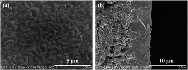 | ||
| Fig. 4 SEM images of the surface (a) and cross-sections (b) of 4CF-supported NaA zeolite membrane by the use of 2.0 wt% seed suspension. | ||
3.2. Influence of substrate microstructure of 4CF
It is well recognized the substrate properties plays important roles for PV performance.14,15 We investigated the relationship between substrate microstructure and PV performance for 4CF-supported NaA zeolite membranes. To obtain hollow fibers with different porosities, green 4CFs were sintered at different temperatures, producing the porosities between 40 to 65% and average pore sizes in the range of 0.60 to 0.97 μm. Fig. 5 shows the PV performance of NaA zeolite membranes with different porosities. As can be seen, the water permeation flux increased linearly with substrate porosity. A water permeation flux as high as 17.8 kg m−2 h−1 could be achieved on the membrane supported by the substrate with a porosity of 65.5%. However, the separation factor decreased to 1400 due to too large substrate pores, which is not good for membrane growth. Shao et al.15 pointed out a pervaporation flux of 11.1 kg m−2 h−1 was achieved when the support porosity increases to 69%. These results indicated that the transfer resistance through hollow fiber substrates had a significant effect on water permeation for pervaporation operation.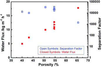 | ||
| Fig. 5 Effect of 4CF porosity on the PV performance of as-synthesized NaA zeolite membranes (PV condition: 90 wt% ethanol/water mixture at 75 °C). | ||
For PV process, the permeate side faced to substrate side was operated at vacuum environment, which resulted in large mean free path for components diffusing through substrate pores. For example, it is around 271 μm for H2O at 200 Pa and 75 °C,16 which is much larger than the pore size of sponge region at 4CF substrates (usually 0.5–1.0 μm). Thus, Knudsen diffusion makes an important contribution to component diffusion through sponge-like structure. In this way, molecule diffusion is related with the collisions between molecules and pore walls. Korelskiy et al.17 pointed out the mass transfer resistance in the support layer share 25–60% contribution to the total mass transfer resistance for n-butanol or water pass through MFI zeolite membrane by the combination of experiment and simulation analysis. The results indicate the transfer resistance in supporting layer plays a very important role in the water permeation flux of zeolite membrane for PV process.
3.3. PV performance
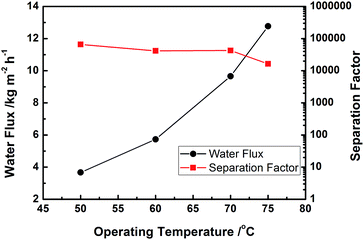
We further studied the effect of operating temperature on the PV performance over a 4CF-supported NaA zeolite membrane. As shown in Fig. 6, with the operating temperature increased from 50 to 75 °C, the water permeation flux increased while the separation factor always remained at a high level of >10![[thin space (1/6-em)]](https://www.rsc.org/images/entities/char_2009.gif) 000. The adsorption–diffusion mechanism dominated the water permeation through the 4CF-supported NaA zeolite membrane.18–20 The elevated temperature could enhance water diffusion, while the water adsorption amount on the feed side varied slightly due to the combined effect of increased water fugacity and reduced adsorption coefficient over the zeolite surface. The linear Arrhenius plots of flux vs. temperature are presented in Fig. 7. The apparent activation energies for water and ethanol permeation through 4CF-supported NaA zeolite membrane were calculated to be 46.5 kJ mol−1 and 88.4 kJ mol−1, respectively, based on the Arrhenius equation. The value of activation energy for water flux was similar to that reported by Pera-Titus et al.21 (41–43 kJ mol−1 for feed water concentration varying from 2.5–59 wt%) and Shah et al.22 (45.6 kJ mol−1 for feed water fractions in the range of 10–100 wt%). The results indicate that ethanol molecules are more difficult to diffuse through NaA zeolitic pores than water molecules and the water permeation through NaA zeolite membrane is independent of the ethanol concentration in the feed.
000. The adsorption–diffusion mechanism dominated the water permeation through the 4CF-supported NaA zeolite membrane.18–20 The elevated temperature could enhance water diffusion, while the water adsorption amount on the feed side varied slightly due to the combined effect of increased water fugacity and reduced adsorption coefficient over the zeolite surface. The linear Arrhenius plots of flux vs. temperature are presented in Fig. 7. The apparent activation energies for water and ethanol permeation through 4CF-supported NaA zeolite membrane were calculated to be 46.5 kJ mol−1 and 88.4 kJ mol−1, respectively, based on the Arrhenius equation. The value of activation energy for water flux was similar to that reported by Pera-Titus et al.21 (41–43 kJ mol−1 for feed water concentration varying from 2.5–59 wt%) and Shah et al.22 (45.6 kJ mol−1 for feed water fractions in the range of 10–100 wt%). The results indicate that ethanol molecules are more difficult to diffuse through NaA zeolitic pores than water molecules and the water permeation through NaA zeolite membrane is independent of the ethanol concentration in the feed.
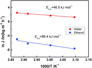 | ||
| Fig. 7 Arrhenius plots of the water and ethanol permeation fluxes through the NaA zeolite membrane (4CF-07). | ||
4. Conclusions
NaA zeolite membranes were prepared successfully on external surface of 4CFs via a seeding approach of dip-coating that is more suitable for batch-scale production. Ultra-high permeation flux of 12.8 kg m−2 h−1 with a remarkable separation factor of >10![[thin space (1/6-em)]](https://www.rsc.org/images/entities/char_2009.gif) 000 was obtained for dehydration of 90 wt% ethanol at 75 °C. The 4CF supported membranes exhibit high mechanical strength, which exhibit great potential in practical applications. The novel 4CF-supported NaA zeolite membranes could significantly reduce facility investment due to both the high permeation flux and the high packing density, which makes PV technology economically feasible for a great number of application fields.
000 was obtained for dehydration of 90 wt% ethanol at 75 °C. The 4CF supported membranes exhibit high mechanical strength, which exhibit great potential in practical applications. The novel 4CF-supported NaA zeolite membranes could significantly reduce facility investment due to both the high permeation flux and the high packing density, which makes PV technology economically feasible for a great number of application fields.
Acknowledgements
This work is sponsored by the National Natural Science Foundation of China (21222602, 21490585 and 21176117), the National High-tech R&D Program of China (2015AA03A602), the Key Project of Chinese Ministry of Education (212060), the Outstanding Young Fund of Jiangsu Province (BK2012040), the Young Fund of Jiangsu Province (BK20130915) and the “Six Top Talents” and “333 Talent Project” of Jiangsu Province.References
- J. Gascon, F. Kapteijn, B. Zornoza, V. C. Sebastian and J. Coronas, Chem. Mater., 2012, 24, 2829–2844 CrossRef CAS.
- J. Caro and M. Noack, Microporous Mesoporous Mater., 2008, 15, 215–233 CrossRef.
- M. Tsapatsis, Science, 2011, 334, 767–768 CrossRef CAS PubMed.
- X. Xu, W. Yang, J. Liu, L. Lin, N. Stroh and H. Brunner, J. Membr. Sci., 2004, 229, 81–85 CrossRef CAS.
- Z. Wang, Q. Ge, J. Shao and Y. Yan, J. Am. Chem. Soc., 2009, 131, 6910–6911 CrossRef CAS PubMed.
- M. Kondo, M. Komori, H. Kita and K. Okamoto, J. Membr. Sci., 1997, 133, 133–141 CrossRef CAS.
- Y. Liu, Z. Yang, C. Yu, X. Gu and N. Xu, Microporous Mesoporous Mater., 2011, 143, 348–356 CrossRef CAS.
- Y. Liu, X. Wang, Y. Zhang, Y. He and X. Gu, Chin. J. Chem. Eng., 2015, 23, 1114–1122 CrossRef CAS.
- X. Wang, Y. Chen, C. Zhang, X. Gu and N. Xu, J. Membr. Sci., 2014, 455, 294–304 CrossRef CAS.
- Z. Shi, Y. Zhang, C. Cai, C. Zhang and X. Gu, Ceram. Interfaces, 2015, 41, 1333–1339 CrossRef CAS.
- B. Kingsbury and K. Li, J. Membr. Sci., 2009, 328, 134–140 CrossRef CAS.
- Z. Yang, Y. Liu, C. Yu, X. Gu and N. Xu, J. Membr. Sci., 2012, 392, 18–28 CrossRef.
- J. Shao, Q. Ge, L. Shan, Z. Wang and Y. Yan, Ind. Eng. Chem. Res., 2011, 50, 9718–9726 CrossRef CAS.
- Q. Ge, Z. Wang and Y. Yan, J. Am. Chem. Soc., 2009, 131, 17056–17057 CrossRef CAS PubMed.
- J. Shao, Z. Zhan, J. Li, Z. Wang, K. Li and Y. Yan, J. Membr. Sci., 2014, 451, 10–17 CrossRef CAS.
- O. Trifunović and G. Trägårdh, J. Membr. Sci., 2005, 259, 122–134 CrossRef.
- D. Korelskiy, T. Leppajarvi, H. Zhou, M. Grahn, J. Tanskanen and J. Hedlund, J. Membr. Sci., 2013, 427, 381–389 CrossRef CAS.
- K. Sato and T. Nakane, J. Membr. Sci., 2007, 301, 151–161 CrossRef CAS.
- T. Bowen, R. Noble and J. Falconer, J. Membr. Sci., 2004, 245, 1–33 CrossRef CAS.
- S. Guo, C. Yu, X. Gu, W. Jin, J. Zhong and C. Chen, J. Membr. Sci., 2011, 376, 40–49 CrossRef CAS.
- M. Pera-Titus, J. Llorens, J. Tejero and F. Cunill, Catal. Today, 2006, 118, 73–84 CrossRef CAS.
- D. Shah, K. Kissick, A. Ghorpade, R. Hannah and D. Bhattacharyya, J. Membr. Sci., 2000, 179, 185–205 CrossRef CAS.
| This journal is © The Royal Society of Chemistry 2015 |

