In situ anchoring uniform MnO2 nanosheets on three-dimensional macroporous graphene thin-films for supercapacitor electrodes†
Yong Zhaoab,
Yuena Menga,
Haiping Wua,
Yue Wanga,
Zhixiang Weia,
Xiaojun Lia and
Peng Jiang*a
aNational Center for Nanoscience and Technology (NCNST), Beijing 100190, China. E-mail: pjiang@nanoctr.cn
bARC Centre of Excellence for Electromaterials Science, Intelligent Polymer Research Institute, AIIM, Innovation Campus, University of Wollongong, NSW 2522, Australia
First published on 14th October 2015
Abstract
We present a facile and efficient fabrication of 3D macroporous rGO/MnO2 nanosheet thin-films for supercapacitor electrodes. An amorphous-carbon-modified rGO thin-film is firstly prepared through a simple glucose and CaCO3 particle mediated template method. Then ultrathin MnO2 nanosheets are in situ synthesized on the rGO networks by the rapid and scalable redox reaction between KMnO4 and amorphous carbon. The fabricated three-dimensional porous hybrid thin-film shows a high specific capacitance of 245 F g−1 (based on the total mass of the film) at a scan rate of 2 mV s−1, a good rate capability of 143 F g−1 at 300 mV s−1, and an excellent cycling stability, maintaining 81% of the initial capacitance after 2000 cycles at 2 A g−1. The improved performance indicates that the lightweight and low-cost 3D porous rGO/MnO2 nanosheet thin-films have a great potential in the area of portable energy storage devices.
Introduction
Supercapacitors, also known as electrochemical capacitors, have attracted enormous attention owing to their excellent properties such as high power density, long cycling life, rapid charge/discharge rates and easy fabrication.1–3 In general, the electrochemical performance of supercapacitors primarily depends on the category and structure of electrode materials. Among the available materials, MnO2 is usually considered as one of the most promising candidates due to its high theoretical capacitance, wide potential window, natural abundance and environmental friendliness.4,5 Given that pseudo-capacitance is primarily generated by surface faradaic redox reactions, developing MnO2 nanostructures with an ultrathin morphology is expected to achieve the full potential of MnO2 for advanced supercapacitors.6–8 However, the poor electrical conductivity of MnO2 (10−5 to 10−6 S cm−1) severely limits its specific capacitance far low from the theoretical value (1340 F g−1).9To overcome this limitation, doping MnO2 with metal10,11 and incorporating MnO2 with highly conductive materials has been extensively investigated over the past decade. Typical conductive backbones used for MnO2 composite electrodes include micro- and nano-networks of metals,3,12,13 carbons14–17 and semiconductors.18–20 Among them, graphene, a two-dimensional sp2-hybridized carbon sheet with one-atom thickness, has been considered as the most promising candidate because of its unique structure and outstanding properties such as large theoretical surface area and high electrical conductivity.21–23 In recent years, various graphene or graphene oxide (GO)/MnO2 composites have been successfully synthesized and utilized as supercapacitor electrodes, such as N-doped graphene/Mn-oxide nanoparticles,24 rGO wrapped CNT–MnO2 nanocables,25 GO/needle-like MnO2,26 graphene-wrapped MnO2 nanospheres,27 N-doped graphene/MnO2 nanosheets,28 graphene/MnO2 nanoparticles,29 graphene/MnO2 nanorods,30 and graphene/MnO2 nanowires.31 However, these composites inevitably suffer from the problems of graphene restacking and MnO2 aggregation during the wet-chemical synthesis and drying processes. In addition, when used as supercapacitor electrodes, they have to be mixed with polymer binders and conductive additives, which will obviously increase the total weight and cost of the integrated devices.
Based on the above considerations, designing three-dimensional (3D) porous graphene micro-networks/MnO2 nanosheets hybrid thin-film electrodes is considerably attractive, for this kind of thin-films can preserve the large ion-accessible surface area and fast electron transport network to fully realize the synergistic effect of graphene and MnO2.32,33 What's more, they are lightweight and inexpensive, and thus quite suitable for the application in portable electronic devices. Recently, several works have been reported to meet the criteria in design of the high-performance graphene/MnO2 thin-film electrodes for supercapacitors. For example, Sun et al.34 developed an asymmetric supercapacitor based on 3D porous ionic liquid–CNT–graphene gel and graphene–MnO2 nanoparticles gel which showed a specific capacity of 256 F g−1 at 1 A g−1. He et al.6 prepared 3D graphene networks/MnO2 composites by growing graphene on Ni-foam via chemical vapour deposition (CVD) method and subsequently electrodepositing MnO2 on it, which achieved a capacitance of 130 F g−1 at a large MnO2 mass loading of 9.8 mg cm−2. Zhang et al.35 prepared sandwich-type porous graphene/CNTs/Mn2O3 electrode by electrochemically depositing manganese oxide on the CVD-based 3D graphene/CNTs composites which exhibited a specific capacity of 370 F g−1 at 0.1 A g−1. By the similar Ni-foam-template CVD method, Sun et al.36 fabricated 3D graphite/MnO2 nanoflakes hybrid electrodes that exhibited a capacitance of 210 F g−1 at the current density of 2 A g−1. But few studies used scalable and low-cost reduced graphene oxide (rGO) as 3D macroporous conductive thin-films to support the MnO2 nanomaterials. The performances of the reported hybrid thin-film electrodes are not satisfying, either. It is still a challenge to uniformly coat MnO2 ultrathin sheets onto 3D porous free-standing rGO thin-films for high-performance supercapacitors.
Herein, we reported a facile and straightforward fabrication of 3D macroporous rGO/MnO2 nanosheets thin-films for supercapacitor electrodes. Amorphous-carbon-modified rGO thin-film (rGO/C) was firstly fabricated via a simple glucose and CaCO3 particles mediated template method. And then ultrathin MnO2 nanosheets were in situ anchored on the rGO networks through the rapid, efficient and scalable redox reaction between amorphous carbon and KMnO4 under hydrothermal conditions. This approach perfectly preserved the free-standing and porous microstructures of the lightweight rGO thin-film. The obtained hybrid thin-film showed a high specific capacitance of 245 F g−1 (based on the total mass of the film) at the scan rate of 2 mV s−1, and a good rate capability of 143 F g−1 at 300 mV s−1. It also exhibited a good cycling stability, remaining 81% of the initial capacitance after 2000 cycles at 2 A g−1. The improved electrochemical performances suggest that the 3D porous rGO/MnO2-nanosheets hybrid thin-films have great potential in the area of portable energy storage devices.
Experimental section
Materials and methods
All the reagents used in the experiment were of analytical grade, and used without further purification. The GO dispersion was synthesized by Hummers’ method.37 The 3D porous rGO/C thin-film was prepared according to the previous report38 with some modifications. Typically, 444 mg of CaCl2 and 36 mg of glucose were added to 18 mL of 1.25 mg mL−1 GO dispersion, then 2.5 mL NH3·H2O were added to the mixture after the solid was completely dissolved. After stirring for 30 min, pure CO2 gas was constantly blown into the reaction system for about 60 min until a khaki suspension was obtained. Then, 6 mL of the suspension was transferred into a vacuum filtration apparatus to form a GO/glucose–CaCO3 film. After drying naturally in air, the composite film was annealed at 600 °C for 6 h in an argon atmosphere to make the GO reduced and the glucose carbonized. Then, the CaCO3 particles were etched by enough diluted HCl solution. After washing with copious deionized (DI) water and ethanol, the free-standing 3D porous rGO/C films were obtained.MnO2 nanosheets were in situ synthesized on the surfaces of rGO/C film based on the following redox reaction between KMnO4 and amorphous carbon under hydrothermal condition (4KMnO4 + 3C + H2O = 4MnO2 + 2KHCO3 + K2CO3). Firstly, a piece of as-obtained rGO/C film (1 × 1 cm2) was put into a 25 mL Teflon-sealed autoclave and carefully flushed by 15 mL of 10 mM KMnO4 aqueous solution to immerse the film into the solution. Then the autoclave was transferred into an oven that had been heated to 180 °C and maintained for 20 minutes. After that, the autoclave was immediately picked out and put into a container with cold running water to stop the hydrothermal reaction. Finally, the autoclave was opened and the resulting rGO/MnO2 thin-film was carefully picked out, rinsed with copious DI water and dried in air at 150 °C for 5 h.
As a control experiment, pure rGO porous film was fabricated successfully without the addition of glucose. A piece of this film (1 × 1 cm2) also underwent the hydrothermal reaction under the same conditions described above.
Characterizations
The morphology was observed under a scanning electron microscopy (SEM, Hitachi S4800) and a transmission electron microscopy (TEM, Tecnai G2 F20 U-TWIN). The X-ray photoelectron spectroscopy (XPS) spectra were measured on an ESCALab 250 electron spectrometer from Thermo Scientific Corporation. The Raman scattering analysis was performed on a confocal microscope-based Raman spectrometer (Renishaw InVia, 633 nm excitation laser).Electrochemical measurements
The as-obtained porous rGO/MnO2 thin-film was cut into small pieces with an area of 0.25 cm2 which were used as working electrodes directly without any modifications. The weights of two electrode films are 0.10 mg and 0.11 mg, respectively. All the electrochemical measurements were performed on an electrochemical work station (CHI660D, Shanghai Chenhua) in a two-electrode system at room temperature. A glassy fibrous paper (8 μm, Whatman) was set between the two symmetrical working electrodes as separator. Two pieces of gold foils were used as the current collectors. An aqueous solution containing 1.0 M Na2SO4 served as the electrolyte. Cyclic voltammograms (CVs) were recorded between 0 and 0.8 V at various scan rates ranging from 2 to 300 mV s−1. Galvanostatic charge/discharge (GCD) testing was conducted between 0 and 0.8 V at different current densities from 1 to 20 A g−1. The electrochemical impedance spectroscopy (EIS) measurements were performed by applying an AC voltage with 5 mV amplitude in a frequency range from 0.01 Hz to 100 kHz. The specific capacitances of the thin-films were calculated from CV and GCD curves respectively according to the following equation:where
 is the integrated area of CV curve in one cycle, ϑ is the scan rate, ΔV is the potential window, i is the current density, Δt is discharging time in GCD curves and m is the average mass of the two thin-film electrodes.
Results and discussion
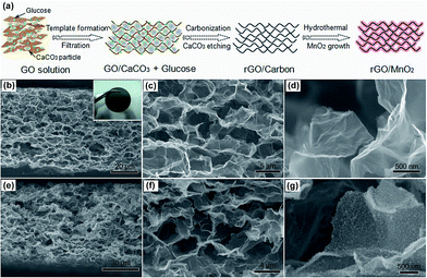
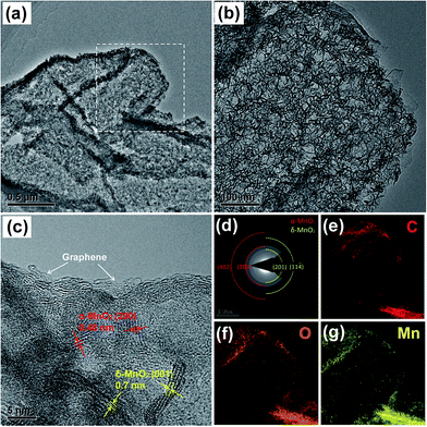
The 3D porous rGO/MnO2 thin-films were prepared by combining a modified template method38 and facile redox reaction between KMnO4 and amorphous carbon under hydrothermal condition. Fig. 1a illustrates a representative fabrication process of the hybrid film. More details can be found in the experiment section. Fig. 1b–g shows the typical scanning electron microscopy (SEM) images of the as-prepared rGO/C and rGO/MnO2 films. From the cross-section (Fig. 1b and c), it can be clearly seen that the free-standing rGO/C film (the inset of Fig. 1b) has a thickness of ∼60 μm and is composed of a continuous skeleton with irregular micrometer-sized pores. The pores interconnect with each other to form a 3D macroporous network. Also, the pore walls consist of a few layers of stacked graphene sheets which have quite smooth surface apart from some slight crumples, as shown in Fig. 1d. Fig. 1e–g shows the microstructure of the rGO/MnO2 film under different magnifications. It is obvious that the 3D porous architecture is well preserved without any aggregations among the pores after the hydrothermal reaction, suggesting that little damage was caused by the rapid and in situ redox reaction between KMnO4 and amorphous carbon. In the magnified Fig. 1g, we can see that the surface of the graphene sheets becomes remarkably rough but still seems to be semi-transparent, indicating the formation of ultrathin MnO2 nanostructures on the surface of graphene sheets. It should be noted that although there are some carbon defects in rGO, without the decoration of amorphous carbons, it is difficult to efficiently and uniformly form MnO2 ultrathin nanosheets on the surface of the rGO sheets, especially on the interior surface of the porous film (see ESI, Fig. S1†). It may be ascribed to the strong hydrophobic feature of the pure rGO film after thermal reduction, which severely prevents the intimate contact between KMnO4 solution and rGO sheets in short time. According to the nitrogen adsorption/desorption measurements (Fig. S2†), the rGO/MnO2 film exhibits a BET surface area of 203.0 m2 g−1 which is three times larger than that of the rGO/C film (62.6 m2 g−1). What's more, the hybrid film shows a dominated pore distribution below 20 nm, indicating that large amount of micro and macro-pores are introduced into the hybrid material after the redox reaction between carbon and KMnO4.The morphology and structure of the hybrid rGO/MnO2 thin-film were further investigated by transmission electron microscope (TEM). Fig. 2a and b demonstrate the typical TEM images of the composite in different magnifications. It is obvious that the as-synthesized MnO2 with nanosheet morphology is uniformly interconnected and coated on the surface of the graphene sheet, forming a conformal hybrid graphene/MnO2 nanostructure. The high-resolution TEM (HRTEM) image (Fig. 2c) reveals two different sets of lattice spacing, 0.7 nm and 0.48 nm, which can be assigned to the (001) plane of birnessite-type δ-MnO2 (JCPDS 42-1317) and the (200) plane of α-MnO2 (JCPDS 44-0141), respectively. This can be further verified by the selected area electron diffraction (SAED) patterns analysis, as shown in Fig. 2d. Both of them suggest that the resulting MnO2 nanosheets are the mixture of α- and δ-MnO2 which have been proved to be the best two candidates for supercapacitors among various MnO2 crystals.5,39,40 Moreover, from the HRTEM image, we can see that the standing nanosheet has a thickness of ∼3 nm, showing the ultrathin feature of the MnO2 nanostructures again. In addition, the energy-dispersive X-ray (EDX) mapping results of C, O and Mn (Fig. 2e and f) clearly verified the homogenous and conformal coating of MnO2 on the rGO micro-sheets. Element K is also detected on the EDX spectrum (Fig. S3†), which may come from surficial adsorption or inclination into the layer structures of δ-MnO2. This is consistent with our previous reports about the ultrathin δ-MnO2 nanosheets.40,46
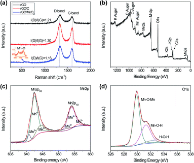
To investigate the graphitic structural properties of the pure rGO, rGO/C and rGO/MnO2 porous thin-films, Raman analysis were performed and shown in Fig. 3a. It is clear that all the spectra are dominated by the characteristic D and G band of rGO at around 1335 and 1596 cm−1, respectively.41 Besides, the rGO/MnO2 also shows two weak peaks at 565 and 644 cm−1 which can be attributed to the Mn–O lattice vibrations,42–44 confirming the yield of MnO2. Furthermore, the rGO/C film exhibits higher intensity ratio of D band and G band, i.e. I(D)/I(G), than the pure rGO film, indicating that lots of defects and imperfections are introduced into the rGO/C film with the modification of glucose carbonization.45 The increased defects in rGO/C thin-film could not only provide more active sites for the redox reaction between KMnO4 and carbon, but also greatly improve the hydrophilicity of the porous film which may be the key to uniformly synthesizing MnO2 nanosheets on the surfaces of rGO sheets. In addition, the rGO/MnO2 composite reveals some decrease of the I(D)/I(G) ratio compared with rGO/C. This may be caused by the active-carbon loss during the redox reaction under hydrothermal conditions.
To further detect the composition and surface chemical states of as-prepared hybrid rGO/MnO2 thin-film, X-ray photoelectron spectroscopy (XPS) analysis was performed and displayed in Fig. 3b–d. A typical XPS spectrum of the rGO/MnO2 is shown in Fig. 3b. Only four kinds of element (Mn, O, K and C) are detected, suggesting the purity of the sample. The precise region spectra for Mn2p and O1s are fitted and presented as well. In Fig. 3c, the Mn2p spectrum exhibits multiple splitting with two main peaks at 642.2 eV and 654.1 eV which can be assigned to Mn2p3/2 and Mn2p1/2 of Mn4+ in MnO2, respectively.9 Meanwhile, Mn3+ and Mn5+ peaks are also detected, but their intensity is much weaker than that for Mn4+, demonstrating the dominant role of Mn4+ in the composite.46 In the O1s region (Fig. 3d), three different peaks are deconvoluted at the binding energy of ∼529.9 eV, ∼531.3 eV and ∼532.3 eV, corresponding to various oxygen-containing chemical bonds: oxide (Mn–O–Mn), hydroxide (Mn–O–H) and water (H–O–H).47
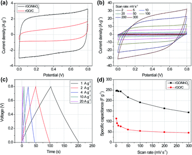
The electrochemical performances of the 3D porous rGO/MnO2 thin-film as supercapacitor electrode were evaluated in a symmetrical two-electrode system using glass fiber membrane as separator and 1.0 M Na2SO4 solution as electrolyte. Fig. 4a shows the cyclic voltammetry (CV) curves of the rGO/C and rGO/MnO2 thin-film electrode at the same scan rate of 20 mV s−1 with a potential window from 0 to 0.8 V. Both of them are near rectangular shape with symmetrical feature, implying the ideal electrical double-layer capacitive behaviour and a typical character of reversible redox reaction of the active materials.33 However, the rGO/MnO2 electrode exhibits much higher current density and integrated area than those for the rGO/C electrode, which highlights the significance of MnO2 ultrathin nanosheets in remarkably enhancing the overall capacitance of the composite film. Fig. 4b shows the CV curves of the rGO/MnO2 electrode at different scan rates from 2 to 300 mV s−1. It is obvious that the CV curve can still keep nearly rectangular and symmetrical shape at the high scan rate of 300 mV s−1, demonstrating the excellent electrochemical activity and high reversibility of the rGO/MnO2 film. The CV scanning results of the rGO/C films are shown in Fig. S4.† All of them exhibit the characteristic electrical double-layer capacitive (EDLC) shapes of carbon materials. It should be noted that no redox humps were detected on the CV curves for the rGO/MnO2 electrode. This phenomenon can be explained as follows. Briefly, in neutral aqueous Na2SO4 electrolyte, the charge/discharge mechanism of MnO2 mainly originates from two possible processes, i.e., an adsorption/desorption process of cations at the surface and/or an insertion/extraction process into the material bulk. It has been shown that the insertion/extraction process happens mostly on well crystallized bulk materials while the adsorption/desorption process occurs on weakly crystallized materials.48 In light of this report, no redox humps in our CV curves implies that the charge storage process in the present rGO/MnO2 hybrid electrode system is probably dominated by adsorption/desorption of cations at the MnO2 surfaces with rich crystalline defects and amorphous interspaces. This is highly agreeable with the structure feature of the MnO2 nanosheets as observed in the HRTEM image (Fig. 2c) and the blurry Debye–Scherrer diffraction rings in Fig. 2d.
Fig. 4c shows the galvanostatic charge/discharge (GCD) curves of the rGO/MnO2 electrode at different current densities ranging from 1 A g−1 to 20 A g−1. The charge and discharge pair curves are very symmetric and the slope of every part in each pair is nearly a constant, indirectly verifying the ideal capacitive behaviours of the rGO/MnO2 hybrid thin-film. Fig. 4d demonstrates the specific capacitances of the rGO/C and rGO/MnO2 thin-films at various scan rates. It can be clearly seen that the specific capacitance of the rGO/MnO2 electrode is about three times higher than that of the rGO/C, further confirming the crucial role of the MnO2 ultrathin nanosheets in the hybrid film. The specific capacitance of the rGO/MnO2 thin-film can reach 245 F g−1 at the scan rate of 2 mV s−1, which is better than some previous reports such as the 3D porous graphene/MnO2 nanorods (210 F g−1),49 3D graphene/MnO2 networks (130 F g−1)6 and 3D graphite/MnO2 nanoflakes (210 F g−1).36 Moreover, its specific capacitance keeps nearly constant below the scan rate of 20 mV s−1, and can still reach 145 F g−1 (∼58% of the maximum value) at a high scan rate of 300 mV s−1, which remarkably reflect the fast electron and ion transports in the 3D macroporous rGO/MnO2 hybrid thin-film.
To further detect the properties of charge and ion transfer in the rGO/C and rGO/MnO2 thin-film electrodes, electrochemical impedance spectroscopy (EIS) analysis was employed. Fig. 5a displays the typical Nyquist plots of these two samples. It is clear that in the high-frequency region the rGO/MnO2 electrode presents a bigger semicircle diameter than the rGO/C electrode. It implies that the rGO/MnO2 composite film has a little higher resistance from the electrochemical system and charge transfer than the rGO/C film, which can be attributed to the introduction of MnO2. However, in the low-frequency region, the rGO/MnO2 electrode shows a larger slope than the rGO/C, indicating that the nanostructured MnO2 on the rGO can reduce the diffusive resistance of electrolyte in the hybrid materials. Fig. 5b presents the cycle performances of the rGO/C and rGO/MnO2 thin-film electrodes at the current density of 2 A g−1. After 2000 cycles, 81% of the initial capacitance can be retained for the rGO/MnO2 electrode and 86% for the rGO/C electrode. The difference of capacitance retention may be attributed to the various categories of the electrode materials. It is well known that carbon materials have much more stable cycling performance than metal oxides because no chemical or compositional changes happen in their reversible non-faradic charge–discharge processes.46 In addition, it is noted that the rGO/C electrode shows an obvious gradually-increasing capacitance in the first 600 cycles. This may be caused by the gradual immersion or activation process of the micro- and meso-pores in the rGO/C thin-film, indirectly suggesting the poor ion diffusive behaviour in the system.
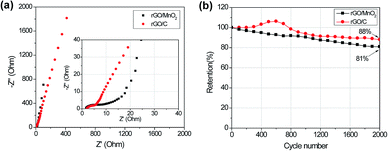 | ||
| Fig. 5 (a) EIS spectra of the rGO/C and rGO/MnO2 thin-films under the same condition; (b) capacitance retention of the two samples at the current density of 2 A g−1 during 2000 cycles. | ||
All the improved electrochemical performances of the 3D macroporous rGO/MnO2 thin-film mentioned above can be attributed to its unique hierarchical structures. Firstly, the ultra-thin MnO2 nanosheets are in situ anchored on the surfaces of rGO micro-sheets, greatly preventing the aggregation of MnO2, maximizing the utilization of the active materials and thus leading to a high specific capacitance for the whole thin-film. Moreover, the 3D macroporous and electrically conductive rGO structure provides the active MnO2 nanosheets with short ion diffusion paths and fast charge-transport routes to the current collector, which greatly favours the rate capability for high power performance.
Conclusion
In summary, a facile, low-cost and self-supporting 3D macroporous rGO/MnO2 nanosheets thin-film has been developed for supercapacitor thin-film electrode. The rGO/C porous thin-film was prepared via a simple glucose and CaCO3 particles mediated template method, and the MnO2 nanosheets were conformally synthesized on the rGO networks through the rapid redox reaction between amorphous carbon and KMnO4. The hierarchical rGO/MnO2 porous thin-film showed a high specific capacitance of 245 F g−1 at the scan rate of 2 mV s−1, and a good rate capability of 143 F g−1 at 300 mV s−1, and 81% of capacitance retention after 2000 cycles at 2 A g−1. These improved electrochemical performances endow the 3D porous rGO/MnO2-nanosheets hybrid thin-films with a potential value in the area of portable energy storage devices.Acknowledgements
The authors acknowledge the grants from National Basic Research Program of China (No. 2012CB933402). The authors also thank Kai Xu and Long Yang for their help in Raman analysis.Notes and references
- J. R. Miller and P. Simon, Science, 2008, 321, 651–652 CrossRef CAS PubMed.
- P. Simon and Y. Gogotsi, Nat. Mater., 2008, 7, 845–854 CrossRef CAS PubMed.
- X. Y. Lang, A. Hirata, T. Fujita and M. W. Chen, Nat. Nanotechnol., 2011, 6, 232–236 CrossRef CAS PubMed.
- H. Y. Lee and J. B. Goodenough, J. Solid State Chem., 1999, 144, 220–223 CrossRef CAS.
- W. F. Wei, X. W. Cui, W. X. Chen and D. G. Ivey, Chem. Soc. Rev., 2011, 40, 1697–1721 RSC.
- Y. He, W. Chen, X. Li, Z. Zhang, J. Fu, C. Zhao and E. Xie, ACS Nano, 2012, 7, 174–182 CrossRef PubMed.
- H. Jiang, C. Li, T. Sun and J. Ma, Nanoscale, 2012, 4, 807–812 RSC.
- S. Park, H.-W. Shim, C. W. Lee, H. J. Song, I. J. Park, J.-C. Kim, K. S. Hong and D.-W. Kim, Nano Res., 2014, 1–15 Search PubMed.
- M. Toupin, T. Brousse and D. Bélanger, Chem. Mater., 2004, 16, 3184–3190 CrossRef CAS.
- Z. F. Zeng, P. Sun, J. L. Zhu and X. H. Zhu, RSC Adv., 2015, 5, 17550–17558 RSC.
- P. Ahuja, S. K. Ujjain, R. K. Sharma and G. Singh, RSC Adv., 2014, 4, 57192–57199 RSC.
- Q. Li, Z.-L. Wang, G.-R. Li, R. Guo, L.-X. Ding and Y.-X. Tong, Nano Lett., 2012, 12, 3803–3807 CrossRef CAS PubMed.
- C.-L. Ho and M.-S. Wu, J. Phys. Chem. C, 2011, 115, 22068–22074 CAS.
- T.-T. Lee, J.-R. Hong, W.-C. Lin, C.-C. Hu, P.-W. Wu and Y.-Y. Li, J. Electrochem. Soc., 2014, 161, H598–H605 CrossRef CAS PubMed.
- Q. Li, X.-F. Lu, H. Xu, Y.-X. Tong and G.-R. Li, ACS Appl. Mater. Interfaces, 2014, 6, 2726–2733 CAS.
- Z. Fan, J. Yan, T. Wei, L. Zhi, G. Ning, T. Li and F. Wei, Adv. Funct. Mater., 2011, 21, 2366–2375 CrossRef CAS PubMed.
- D. Deng, B.-S. Kim, M. Gopiraman and I. S. Kim, RSC Adv., 2015, 5, 81492–81498 RSC.
- L. Bao, J. Zang and X. Li, Nano Lett., 2011, 11, 1215–1220 CrossRef CAS PubMed.
- X. Lu, T. Zhai, X. Zhang, Y. Shen, L. Yuan, B. Hu, L. Gong, J. Chen, Y. Gao and J. Zhou, Adv. Mater., 2012, 24, 938–944 CrossRef CAS PubMed.
- J. Yan, E. Khoo, A. Sumboja and P. S. Lee, ACS Nano, 2010, 4, 4247–4255 CrossRef CAS PubMed.
- G. Eda, G. Fanchini and M. Chhowalla, Nat. Nanotechnol., 2008, 3, 270–274 CrossRef CAS PubMed.
- C. H. Lui, L. Liu, K. F. Mak, G. W. Flynn and T. F. Heinz, Nature, 2009, 462, 339–341 CrossRef CAS PubMed.
- X. Cao, Y. Shi, W. Shi, G. Lu, X. Huang, Q. Yan, Q. Zhang and H. Zhang, Small, 2011, 7, 3163–3168 CrossRef CAS PubMed.
- J.-B. Sim, S. Mayavanab and S.-M. Choi, RSC Adv., 2015, 5, 42516–42525 RSC.
- Y. R. Kang, F. Cai, H. Y. Chen, M. H. Chen, R. Zhang and Q. W. Li, RSC Adv., 2015, 5, 6136–6141 RSC.
- S. Chen, J. Zhu, X. Wu, Q. Han and X. Wang, ACS Nano, 2010, 4, 2822–2830 CrossRef CAS PubMed.
- J. Zhu and J. He, ACS Appl. Mater. Interfaces, 2012, 4, 1770–1776 CAS.
- S. Yang, X. Song, P. Zhang and L. Gao, ACS Appl. Mater. Interfaces, 2013, 5, 3317–3322 CAS.
- J. Yan, Z. Fan, T. Wei, W. Qian, M. Zhang and F. Wei, Carbon, 2010, 48, 3825–3833 CrossRef CAS PubMed.
- M.-T. Lee, C.-Y. Fan, Y.-C. Wang, H.-Y. Li, J.-K. Chang and C.-M. Tseng, J. Mater. Chem. A, 2013, 1, 3395–3405 CAS.
- X. Feng, N. Chen, Y. Zhang, Z. Yan, X. Liu, Y. Ma, Q. Shen, L. Wang and W. Huang, J. Mater. Chem. A, 2014, 2, 9178–9184 CAS.
- D. R. Rolison, J. W. Long, J. C. Lytle, A. E. Fischer, C. P. Rhodes, T. M. McEvoy, M. E. Bourg and A. M. Lubers, Chem. Soc. Rev., 2009, 38, 226–252 RSC.
- B. G. Choi, M. Yang, W. H. Hong, J. W. Choi and Y. S. Huh, ACS Nano, 2012, 6, 4020–4028 CrossRef CAS PubMed.
- Y. M. Sun, Y. B. Cheng, K. He, A. J. Zhou and H. W. Duan, RSC Adv., 2015, 5, 10178–10186 RSC.
- Y. F. Zhang, M. Z. Ma, J. Yang, W. Huang and X. C. Dong, RSC Adv., 2014, 4, 8466–8471 RSC.
- X. Sun, H. Wang, Z. Lei, Z. Liu and L. Wei, RSC Adv., 2014, 4, 30233–30240 RSC.
- R. Offeman and W. Hummers, J. Am. Chem. Soc., 1958, 80, 1339 CrossRef.
- Y. Meng, K. Wang, Y. Zhang and Z. Wei, Adv. Mater., 2013, 25, 6985–6990 CrossRef CAS PubMed.
- V. Subramanian, H. W. Zhu, R. Vajtai, P. M. Ajayan and B. Q. Wei, J. Phys. Chem. B, 2005, 109, 20207–20214 CrossRef CAS PubMed.
- Y. Zhao, Y. Meng and P. Jiang, J. Power Sources, 2014, 259, 219–226 CrossRef CAS PubMed.
- A. Ferrari, J. Meyer, V. Scardaci, C. Casiraghi, M. Lazzeri, F. Mauri, S. Piscanec, D. Jiang, K. Novoselov and S. Roth, Phys. Rev. Lett., 2006, 97, 187401 CrossRef CAS.
- T. W. Kim, H. Yoo, I. Y. Kim, H. W. Ha, A. R. Han, J. S. Chang, J. S. Lee and S. J. Hwang, Adv. Funct. Mater., 2011, 21, 2301–2310 CrossRef CAS PubMed.
- M. Polverejan, J. C. Villegas and S. L. Suib, J. Am. Chem. Soc., 2004, 126, 7774–7775 CrossRef CAS PubMed.
- G. X. Zhao, J. X. Li, L. Jiang, H. L. Dong, X. K. Wang and W. P. Hu, Chem. Sci., 2012, 3, 433–437 RSC.
- S.-W. Lee, S.-M. Bak, C.-W. Lee, C. Jaye, D. A. Fischer, B.-K. Kim, X.-Q. Yang, K.-W. Nam and K.-B. Kim, J. Phys. Chem. C, 2014, 118, 2834–2843 CAS.
- Y. Zhao and P. Jiang, Colloids Surf., A, 2014, 444, 232–239 CrossRef CAS PubMed.
- M. Chigane and M. Ishikawa, J. Electrochem. Soc., 2000, 147, 2246–2251 CrossRef CAS PubMed.
- P. Ragupathy, H. N. Vasan and N. Munichandraiah, J. Electrochem. Soc., 2008, 155, A34–A40 CrossRef CAS PubMed.
- Y. Shao, H. Wang, Q. Zhang and Y. Li, J. Mater. Chem. C, 2013, 1, 1245–1251 RSC.
Footnote |
| † Electronic supplementary information (ESI) available: SEM image of rGO film after hydrothermal process, N2 adsorption/desorption isotherms, EDS analysis of rGO/MnO2, CV curves of rGO/C, and specific capacitance from charge/discharge curves. See DOI: 10.1039/c5ra18691a |
| This journal is © The Royal Society of Chemistry 2015 |


